Capturing Architecture Evolution with Maps of Architectural Decisions 2.0 Andrzej Zalewski, Szymon Kijas, and Dorota Sokołowska Warsaw University of Technology, Institute of Automatic Control and Computational Engineering
[email protected],
[email protected]
Abstract. Modern IT systems evolve being re-architected throughout their entire lifetime. Existing architecture decision-making approaches are oriented towards systems design, rather than systems evolution. However, real-life architecture evolution is substantially different to initial architectural design. It is a disorderly process, in most cases unrepeatable, and therefore difficult to be put into a predefined rut as most approaches try to do. MAD 2.0 model has been developed to support architect-practitioners working on systems evolution. It does not impose any predefined classification or hierarchy of architectural decisions and assumes a limited number of kinds of relations between architectural decisions. This makes a model of the decision process intuitive and easy to comprehend. To explain the choices made and capture their rationale, the entire decision situation is presented, including: the decision topic, considered design options, relevant requirements, and the advantages and disadvantages of every considered option. The proposed models and approach, supported by an appropriate modelling tool, has been validated in the real life conditions of one of the telecom companies. Keywords: architectural decisions, architectural knowledge, diagrammatic representation.
1 Introduction Recent developments in systems architectures, especially service-oriented architectures, concepts of business process management or enterprise service bus promote transition from design-oriented to evolution-oriented engineering. Evolution is an intensive process nowadays, dominating a system’s lifetime. We argue in section 2 that re-architecting substantially differs from initial design, and so it requires an approach to architecture decision-making tailored to its specificity. The purpose of this paper is to present an approach to support and capture architecture decision making during system evolution, which has been validated in practice. The notation MAD 2.0, used here as a model of architecture decisions and decision making process, is an extension of our former work [9]. MAD 2.0 was inspired by the outcomes of a workshop held with architects-practitioners – see section 2. I. Crnkovic, V. Gruhn, and M. Book (Eds.): ECSA 2011, LNCS 6903, pp. 83–96, 2011. © Springer-Verlag Berlin Heidelberg 2011
84
A. Zalewski, S. Kijas, and D. Sokołowska
The rest of the paper is organised as follows: the MAD 2.0 model and its components are presented in section 3, tool supporting the notation is characterised in section 4, the practical application of MAD 2.0 is shown in section 5, the results are widely discussed in section 6 against the background of existing architecture decisionmaking models and approaches, with a paper summary and further research prospects comprising section 7.
2 Inspiration The development of the MAD 2.0 notation and modelling approach was directly inspired by observations made during a workshop held with 22 IT architects working for one of the largest telecom firms in Poland. Architects focus mainly on the evolution of this entire complex system-of-systems, consisting of more than 100 systems integrated with a BPM solution based on SOA. The workshop was aimed at developing architects’ skills by teaching and practicing concepts from the area of architecture decision-making, e.g. architecture decision modelling, with text records [3], decisions classifications [4], [5], identifying and classifying relations between the architectural decisions as well as architecture decision-making approach presented in [4]. The survey performed at the end of the workshop showed that: • almost 80% of architects found the presented concepts and models as overcomplicated, • about 65% found them not adequate to their everyday jobs, • about 90% stated they always work under time pressure and have very little time to document architectural knowledge, • almost 75% assessed the repeatability of their work as low, and another 15% saw their work as unrepeatable, • almost 80% lack important architectural knowledge on existing systems. These results confirm the concerns as to whether architecture decision-making really helps to manage complexity, as presented in [10]. However, there are also deeper, fundamental reasons for such perception. Telecoms belong to the class of “emergent organisations”, whose systems are “subject to constant urgent change” (comp. [12]). Their evolution is rather a random than a highly predictable, carefully deliberated process following an earlier established path as in [13]. We analysed 25 cases of changes made to the systems. All of them were driven by an unexpected and unforeseeable change or emergence of business needs (e.g. changes to tariffs, development of new tariffs or new product support, esp. support for product bundles). In such conditions architects make architectural decisions rather disorderly, trying to achieve solutions based on reuse and adaptation of existing systems as well as purchase of new ones. Such decisions do not match any particular predefined abstraction levels or classifications like [4], [5]. They usually cannot be reapplied as a predefined solution to other problems. Existing architecture decision making models and methods are more oriented on well-structured architecture development than on its rapid, chaotic changes.
Capturing Architecture Evolution with Maps of Architectural Decisions 2.0
85
The survey and subsequent analysis of change cases indicated that to extend the architect’s everyday practice with architectural knowledge capturing and documenting [1]: • architectural knowledge has to be captured as it emerges – together with the resolution of architectural problems; • the overhang connected with capturing architectural knowledge has to be minimised; • decision-making concepts have to be easy to comprehend. This led us back to the idea of mind-mapping architectural decisions sketched in our earlier paper [9]. The Maps of Architectural Decisions notation was redesigned with consultation with architect-practitioners and tool supporting architecture decisionmaking was developed to validate the whole concept in practice.
3 MAD 2.0 Notation and Modelling Approach MAD 2.0 was crafted to assist architects in architecture decision-making, without enforcing any particular architecting approach or decision-making order. MAD 2.0 works similarly to popular mind maps used to graphically present a problem structure. The model consists of two diagrams Architecture Decision Relationship Diagrams (ADRD) – section 3.1, and Architecture Decision Problem Maps (ADPM) – section 3.2). ADRD represents the logic of the decision-making process – the diagram can be developed gradually, while ADPM models the internal structure of a single decision problem. The notation’s syntax and validity rules have been presented in section 3.3. 3.1 Architecture Decisions Relationship Diagram (ADRD) The Architecture Decisions Relationship Diagram is built out of just two basic elements (fig. 1): • Decision problem – represents the architectural issue being considered; Attributes: problem name, problem description, status, creation date, resolution date, extended solution rationale. States: defined – indicates a newly defined project, being solved – an ADPM for the problem has been created, but the problem has not been resolved yet, resolved, requires reassessment – indicates that solution, or the occurrence of other problem, requires reconsidering an already resolved problem. • Connector – in its basic form shows just that one problem led architect to the one indicated by an arrow, in the form with a hexagon it indicates that the solution of a given problem constrains the possible solutions of the pointed problem (“constrains relation”). Two Decision problems can be connected only once.
86
A. Zalewski, S. Kijas, and D. Sokołowska Symbols representing Decision Problems and their possible states:
Connector symbols:
Simple dependency
Constrains relationship
Fig. 1. The Elements of an Architectural Decisions Relationship Diagram
Problems can group on the ADRD by surrounding some of them with a solid line – compare fig. 5. Such a group is treated like a single problem. This way architects can indicate that problems concern a closely-related issue (e.g. define domain solution). 3.2 Architecture Decision Problem Map (ADPM) The Architecture Decision Problem Map is where architectural decisions are actually captured. The diagram was constructed to show the structure of a given architectural problem (issue) consisting of: Decision-maker, set of relevant Requirements, considered Solutions together with their Pros and Cons. If a given solution meets certain requirements, it is considered as a Pro, otherwise it is a Con. The latter is a key change made to the diagram in comparison with its version presented in [9]. The elements of the ADPM diagram have been summarised in fig. 2. The central element of a diagram is a single decision problem symbol (as in fig. 1) representing the architectural issue (problem) being analysed. The other symbols are: • Solution – represents a single solution to the architectural problem considered Attributes: name, state, description, generated problems. States: defined – assigned immediately after creating an element; feasible – indicates a solution meeting all the requirements, infeasible – indicates a solution that does not meet one of the requirements (the two former states are assigned automatically), chosen – indicates the finally selected solution (assigned by the decision-maker). • Requirements – represents a requirement relevant to a given architectural problem Attributes: name, description • Decision-maker – represents a person or a group of people responsible for the resolution of a related architectural problem. Attributes: name, remarks • Pro or Con – represents a single advantage or disadvantage of a given solution Attributes: name, description, state, related requirement (met or unmet requirement if the given element represents such a case)
Capturing Architecture Evolution with Maps of Architectural Decisions 2.0
87
State: defined – assigned immediately after creating a given Pro or Con element; minor, medium, major – declares the importance of a given advantage or disadvantage of a given solution. Symbols representing Solutions to the problem and their different statuses:
Symbols representing Cons of a given Solution:
Symbols representing Pros of a given Solution:
Decision maker:
Relevant requirement:
Fig. 2. The Elements of ADPM Diagram
3.3 Model Syntax and Validity Rules The syntax of the MAD 2.0 model is quite intuitive; here is a summary of the rules: • Rule 1. Two decisions represented on ADRD may be unconnected or connected with just a single connector. • Rule 2. Decision-maker, Requirement and Solution symbol on ADPM can only be attached to a Decision problem symbol. • Rule 3. Pros and Cons symbols on ADPM can only be attached to a solution symbol. Although, MAD 2.0 models are semiformal by nature, the syntax imposes a certain structure of the information representing architectural decisions enhancing the potential of model analysis. • Rule 1. Every decision problem has to be resolved, i.e. one of the solutions chosen. • Rule 2. Every solution has to be assessed in the context of every requirement relevant to the given problem. All these requirements have to be finally classified as either Pros (requirement met) or Cons (requirement not met) of a given solution.
88
A. Zalewski, S. Kijas, and D. Sokołowska
• Rule 3. Every Pro (Advantage) or Con (Disadvantage) may be attached to a given solution only once. • Rule 4. Only a single solution to a given problem can be in the “Chosen” state. • Rule 5. Pros and Cons connected with a given solution cannot be mutually contradictory. • Rule 6. Two solutions to a problem cannot designate virtually the same resolution to the same architectural problem. Rules 1-4 can be verified automatically, while rules 5-6 can be verified with a model walkthrough.
4 A Modelling Tool for MAD 2.0 We developed a software tool supporting MAD 2.0 to validate its concepts in practice. The tool is designed as a diagram editor being an extension to MS Word. Architects and analysts often create documentation with MS Word (despite the availability of more advanced specification and modelling tools). Therefore, to capture the knowledge as it emerges, it seems to be a good idea to bring the architecture decision modelling tool as close as possible to the general documentation tool. This makes it possible to connect decisions to the relevant fragments of system documentation.
Fig. 3. Example – creating a new decision problem
Capturing Architecture Evolution with Maps of Architectural Decisions 2.0
89
The tool provides a diagram editor for ADRD and ADPM, which can be invoked from the MS Word menu. It imposes model syntax and provides for model verification as described in section 3.3. Some screenshots are shown in fig. 3 and 4.
Fig. 4. Editing ADRD diagram
5 A Case Study MAD 2.0 was validated on a real world system evolution case study. This was done with the same telecom company we had a workshop with a couple of months earlier. This company offers various telecommunication services (called products). The dealers use a set of various specialised applications to serve their clients. These are mainly CRM applications supporting the selling process at all its stages: client registration or identification, product offer, product support and modification. The company wants to offer a new product composed of the installation and maintenance of fibre optic networks services and the delivery of IT equipment being sold together as a product bundle. The product can be sold by two subsidiaries of the telecom company under their own brand. There are various financing options planned for such a product: wire transfer, credit instalment payments or even leasing. The product components will be provided by two independent external subcontractors: “subcontractor A” will deliver IT equipment, “subcontractor B” will install fibre-optic networks in the clients’ premises and will configure the delivered equipment so that both elements operate together.
90
A. Zalewski, S. Kijas, and D. Sokołowska
The overall structure of the architecting task has been depicted in fig. 5 with ADRD, which comprises the following architectural decisions: 1. CRM system selection – product sales are supposed to be supported with a CRM system. However, as a result of a number of mergers/acquisitions there are a number of CRM systems used originally by the merged companies. None of them contains a complete client database; they support different product business models. 2. Selection of the billing system – There are two such systems, though each of them contains only a part of the entire client dataset. Moreover, these parts overlap substantially. 3. Selection of the help desk system – as such services have not been offered to clients yet, the help desk system used so far for internal purposes is one option, and the development of a newer system is another one. 4. Selection of subcontractor B – This is both a technical and business decision. 5. Selection of subcontractor A – This is both a technical and business decision 6. Which subsidiary will offer the product? – there are two subsidiaries of the telecom company that can offer the product under their own brands; however, they differ a lot in terms of their own IT systems and IT infrastructure, while it is necessary to interface appropriate systems of telecom company with those used by subsidiary or at least to enable subsidiary to access some systems of mother company. 7. Should lease and loan options be processed separately? – the accounting department uses different systems for these two options, while from the vendor’s point of view it is sensible to use a single system for both. 8. Where to store product offer model – The product list of the company should be accessible to other systems, so they have to support the same product business model. It is supposed to be synchronised with the product list of subcontractor A. 9. Scope of data needed for client verification – describes the set of data needed to assess a client’s financial credibility; 10. Selection of credit rating system – there are a number of systems (internal and external) that can be used to assess the client’s financial credibility; 11. Allocation of instalment calculator – the question is where to allocate the calculator’s functionality – should it be extending one of the applications used by product sellers, or should it be a separate system; 12. Communication mechanism between company and subcontractor A? – the communications necessary to keep the vendor’s data (product list, warehouse, client order processing support etc.) up to date; 13. Selection of product list exchange mechanism – the product lists of subcontractor A and the telecom company have to be periodically synchronised; 14. Frequency of product list exchange – to achieve this, various database synchronisation mechanisms may be needed. Fig. 5 shows that the resolution of problem No 6 leads to problems Nos 1, 2, 3; the resolution of issue No 8 leads to a group of problems concerning organising systems interaction necessary to support product delivery.
Capturing Architecture Evolution with Maps of Architectural Decisions 2.0
91
Fig. 5. ADPM developed for the case study
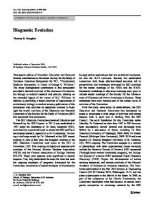
Fig. 6. ADPM for the problem of CRM selection
ADPMs were developed for all the architectural problems shown in fig. 5. We show only two out of fourteen diagrams modelling architectural problems and decision-making. Fig. 6 shows the structure of problem No 1 concerning the selection
92
A. Zalewski, S. Kijas, and D. Sokołowska
of an appropriate CRM system to support the new offer. The CRM system should be developable or customisable in a short time, it should support: all the customers (complete client database), frequent offer changes, provide client data and support full product list including the new product. Four existing or developed CRM systems are candidate solutions; the architect has to choose only one of them. In this case the solution is very easy to identify – only CRM 2 meets all the requirements. Obviously in many cases the situation will not be as clear cut as this time, and may require an individual judgement. Problem no. 3 concerning the selection of the helpdesk system has been presented in fig. 7. ADPM shows that there are three possible choices here. In this case as well, only one of the candidates meets the prescribed requirement of supporting the hardware help desk.
Fig. 7. ADPM for the problem of service desk support system selection
6 Discussion: Related Work Developing models supporting architectural decision-making, we face the classical dilemma between model usability (i.e. simplicity, legibility, comprehensibility, etc.) and its complexity defining its expressiveness (i.e. information capacity, level of formalisation) and analysability. The more complicated the model, the less usable it is, and vice versa: we can increase usability by decreasing model’s complexity, and by the same its expressiveness and the range of analyses it enables. Over-complicated
Capturing Architecture Evolution with Maps of Architectural Decisions 2.0
93
architecture decision-making models create complexity of their own, adding to the complexity of the overall systems construction instead of supporting complexity control [10]. In such a discussion we find semiformal diagrams a rational choice. Semiformal diagrammatic modelling has turned out to provide the right balance between model usability and complexity. For this reason, semiformal diagrams have been dominating software engineering for at least the past thirty years, in the form of structured and object-oriented methods. MAD 2.0 models have been crafted to assist system architects similarly to create mind maps. This helps to capture architectural knowledge as it gradually comes to light while elaborating the architecture (i.e. decision-making). The model is certainly not overloaded with information, though it is still possible to verify some consistency/completeness rules (section 3.3). In terms of the level of formalism, MAD 2.0 stands between text models e.g. [3], [11], and partially formalised models [4]. An extended comparison of these models contains table 1. Although, the range of information concerning architectural decisions and decision making process has been limited, the most important components of architectural knowledge are still preserved, i.e. decision’s rationale, considered solutions and their pros and cons. ADPM is similar to the rationale model of [8]. An assessment of every possible problem solution by indicating the pros and cons thereof seems intuitive and comes from the early works of Bosch [2]. It can also be found in the most modern developments like [7]. The classification of ADs and top-down decision-making as proposed in [4] is perfectly suited to developing a system from scratch. It more closely resembles the configuration of a predefined recurring solution rather than the resolution of a unique problem that requires creative thinking. It is difficult to apply categories defined in [4] or [5] to unstructured problems resulting from the evolution of systems of systems. If one considers the architectural problems listed in section 5, it will turn out that they are generally difficult to classify, with most of them belonging to the executive problem category. Architecting systems of systems mainly involves reusing existing systems, where the internal structure usually remains unchanged. Therefore, lower level architectural decisions (e.g. technology, vendor) play a less important role. MAD 2.0 assumes no predefined classification of architectural decisions, which is a reasonable decision in the above context. The other drawbacks of decision classification have been investigated in [10]. Only two kinds of relations between ADs are available in MAD 2.0. This provides for a smooth, uninterrupted flow of the architecting process, as architects do not need to worry about which of at least several kinds of relations to chose, which often becomes a separate challenge. This makes advanced analyses similar to that presented in [4] impossible, which is the price for higher model usability. The MAD 2.0 tool concept is similar to Knowledge Architect [6] – architectural decision models are linked to appropriate parts of requirement specifications. Although MAD 2.0 has been motivated by the rapid, random changes typical for the evolution of systems supporting emergent organisations it can also be used as a kind of light-weight architecture decision making model for the initial architecture development.
94
A. Zalewski, S. Kijas, and D. Sokołowska Table 1. Models supporting architectural decision making – a comparison Text models ([3], [11])
MAD 2.0
Graph/text model proposed in [4]
Model form
Text records
Diagrams, additional information stored in attributes of diagram elements
Graphs, certain elements accompanied with text attributes.
Level of formalism
Basic information structuring (fields of text records).
Syntax defined, simple consistency / completeness checking.
Syntax defined, extended completeness / consistency checking, decision-making consistency based on relations between ADs.
Information content
Issue, Decision, Status, Group, Assumptions, Constraints, Positions, Argument, Implications, Related decisions, Related requirements, Notes [3]
Decisions, two kinds of relations between ADs, problems (issues), possible solutions, pros and cons of every solution, chosen solution indicated, rationale.
Classification of architectural problems, possible solutions, pros and cons of every solution, chosen solution indicated, rationale.
Classification of ADs
No classification assumed, decisions can be put into groups according to the architects’ needs.
No classification assumed; decisions can be put into groups according to the architects’ needs.
Problems assigned to one of the levels: Executive, Conceptual, Technology, Vendor Asset. Each problem classified with topic groups mechanism.
Relations between ADs
Does not assume any particular types relations.
Only „lead to” and “constraints” relations.
Influences, refined by, decomposes into, forces, is incompatible with, is compatible with, triggers, has outcome.
Rationale modelling
Textual.
Diagrammatic, when necessary supported by additional textual explanations.
Textual.
Model analysis and verification
Manual walkthroughs only.
Limited to syntax enforcement, consistency / completeness with automated or manual walkthroughs.
Automatic verification of decision-making consistency, completeness and consistency checking.
Capturing Architecture Evolution with Maps of Architectural Decisions 2.0
95
7 Summary: Future Work The presented architecture decisions model MAD 2.0 has been tailored to the specific conditions of the evolution of systems of systems subject to constant urgent change typical. In such conditions, evolution turns out to be a highly creative, disordered process, performed under time pressure. MAD 2.0 can assist architecting activities, which helps capture architectural knowledge when it is created. It eliminates, or at least minimises, the need to document architectural decisions ex post. It also provides for basic automated verification as well as for model walkthroughs. MAD 2.0, together with modelling, has been validated in the real life conditions of a large enterprise on the same group of architects. Their perception has changed considerably: they were satisfied with such an evolution-oriented approach – the survey indicated that about 85% found it easy to learn and use. About 70% found it useful for their job. Future work will include: • Further empirical evaluation; • Analysing a larger number of evolution cases to develop a deeper insight in the architectural problems concerning the evolution of systems of systems; • Developing a classification of architectural problems connected with systems evolution; • Extending the information content of MAD 2.0 to widen the range of possible analyses; • Providing a view mechanism for managing large sets of MAD 2.0 models, where users define a subset of model components that should be presented to them extending the concepts from [14] onto MAD 2.0; • Integration of MAD 2.0 with other models of systems architecture, e.g. UML, BPMN. Acknowledgement. This work was sponsored by the Polish Ministry of Science and Higher Education under grant number 5321/B/T02/2010/39.
References 1. Ali Babar, M., et al.: Architecture knowledge management. In: Theory and Practice. Springer, Heidelberg (2009) 2. Bosch, J., Jansen, A.: Software Architecture as a Set of Architectural Design Decisions. In: 5thWorking IEEE/IFIP Conference on Software Architecture (WICSA 2005), pp. 109– 120. IEEE Computer Society, Los Alamitos (2005) 3. Tyree, J., Akerman, A.: Architecture Decisions: Demystifying Architecture. IEEE Software 22(2), 19–27 (2005) 4. Zimmermann, O., et al.: Managing architectural decision models with dependency relations, integrity constraints, and production rules. Journal of Systems and Software 82(8), 1249–1267 (2009) 5. Kruchten, P.: An Ontology of Architectural Design Decisions. In: 2nd Groningen Workshop on Software Variability Management, pp. 54–61. Rijksuniversiteit Groningen (October 2004)
96
A. Zalewski, S. Kijas, and D. Sokołowska
6. Jansen, A., Avgeriou, P., van der Ven, J.: Enriching Software Architecture Documentation. Journal of Systems and Software 82(8), 1232–1248 (2009) 7. Zimmermann, O.: Architectural Decisions as Reusable Design Assets. IEEE Software 28(1), 64–69 (2011) 8. Mojtaba Shahin, M., Liang, P., Reza Khayyambashi, M.: Improving understandability of architecture design through visualization of architectural design decision. In: SHARK 2010 Proceedings of the 2010 ICSE Workshop on Sharing and Reusing Architectural Knowledge. ACM, New York (2010) 9. Zalewski, A., Ludzia, M.: Diagrammatic Modeling of Architectural Decisions. In: Morrison, R., Balasubramaniam, D., Falkner, K. (eds.) ECSA 2008. LNCS, vol. 5292, pp. 350–353. Springer, Heidelberg (2008) 10. Zalewski, A., Kijas, S.: Architecture Decision-Making in Support of Complexity Control. In: Babar, M.A., Gorton, I. (eds.) ECSA 2010. LNCS, vol. 6285, pp. 501–504. Springer, Heidelberg (2010) 11. Harrison, N.B., Avgeriou, P., Zdun, U.: Using Patterns to Capture Architectural Decisions. IEEE Software 24(4), 38–45 (2007) 12. Bennett, K.H., Rajlich, V.T.: Software maintenance and evolution: a roadmap. In: Proceedings of the Conference on The Future of Software Engineering (ICSE 2000), pp. 73–87. ACM, New York (2000) 13. Garlan, D., Barnes, J.M., Schmerl, B., Celiku, O.: Evolution styles: Foundations and tool support for software architecture evolution. In: Joint Working IEEE/IFIP Conference on Software Architecture, 2009 & European Conference on Software Architecture, WICSA/ECSA 2009 September 14–17, pp.131–140 (2009) 14. Chen, L., Babar, M.A., Liang, H.: Model-Centered Customizable Architectural Design Decisions Management. In: 2010 21st Australian Software Engineering Conference (ASWEC), April 6-9, pp. 23–32 (2010)