A complete carrier frequency offset estimation and com- pensation scheme based ... as RFO compensation schemes were investigated in [4, 6, 7]. Specifically for LTE, a ..... this work has been co-funded by the Christian Doppler Lab- oratory for ...
The 21st Annual IEEE International Symposium on Personal, Indoor and Mobile Radio Communications (PIMRC'10)
Carrier Frequency Synchronization in the Downlink of 3GPP LTE Qi Wang, Christian Mehlf¨uhrer, and Markus Rupp Institute of Communications and Radio-Frequency Engineering Vienna University of Technology Gusshausstrasse 25/389, A-1040 Vienna, Austria Email: {qwang,chmehl,mrupp}@nt.tuwien.ac.at Web: http://www.nt.tuwien.ac.at/rapid-prototyping
Abstract—In this paper, we investigate carrier frequency synchronization in the downlink of 3GPP Long Term Evolution (LTE). A complete carrier frequency offset estimation and compensation scheme based on standardized synchronization signals and reference symbols is presented. The estimation performance in terms of mean square error is derived analytically and compared to simulation results. The impact of estimation error on the system performance is shown in terms of uncoded bit error ratio and physical layer coded throughput. Compared to perfect synchronization, the presented maximum likelihood estimator shows hardly any performance loss, even when the most sophisticated MIMO schemes of LTE are employed.
I. I NTRODUCTION Long Term Evolution (LTE) [1] has been standardized as the successor of the Universal Mobile Telecommunication System (UMTS). The downlink transmission utilizes Orthogonal Frequency Division Multiple Access (OFDMA) as the physical layer technique which enables high data rate transmission in frequency selective fading scenarios. However, one of the drawbacks of OFDMA is its vulnerability to Carrier Frequency Offset (CFO). Given a carrier frequency of 2.5 GHz, a typical frequency drift of 10ppm (10 × 10−6 ) of the local oscillator results in an offset of 25 kHz. In LTE, which employs a fixed subcarrier spacing of 15 kHz, such an offset corresponds to 1.67 subcarrier spacings. Synchronization for general OFDM systems has been investigated for example in [2–8]. The basic idea in these publications is to split the CFO into a Fractional Frequency Offset (FFO), an Integer Frequency Offset (IFO), and a Residual Frequency Offset (RFO), which can be estimated individually. In [2–4], a Cyclic Prefix (CP) based FFO estimator has been presented and the Cramer-Rao lower bound of this estimator has been derived in [8]. In order to expand the estimation range, an IFO estimator based on the maximum likelihood principle has been derived in [5]. The impact of RFO as well as RFO compensation schemes were investigated in [4, 6, 7]. Specifically for LTE, a synchronization concept was presented in [9]. However, the performance was only evaluated in terms of simulated Mean Squared Error (MSE). In this work, we present an entire chain of carrier frequency offset estimation blocks based on the standardized synchronization signals and reference symbols of LTE. Furthermore,
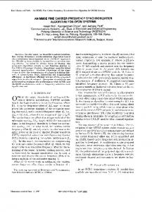
we derive analytic expressions for the MSE of the RFO and the FFO estimators. The mathematical analysis is complemented by simulations that are carried out using a standard compliant MATLAB-based downlink physical layer simulator for LTE [10]. In addition to the frequency offset MSE, also the system performance after compensation is evaluated in terms of uncoded bit error ratio and physical layer coded throughput. All algorithm implementations will be made publicly available in a future release of our LTE physical layer simulator [10]. The paper is organized as follows. In Section II, the standardized synchronization and reference signals of LTE are described. Section III explains our system model and the impact of CFO on an OFDM system. Our carrier frequency offset estimation scheme and its analytical MSE are presented in Section IV. Section V shows the physical layer simulation results. Finally we draw our conclusions in Section VI. II. S YNCHRONIZATION AND R EFERENCE S IGNALS IN LTE As specified in [11], radio frames in an LTE downlink transmission have a duration of Tframe = 10 ms. Each frame consists of 10 subframes of equal length. Each subframe contains two consecutive slots of time duration Tslot = 0.5 ms. The smallest scheduling unit is called one resource block which is a time-frequency grid of 12 subcarriers over Ns = 7 OFDM symbols for the normal CP length and Ns = 6 for the extended CP length. In the LTE downlink two kinds of signals can be utilized for synchronization at the receiver. Firstly, the dedicated synchronization signals, and secondly the cell-specific reference symbols. Both are briefly explained below. A. Synchronization Signals The LTE standard defines two synchronization signals, namely the primary (PSCH) and the secondary (SSCH). In FDD mode, these signals are located on the 62 subcarriers symmetrically arranged around the DC-carrier in the first slot in the sixth and seventh OFDM symbols of the first and the sixth subframes, as shown in Fig. 1. B. Cell-specific Reference Symbols Cell-specific reference signals utilize 4-QAM modulated symbol alphabets and are mapped to the resource elements
The 21st Annual IEEE International Symposium on Personal, Indoor and Mobile Radio Communications (PIMRC'10)
4
5
6
7
8
9
10
12 3 4 5 6 7 1 2 3 4 5 6 7
frequency
3
frequency
2
antenna port 2
SSCH
1 subframe 1ms 1
antenna port 1
PSCH
1 frame 10ms
time antenna port 3
1 2 3 4 5 6 7 1 2 3 4 5 6 7
reference symbol of antenna port 1 time antenna port 4
reference symbol of antenna port 2 reference symbol of antenna port 3
Synchronization signals in LTE FDD downlink.
III. C ARRIER F REQUENCY O FFSET IN OFDM In this section, we define an OFDM system model and show what impact a carrier frequency offset has on the OFDM signal. The transmitted time-domain OFDM signal is denoted (m) (m) by xl,n , the channel impulse response by hl,n , the additive (m) Gaussian noise by vl,n , and the received time-domain signal (m) by rl,n . Here, l is the OFDM symbol index within one subframe, n ∈ [1, N + Ng ] the time index within one OFDM symbol and m the receive antenna index. N denotes the FFT size and Ng the CP length. Using the above definitions, the transmission with CFO is described in the time-domain as n o (m) (m) (m) (m) rl,n = xl,n ∗ hl,n + vl,n · ej2πεCFO (n+l(N +Ng ))/N , (1) where εCFO is the frequency mismatch between transmitter and receiver carrier frequency normalized to the subcarrier spacing. (m) Correspondingly, we define in the frequency-domain Xl,k (m) as the transmitted symbol, Hl,k as the channel frequency (m) (m) response, Vl,k as the additive Gaussian noise, and Rl,k as the received symbol on the k-th subcarrier of the l-th OFDM symbol at the m-th receive antenna. When the discrete Fourier (m) transform is applied to the received signal rl,n in Eq. (1), we obtain according to [2] (m) (m) (m) (m) (m) Rl,k = γ · Xl,k0 Hl,k0 + Il,k0 + V˜l,k ,
(2)
with γ=
0 sin(πε0 ) · ejπε (N −1)/N · ej2πεCFO l(N +Ng )/N , 0 N sin(πε /N )
(3) (m)
Il,k0 =
sin(π(p + εCFO − k)) (m) (m) Xl,p Hl,p · N sin(π(p + εCFO − k)/N ) 0
X p6=k
· ejπ(p+εCFO −k)(N −1)/N · ej2πεCFO l(N +Ng )/N . (4)
Fig. 2.
“zero“ symbol time
time
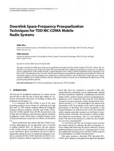
in the frequency domain as shown in Fig. 2. Whenever there is one antenna port transmitting a reference symbol on one resource element, all the other antenna ports transmit a ”zero” symbol at this position. Thus, interference of the reference symbols transmitted from different antennas is avoided and channel estimation is simplified.
reference symbol of antenna port 4
frequency
Fig. 1.
slot 1
frequency
slot 1
Cell-specific reference signals in LTE FDD downlink.
where the relations k 0 = k − εIFO and ε0 = εCFO − εIFO = εFFO + εRFO are used. The last relation is obtained because the total CFO can be split into the FFO, IFO, and the RFO: εCFO = εFFO + εIFO + εRFO . The factor γ is the degradation on (m) the desired subcarrier caused by the CFO. Il,k0 contains the inter-carrier interference from the neighboring subcarriers. The index k 0 implies that data symbols transmitted on subcarrier k − εIFO are received on subcarrier k. IV. C ARRIER F REQUENCY O FFSET E STIMATION S CHEME In this section, we develop a three-stage CFO compensation scheme for UMTS LTE. We assume the channel to be slow fading, that is, the variation of the channel impulse response within one subframe of duration 1 ms is negligible. A. FFO Estimation As shown in Eq. (3) and (4), FFO is the major source of inter-carrier interference destroying the orthogonality between subcarriers. Therefore, it has to be compensated before the FFT operation in the OFDM receiver. In [3], a Maximum Likelihood (ML) estimator for the FFO has been derived. In the context of slow fading, this method can be extended to subframe base as below: Ng Nf X NR X X ∗ 1 (m) (m) arg rl,n rl,n+N . (5) εˆFFO = − 2π m=1 l=1 n=1
In this equation, NR denotes the number of receive antennas, Nf the number of OFDM symbols in one subframe, and Ng the CP length. The estimation range (normalized to the subcarrier spacing) of this stage is (−0.5, 0.5) and is determined by the arg{·} operation. In an AWGN channel where sufficiently large SNR is assumed, the MSE of this FFO estimator can be derived as 2σv2 σr2 + σv4 2γt + 1 = ≈ 8π 2 NR Ng Nf σr4 8π 2 NR Ng Nf γt2 1 ≈ , 2 4π NR Ng Nf γt
MSEεFFO =
(6)
The 21st Annual IEEE International Symposium on Personal, Indoor and Mobile Radio Communications (PIMRC'10)
where γt = σr2 /σv2 � 1 is the signal-to-noise ratio of the received signal in time domain. A detailed derivation of Eq. (6) is provided in Appendix I. It is obvious that the estimation error can be reduced by using more receive antennas, by extending the CP length, or by taking more OFDM symbols into account. B. IFO Estimation After the FFO estimation stage, we assume the fractional part of the CFO has been mostly corrected. It can be seen from Eq. (2) and Eq. (3) that the integer part of the CFO has two effects on the received signal. The first is the FFT index shift, that is, the symbol transmitted on subcarrier k − εIFO is received on subcarrier k. The second effect is a phase rotation proportional to the OFDM index l. These two effects can be compensated once the IFO is estimated, for example by the ML estimator proposed in [5]. The symbols used for estimation can be either pre-defined pilots or PSK modulated data symbols. In the context of LTE, we choose to only apply it to the standardized synchronization signals, leading to the following IFO estimator: ( � j2πiNg (7) εˆIFO = arg max < e N · i
·
NR X
X �
(m)∗ (m) RSSCH,k+i RPSCH,k+i
) �∗ � �� (m)∗ (m) XSSCH,k XPSCH,k ,
m=1 k∈KSCH
where