Carving linearly JPEG images using Unique Hex Patterns(UHP)
Nurul Azma Abdullah1 , Rosziati Ibrahim1, Kamaruddin Malik Mohamad1 , Norhamreeza Abdul Hamid1 1
Faculty of Computer Science and Information Technology Universiti Tun Hussein Onn Malaysia, Johor, Malaysia {azma,rosziati,malik}@uthm.edu.my,
[email protected]
Abstract. Many studies have been conducted in addressing problem of fragmented JPEG. However, there are many scenarios in fragmentation yet to be solved. This paper is discussing of using pattern matching to identify single linear fragmented JPEG images. The main contribution of this paper is introducing Unique Hex Patterns (UHP) to carve single linear fragmented JPEG images. Keywords: JPEG image, pattern matching, file carving, DFRWS 2006/07
1 Introduction A method to recover files from the disk collected from the crime scene which is known as cyber evidences is called file carving [1, 2, 3]. Year by year, with the increasing number of computers and other digital devices usages, file carving technique also evolve drastically. In carving a JPEG images, the focus is in fragmentation file carving. It is an important issue in file carving since handling fragmentation can significantly improve the number of potential images successfully obtained from the crime scene. Statistic presented in [3] shows the fact that fragmentation in today’s file system is relatively infrequent. However, the capability of carving fragmented files which is not extensively explored is important for computer forensic because the possibility of files that interest forensic investigation to be fragmented is relatively high [3]. This paper discusses a technique in handling fragmentation especially fragmentation occurs in among JPEG files. In order to enhance the functionality of file carver is handling fragmentation efficiently. A file can be fragmented with another whether same types, different types or random data. Fragmentation can occur either linearly or nonlinear. According to [4], linear fragmentation occurs when a file has been fragmented and split into multiple parts with all parts are present in the dataset in their original order while nonlinear fragmentation is when the parts not in their original order or in reverse order. Joachim Metz, Bas Kloet and Robert-Jan Mora have developed Revit07 to handle linearly fragmented files including JPEG. However, they handle thumbnails same as handling original. This may result
thumbnail is assumed as a fragmentation point which may lead to falsely detect fragmentation point. In this paper, with consideration of thumbnail, we proposed new Unique Hex Patterns (UHP) to carve JPEG files including linearly fragmented JPEG files. The datasets used are from DFRWS 2006 and DFRWS2007 (DFRWS).
2 Related Works 2.1. An Overview of JPEG Standard Computer forensics is to recover evidences resides on a computer, by mean to solve pornography cases [1], [7], [8]. This involves image files obtained from the perpetrator in certain format like Bitmap and JPEG but most common format is JPEG. JPEG is popular because of its compressed file that can reduce the size required to allocate an image. Joint Photographic Experts Group (JPEG) was formed by International Telegraph and Telephone Consultative Committee in 1986 inspired by an effort of International Organization of Standard (ISO) to find ways to use high resolution graphics and pictures in computers [2]. JPEG introduced compression standard for both grayscale and color continuous-tone images. The details of JPEG compressed data formats can be found in [9]. There are two types of JPEG that are mostly used today, JPEG File Interchange Format (JFIF) and JPEG Exchangeable Image File Format (Exif) [10]. JFIF is popular for internet file while EXIF is the popular image file format used for digital camera [13]. JFIF (JPEG File Interchange Format) was introduced by Eric Hamilton in 1991. It is a minimal file format that allows JPEG bitstreams to be exchanged in multiplatform environment and wide variety range of applications. According to work done by [9], the APPO marker is included into JFIF structure as an additional requirement while maintaining the compatibility of JFIF with the standard JPEG format interchange. A JPEG file that apply JFIF standard contains a head signature that starts with SOI followed by hexadecimal string 0xFF E0 XX XX 4A 46 49 46 00 and ends with EOI [12]. In 1996 Exif (Exchangeable image file format) is introduced by JEITA standard who aimed to provide standard image format for digital cameras and other related equipments. JPEG Exif standard was created to stipulates the method of recording image data in files which specifies the structure of image data files, tags used by this standard and definition and management of format versions. Exif can be recognized by SOI and “Exif\0” identifier.
2.2. Fragmentation Point Less than 10% fragmentation occurred in a typical disk. However, Garfinkel [3] also found that most of fragmented files are potentially useful for forensics investigation. There are limitations of carving tools available today. Many concentrate on carving contiguous data file and do not provide with validator which resulting with many false positive files [3].
Identify applicable sponsor/s here. (sponsors)
A fragmented file is a condition where a file is split into two or multiple parts which can be in different locations in a dataset [4]. Pal, Sencar & Memon [11] explained that fragmented files are when a file is stored in non contiguous clusters. This will result in recovering process using traditional file carving technique will be failed and when using earlier automate file carving tool, incorrect files will be carved. A signature in header and footer has been used to carve in straightforward carving. This is a simple technique and has been proved successfully carve a contiguous files with an assumption that files clusters remain in order [5]. However, if files are fragmented, files can be disconnected and becomes unordered which cause the straightforward carving fail. In order to solve the fragmentation, detecting fragmentation point is required before carving those files. However, if files are fragmented, files can be disconnected and becomes unordered which cause the straightforward carving fail. Mohamad et al. in [6] pointed out the importance of focusing on fragmentation problem especially within DHT (Define Huffman Table) area because any damaged in DHT can cause image distortion or worse, corruption. Therefore DFRWS initiate efforts to encourage research within fragmented files carving by preparing data set contains some contiguous files while others were fragmented. Fragmentation point exists only when a file is fragmented into more than two parts. There are three approaches that have been discussed in [11] which are syntactical tests, statistical tests and basic sequential validation. Syntactical tests are when the fragmentation point is detected by validating the belonging of a block to a file through one of following methods: Using keywords and signatures to identify different file types Content analysis to identify incorrect block. Using this method, it can be confirmed that the validated block does not belong to any certain file. However, it is not certain that the previous block belongs or not belongs to the file. For statistical tests, the statistic of each block is compared to a model of each file type to identify the block. Cohen [2] used the mapping function to map between the bytes contained in the file to the bytes within the image itself. In this case, carving process is the process to estimate the mapping function. Statistical tests also facing problem in detecting the actual fragmentation point and even worse, using this technique, blocks can be falsely identified as belonging to another file type. The third technique is basic sequential validation. This technique is used to identify fragmentation point by validating block sequentially from the header through the blocks until the validator stops with an error. Using this technique, a last correctly validated block is marked to be the fragmentation point. However, this technique can result in incorrect recovery of a file because it can successfully validate random blocks of data. Alternative technique to identify fragmentation is by using cluster information. In a computer file system, a cluster or in DOS 4.0 known as an allocation unit or in UNIX System as block, is the smallest logical set that is created to perform actual erasure for files and directories [16], [17]. A cluster may contain the whole file or portion of files but a cluster only stores data for one file [18], [19]. Therefore, it is
important to determine the cluster’s size to determine the start of file. This information is useful for both steganography and file carving. In file carving, the whole content of the hard disk used for evidence need to be imaged (will be referred to as image file) in preparation for forensics investigation. The image file contains thousands of hex code representing all files in the hard disk used for evidence. It is impossible to read line by line manually in order to extract all files into their original form. Information about the start of file can be used to identify each file that resides in any dataset. PredClus as proposed in [15] is developed to automatically display the predicted cluster size according to probabilistic percentage. It concentrates on JPEG images. The information can be used to distinguish original with thumbnail/embedded JPEG files which can help to determine the real fragmentation point. A thumbnail can be easily mistaken for another JPEG file fragmented with the original. Once thumbnail is recognized, the carver can easily know which point is the real fragmentation occurs. However, this technique has limitation. For some rare cases where thumbnail is pushed to the start of cluster, it can be falsely identified as an original JPEG image. Hence, PattrecCarv is introduced where thumbnails and embedded JPEG files are carved using Unique Hex Patterns (UHP) as described in [20]. It carves more thumbnails compare to PredCLus.
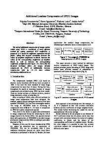
3 Frag_Carv Model This section discusses on the experiment designed for Frag_Carv model (as illustrated in Figure 1) is adapted from myKarve [14]. Two algorithms, PattrecCarv [20] and Pattern_temp are installed into the model. PattrecCarv accepts data sources from either image from physical memory, removable storage, hard disk or any JPEG file. However, for this particular experiment, we use dataset from DFRWS 2006 and 2007. This algorithm also searches for JPEG files location and store in ADB (Address Database). The other algorithm, Pattern_temp matches the header and footer with predefined patterns for original, thumbnails and embedded JPEG files. PattrecCarv is developed using C++ language while UHP_template is implemented in Matlab environment to simplify the pattern matching process.
DFRWS 2006 & DFRWS 2007
Unique Hex Pattern (UHP)
ADB
Header & Footer PattrecCarv
UHP_Template
Report Figure 1. Frag_Carv model
The following are some of the assumptions for this experiment: Baseline JPEG is being used for the experiment because of its popularity and simple file structure. Only JFIF and Exif format can be accepted by this model. JPEG 2000 is not compatible with this model. All the file headers and footers are in sequential order and not corrupted.
3.1. PattrecCarv PattrecCarv is inserted in Frag_Carv to identify thumbnails and embedded JPEG files. The algorithm of PattrecCarv[25] is introduced (illustrated in Figure. 2) to read raw data from DFRWS 2006 and 2007 dataset and mark thumbnails and embedded JPEG files with a different marker from original marker. 1. 2. 3. 4. 5. 6. 7. 8. 9. 10. 11. 12. 13. 14. 15. 16. 17. 18. 19.
Read data image Initialize hex_values Initialize thumb_markers Initialize embedded_markers Find JPEG header If found Jump to 9th hex_values If hex_values== embedded_markers Read CurrentOffset Save the CurrentOffset Else Read next hex_values If hex_values==thumb_markers Go to the most recent SOI Save the CurrentOffset (location of SOI) Endif Endif If not end of data image, repeat step 5 Generate report
Figure 2. Algorithm used in PattrecCarv for carving thumbnails and embedded JPEG files
First, data from dataset is read. These data are in hex values. The hex values then matched with the standard JPEG header. However, in this experiment, additional markers are also used instead of standard JPEG headers and footers, 0xFFD8 alone. The additional markers which are 0xFFE0, 0xFFE1, 0xFFE2, 0xFFC4 and 0xFFDB and standard headers/footers are known as validated markers. The validated headers are used to reduce false detection of JPEG files. When matched, the offset for each markers matched is retrieved. Using UHP as described in [Abdullah], all thumbnails and embedded JPEG files are identified and standard headers for the files are renamed with a special name to indicate the type, either thumbnail (TN_FFD8) or embedded JPEG file (EF_FFD8). This is to differentiate them from original header (FFD8). After all thumbnails and embedded files are determined, all locations for JPEG standard headers/footers are then stored in ADB (Address database). The markers and locations will be the input to Pattern_temp.
3.2. UHP_Template UHP_Template is a database contains UHP for different scenarios of JPEG as shown in Figure 4 and Figure 5. First, it reads ADB for headers and matches the header with predefined patterns. So, from the output, we can view different patterns of JPEG files, either JPEG file without thumbnail, JPEG file with one thumbnail or JPEG file with two thumbnails. If we found a pattern where two headers (original JPEG file) found consecutively, this indicate fragmentation scenario. Below is the algorithm for Pattern_temp (as illustrated in Figure.3) which is according to patterns template shown in Figure 4 and Figure 5.
1. 2.
Read ADB If match ‘pattern 1’ a. Write to pattern 1 column in output file. Endif .
3. . . . 4. 5. 6. 7.
Else if match ‘pattern n’ a. Write to pattern n column in output file Endif If not end of data image, repeat step 1 Exit
Figure. 3. Algorithm used in Pattern_temp.
Figure 4. Pattern 1-7 for different scenarios of JPEG files
Figure 5. Pattern 8-13 for different scenarios of JPEG files
4 Experimentation Generally, there are three major steps involved in Frag_Carv model to complete this experiment namely pre-processing, pattern matching and JPEG image file carving. During the pre-processing, a dataset is read and searched for JPEG headers and footers. The real concern is to automatically determine the correct header-footer pairing to match the predefined pattern. In this model, a header-footer is paired if the validated header-footer is strictly matched one of the introduced UHP. This is to validate the read data are belongs to a JPEG file. Only then, with the addition of special markers to reduce false detection, these headers and footer along with their locations are populated in ADB. Next, the ADB is ready for pattern matching process. During pattern matching process, all headers and footers are read from ADB. These headers and footers then matched with the predefined patterns namely pattern 1, pattern 2, and pattern 3 until pattern 13. Pattern 1 is a pattern for JPEG image without thumbnail, pattern 2, for JPEG image with one thumbnail, Pattern 3, for JPEG image with two thumbnails, Pattern 4 is for two JPEG images without thumbnail intertwined with each other, Pattern 5 and 7 for intertwined JPEG images where one JPEG image has one thumbnail, while Pattern 6 and 8 are same as Pattern 5 and 7 but this time, the file contains two thumbnails. The same goes with Pattern 9-12, they are differ with each other depending on which file contain one or two thumbnails. Finally, the last step in this model is carving JPEG images according to patterns described above. Once, a pattern is determined, the headers and footers are stored in an output file along with their locations. For this experiment, the output file is in Excel format to simplify the analysis process later. All patterns are organized in different columns so that it is easy to view and read.
5 Result and Discussion Although there are 13 patterns discussed above, by implementing datasets from DFRWS 2006 and 2007, only few patterns are carved. The screenshot of the output can be clearly examined in Figure 6, Figure 7 and Figure 8. When we differentiate thumbnail’s header from the standard JPEG header, we can easily confident that Pattern 2 is capturing fragmented JPEG images, where a non complete JPEG image is followed by another JPEG image. This scenario will cause distortion when viewed in image viewer. Now, the investigator can concentrate on these fragmented image instead wasting time investigate a complete image that is mistaken to be fragmented JPEG images. Furthermore, in Figure 6, we can see clearly the different of carving a contiguous images and fragmented images. For Pattern 1, the output shows that there is a consecutive order of headers and footers found. This indicates a complete JPEG image can be carved using this pattern. In other hand, for Pattern 2, there is a second header found before the footer. This indicates, there is a fragmentation occurs at that point. From the output, we can easily assume that there is a complete JPEG image in the middle of another JPEG image. Hence, we can carve these files as two separate images.
Figure 6. Example of output for pattern 1 and 2.
Figure 7. Example of output for pattern 5 and pattern 6
Figure 8. Example of output for pattern 5 and pattern 6
6 Conclusion A JPEG image can contains none, single or two thumbnails in the image itself. A thumbnail which is a reduced version of an image carried similar feature as the original. This thumbnail is always mistaken as another JPEG image. Therefore, knowledge of thumbnail’s existence helps investigator to separate JPEG files with thumbnail/s and concentrates to investigate correct point where the real fragmentation occurs. They can then identify which JPEG image is fragmented with another JPEG images. With this way, they can ascertain that those fragments are belongs to another JPEG file, not file/s (thumbnail) within a JPEG file. This is important because during the reassembling process, if a thumbnail is mistakenly identified as another JPEG files, the original file may corrupt because of missing fragments and also wasting investigator’s time in looking for fragmentation while the fragmentation does not exist. Subsequently, this is also accelerating the reassembling process by allowing investigators to concentrate on real fragmentation situation. In conclusion, by recognizing thumbnail, false fragmentation detection can be reduced significantly.
7 Future Work There is a limitation of this technique in carving fragmented JPEG images. From the experiment, we found that, Pattern 2 is also valid for a scenario where two JPEG files intertwined with each other where each file is split into two parts and not in contiguous location. Using only pattern matching will result distorted images carved. Further investigation using different technique is required to solve this scenario. Nevertheless, using pattern matching technique, we can save time for investigating fragmentation point which require more times because we have to check upon the files by its contents. By applying this technique, we can separate the complete carved image from the images with distortion where it can be further investigated.
Acknowledgement
The authors would like to thank Ministry of Science, Technology and Innovation (MOSTI), for granting Science Fund (Vote s019) to support this research.
References 1. 2. 3. 4. 5. 6. 7. 8. 9.
10. 11. 12. 13. 14. 15.
16. 17. 18. 19. 20.
S. L. Garfinkel, “Digital Forensic Research :The next 10 years,” Digital Investigation, vol. 7(1), 2010, pp. S64-S73. M. I. Cohen, “Advanced Carving Techniques,” Digital Investigation, vol. 4(1-4), 2007, pp. 119128. S. L. Garfinkel, “Carving Contiguous and Fragmented Files with Fast Object Validation,” Digital Investigation, vol. 4(1), 2007, pp. S2-S12. S. J. J. Kloet, Measuring and Improving the Quality of File Carving Methods, Master Thesis, Endhoven University of Technology, 2007. C. J. Veenman, Statistical Disk Cluster Classification for FIle Carving. Proc. of the Third International Symposium on Information Assurance and Security, Machester, 2007. K. M. Mohamad, M. Mat Deris, Fragmentation Point Detection of JPEG Images at DHT Using Validator. Proc. of the 2009 FGIT, 2009, pp.173-180. A., Pal, & N. Memon, “Automated reassembly of the file fragmented images using greedy algorithms,” IEEE Trans. Image Processing, vol. 15(2), pp. 385-393, 2003. M. Karresand, & N. Shahmehri, Reassembly of fragmented jpeg images containing restart markers. in 2008 European conference on computer network defense, 2008. The International Telegraph and Telephone Consultative Committee (CCITT). Information technology—digital compression and coding of continuous-tone still images–requirements and guideline (ITU-T T.81), 1992. Retrieved Sept. 5, 2012, from World Wide Web Consortium (W3C): http://www.w3.org/Graphics/JPEG/itu-t81.pdf S. Bettelli, “ The structure of JPEG pictures,” 2006. Retrieved Sept. 5, 2012 from : http://search.cpan.org/dist/Image-MetaData-JPEG/lib/Image/MetaData/JPEG/Structures.pod Pal, J. T. Sencar, & N. Memon, “Detecting File Fragmentation Point Using Sequential Hypothesis Testing,” Digital Investigation,vol. 5, 2008, pp. S2-S13 2008. K. M. Mohamad, & M. Mat Deris, Visualization of JPEG metadata. in: Proceeding of the 2009 first International Visual Informatics Conference on Visual Informatics,2009. P. Alvarez, “Using extended file information (exif) file headers in digital evidence analysis,” International Journal of Digital Evidence. Vol. 2(3), 2004. K.M. Mohamad, A. Patel, T. Herawan, & M. Mat Deris, “myKarve: JPEG image and thumbnail carver,” Journal of Digital Forensic Practice, vol. 3, 2011, pp. 74-97. N. A. Abdullah, R. Ibrahim, & K. M. Mohamad, Cluster size determination using JPEG files. in Proceedings of the 12th international conference on Computational Science and Its Applications, 2012. S. W. Ng, “Advances in Disk Technology: Performance Issues,” Computer, vol. 31,1998, pp. 75-81. File Allocation Table, http://en.wikipedia.org/wiki/File_Allocation_Table#Boot_Sector R. P. Jemigan & S. D. Quinn, Two-Pass Defragmentation of Compressed Hard Disk Data with a Single Data Rewrite. U.S Patent 5574907 . Cluster Size for NTFS, FAT, and ExFAT, http://support.microsoft.com/kb/140365 N. A. Abdullah, R. Ibrahim & K. M. Mohamad, “ Carving Thumbnail/s and Embedded JPEG Files Using Image Pattern Matching, “ JSEA, vol. 6, 2013, pp. 62-66.