The dark shaded portion of the chart illustrates the region where cavitation
damage may occur. The lighter shaded portion is where significant cavitation
noise ...
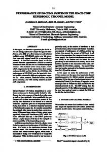
CAVITATION GUIDE
The chart is based on cavitation index (sigma) values as defined by Utah State University Water Research Laboratory. =
(P2 — Pv) (P1 — P2)
where
Cavitation Zones 100-01/100-20 300
Inlet Pressure (psi)
The dark shaded portion of the chart illustrates the region where cavitation damage may occur. The lighter shaded portion is where significant cavitation noise and vibration may occur. Operating conditions inside the dark shaded area is permissible for infrequent periods of short duration. The guide is for modulating service valves. For on/off valves, consult factory.
= cavitation index, P1 = inlet pressure (psi), P2 = outlet pressure (psi),
Cavitation Noise Zone
280 260
Cavitation Damage Zone
240 220 200 180 160
Pv = water vapor pressure (psig).
140
The dark shaded portion is below of 0.5 and the lighter shaded area is below of 0.8. The chart is to be used for typical valve operating conditions below 40% open at standard water temperature and elevation below 1000 feet.
120
This chart should be used as a general guide for determining safe operating pressure drop conditions for Cla-Val modulating service control valves.
100 80 60
More accurate cavitation conditions are determined from the Cla-CAV analysis program including static and dynamic inlet and outlet pressures, flow range, elevation, water temperature, and service conditions. If operation is inside the shaded areas, the Cla-CAV analysis can be used to determine whether added backpressure from an orifice plate, a second valve in series, or adding KO Anti-Cavitation trim (see 100-01KO data sheet). is necessary.
40 20 0 0
10
20
30
40
50
60
70
80
90
100 110
120 130
Outlet Pressure (psi)
For a more detailed cavitation analysis or if operation will be outside of the above chart, request a Cla-CAV computer analysis. Cla-CAV can evaluate what options best solve any potential cavitation problem. In the example shown, a 6 inch 100-01 modulating service valve requires an orifice plate downstream to prevent damaging cavitation. For wider flow range service, either an extra valve in series or the addition of KO Anti-Cavitation trim to the valve may be necessary (see 100-01KO data sheet). Consult factory for a free analysis for wide open or modulating service valves.
Cavitiation Characteristics 1.4 1.3 1.2 1.1 1.0 0.9 0.8 0.7 0.6 0.5 0.4 0.3 0.2 0.1 0.0 0
200
400
600
800
1000
Flow (gpm) Valve 1
Orifice 1
If the lines go above 1.0 there will be cavitiation damage.
CLA-VAL
P.O. Box 1325 • Newport Beach, CA 92659-0325 • Phone: 949-722-4800 • Fax: 949-548-5441 • E-mail:
[email protected] • Website cla-val.com
© Copyright
Cla-Val 2011 Printed in USA Specifications subject to change without notice.
E-Cavitation Guide (R-3/2011)