APPLIED PHYSICS LETTERS 96, 233112 共2010兲
Surround-gated vertical nanowire quantum dots M. H. M. van Weert,1 M. den Heijer,1 M. P. van Kouwen,1 R. E. Algra,2,a兲 E. P. A. M. Bakkers,1,b兲 L. P. Kouwenhoven,1 and V. Zwiller1,c兲 1
Kavli Institute of Nanoscience, Delft University of Technology, Delft, Zuid Holland 2628CJ, The Netherlands 2 Philips Research Eindhoven, Eindhoven, Noord Brabant 5600AE, The Netherlands
共Received 5 May 2010; accepted 14 May 2010; published online 11 June 2010兲 We report voltage dependent photoluminescence experiments on single indium arsenide phosphide 共InAsP兲 quantum dots embedded in vertical surround-gated indium phosphide 共InP兲 nanowires. We show that by tuning the gate voltage, we can access different quantum dot charge states. We study the anisotropic exchange splitting by polarization analysis, and identify the neutral and singly charged exciton. These results are important for spin addressability in a charge tunable nanowire quantum dot. © 2010 American Institute of Physics. 关doi:10.1063/1.3452346兴 Optically active quantum dots are sources for single1 and entangled2 photons and allow for single electron charging.3 These properties make them highly interesting for quantum information processing.4 Recently, initialization,5,6 manipulation,7,8 and readout of single spins have been demonstrated experimentally in such systems. Semiconducting nanowires possess an unprecedented material and design freedom,9 and offer the possibility of combining optically active quantum dots10,11 with electrostatically defined quantum dots,12 which would allow for the combination of local electron spin manipulation in the electrostatically defined dot and fast optical readout via the optically active quantum dot. Nanowire quantum dots have excellent optical quality,13 and allow for electron charging down to the single electron level.14 The proposed schemes for initializing and manipulating a single electron spin in a charged exciton 共trion兲, using self-assembled quantum dots, require polarization selective excitation of spin states.15,16 In nanowires, this can be achieved by directing the light along the nanowire axis.17 Thus, access to intrinsic polarization of a charge tunable nanowire quantum dot requires electrical contacts on a vertically aligned nanowire quantum dot. Here, we demonstrate single electron charging and optical readout of the polarization state by fabricating capacitively coupled surround-gates18 around as-grown nanowire quantum dots. The neutral exciton state is identified by polarization analysis of the gate voltage dependent emission lines. This charge state identification by polarization, combined with the ability to selectively excite specific spin states in the dots,13 shows that spin initialization and manipulation of a singly charged exciton, using the excitation polarization, is feasible in nanowire quantum dots. The InAsP quantum dots, embedded in InP nanowires, are grown in the vapor-liquid-solid mode using metalorganic vapor-phase epitaxy.19 Growth details can be found in Ref. 13. The distance between the nanowires is larger than the spatial resolution of our optical setup 共⬃1 m兲, enabling single dot excitation. Active areas are defined by op-
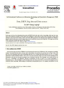
tical lithography and subsequent etching of nanowires outside active areas. This substrate patterning is performed postgrowth, in order to avoid effects on the quantum dot growth. A scanning electron microscope 共SEM兲 image of an active area containing four nanowires is shown in Fig. 1共a兲. As gate dielectric, 200 nm silicon oxide 共SiO2兲 is deposited using plasma-enhanced chemical vapor deposition. This method allows for deposition temperatures of 300 ° C, preventing out-diffusion of arsenic and phosphorus. As gate metal, 15 nm titanium nitride 共TiN兲 is sputtered onto the sample. A SEM image of a nanowire embedded in these two layers is shown in Fig. 1共b兲. For this figure, a 100 nm TiN layer is used to visualize the layer in SEM. A photoresist layer with a thickness exceeding the nanowire length is spun. This resist layer is etched back to the quantum dot height using an oxygen plasma. This process is depicted schematically in Fig. 1共c兲. The TiN layer is etched subsequently from the part of the nanowires that stick out of the resist using a CF4 plasma. The TiN is then patterned by photolithography. Figure 1共d兲 shows a SEM image of a nanowire embedded in SiO2, and an opened 共100 nm兲 TiN surround gate. Electrical connections are made to the gate and the wafer back side, to which a voltage difference, Vgate, can be applied.
Also at Materials Innovation Institute 共M2I兲, Delft, The Netherlands, and IMM, Solid State Chemistry, Radboud University Nijmegen, The Netherlands. b兲 Also at Eindhoven University of Technology, Eindhoven, The Netherlands. c兲 Electronic mail:
[email protected].
FIG. 1. 共Color online兲 共a兲 Schematic of as-grown nanowire quantum dots. The SEM image shows an active area containing four nanowires. 共b兲 Schematic and SEM image showing a nanowire covered with gate dielectric 共SiO2兲 and gate metal 共TiN兲. 共c兲 Schematics of the etch-back process defining the gate height. 共d兲 Schematic and SEM image of the device.
a兲
0003-6951/2010/96共23兲/233112/3/$30.00
(a)
(b)
InP
TiN
(c)
(d)
SiO2
QD
InP define active area
InP deposit oxide and metal
InP define gate height
InP surroundgated QD
500nm 2μm
96, 233112-1
500nm
© 2010 American Institute of Physics
Downloaded 01 Jul 2010 to 131.180.39.25. Redistribution subject to AIP license or copyright; see http://apl.aip.org/apl/copyright.jsp
(b) 1-
1.34 0
1.33
PL (cts/s)
600 400
X 100
X
0
X
1-
200 −5 0 5 Gate voltage (V)
(c)
40 V=-5.4V 20
X1-
X
0
X0
|↑⇓+↓⇑>
(a)
EF(V)
80 V=2.85V X140 0
X1X
0
FIG. 2. 共Color online兲 共a兲 Top panel shows color plot of gate voltage dependent PL spectra. Bottom panel shows integrated PL intensity of the X0 共maximum at −5 V兲 and X1− 共maximum at 2.5 V兲 as function of gate voltage. 共b兲 PL spectrum at Vgate = −5.4 V 共top panel兲 and Vgate = 2.85 V 共bottom panel兲. The positions of the two line cuts shown in 共b兲 are indicated in the top panel of 共a兲 by the two vertical dashed lines. 共c兲 Schematic representations of the dot energy levels. By tuning the electrochemical potential EF, the ground state contains either zero or one electron, resulting in X0 共upper schematic兲 or X1− 共lower schematic兲, respectively.
Microphotoluminescence 共PL兲 studies were performed at 4.2 K. The nanowire quantum dot devices were excited with a linearly polarized tunable titanium sapphire continuous wave laser focused to a spot size of ⬃1 m using a microscope objective with a numerical aperture NA = 0.65. The PL signal was collected by the same objective and was sent to a spectrometer, which dispersed the PL onto a nitrogen-cooled silicon array detector with 30 eV resolution. Linear and circular emission polarizations were analyzed using a half- or quarter-waveplate, respectively, followed by a fixed polarizer. Voltages were applied using battery driven voltage sources. Currents down to 10 fA could be measured. To avoid screening of the voltage by photoexcited charges in the InP nanowire and substrate, we used quasiresonant excitation in the p-shell 共Eexc = 1.36 eV兲.13 The top panel of Fig. 2共a兲 shows the surround-gate voltage dependent PL spectra of the quantum dot s-shell. Figure 2共b兲 shows two spectra, taken at Vgate = −5.4 V 共top panel兲 and 2.85 V 共bottom panel兲. For gate voltages of ⫾6 V or larger, a measurable leakage current 共⬃20 pA兲 was found. At large negative gate voltages, one dominant emission line is found at 1.349 eV, assigned to the neutral exciton X0. The intensity of this emission line decreases by tuning the gate voltage to positive values. Simultaneously, the emission line at 1.345 eV, assigned to X1− 共we will motivate the assignments by polarization studies later兲, increases in intensity. This is seen more quantitatively in the bottom panel of Fig. 2共a兲, where the integrated intensities of both lines are plotted as function of gate voltage. The total added intensity of the two lines is not constant, since a third emission line appears at 1.34 eV. Also the overlap of the two emission lines is large: the two lines are visible across the whole voltage range investigated. This indicates that tunnel rates are small compared to the radiative rate. This is to be expected, since from the electric field generated, only a small component points along the nanowire axis. Hence, tunnel couplings are not changed by the surround-gate. Instead of tilting the bands, the gate induces a change in electrochemical potential EF, as depicted schematically in Fig. 2共c兲. The difference in emission energy of 3 meV between X0 and X1− is due to Coulomb interaction, and corresponds very well to what is observed in similar dots,14 and to what is calculated for dots of such size.20
(b)
|↑↓,⇓> (|↑↓,⇑>)
σ- (σ+)
H
|0>
EF(V)
1.33 1.35 Energy (eV)
Δ |↑⇓−↓⇑>
V
0
X0
4 H PL intensity (cts/s)
X
1.35
0
PL intensity (cts/s)
Energy (eV)
(a)
Int. intensity (cts/s)
Appl. Phys. Lett. 96, 233112 共2010兲
van Weert et al.
0 4
|↓> (|↑>) 4 H
X1-
0 V
2 V 0
0 2 H-V
Δ=43μeV
2 H-V
Δ=8μeV
0
0 1.347 1.348 1.349 Energy (eV) (c) Number of measurements
233112-2
−2
1.344 1.345 1.346 Energy (eV)
(d) 30
0
X
30
20
20
10
10
0
−50 0 50 EH - EV (μeV)
0
X1-
−50 0 50 EH - EV (μeV)
FIG. 3. 共Color online兲 共a兲 Horizontal 共top panel兲 and vertical 共middle panel兲 polarization analysis of the neutral exciton X0. Lower panel shows horizontal minus vertical polarization. Thick solid lines are fits of the data 共thin solid lines兲. 共b兲 Similar polarization analysis as in 共a兲 but now for the singly charged exciton X1−. 关共c兲–共d兲兴 Histograms of the energy differences between fits of the horizontal and vertical polarizations for 共c兲 X0 and 共d兲 X1−.
The assignment of the 1.349 eV emission line to neutral exciton emission X0 is substantiated by polarization analysis. A full Stokes analysis is performed on the PL as a function of gate voltage. Figures 3共a兲 and 3共b兲 show the horizontal and vertical polarization analysis of the emission line at E = 1.349 eV 共1.345 eV兲 in the top panel and the middle panel, respectively. The lower panel shows the difference of the two polarizations 共horizontal minus vertical兲. The thick solid curves are fits to the data, used to determine the exact emission energy. In Fig. 3共a兲 a significant difference in emission energy for the two polarizations is observed 共⌬ = 43 eV兲, indicating a splitting due to the anisotropic exchange interaction.21 This interaction originates from exchange between the electron and hole spin 关see energy level diagram in Fig. 3共a兲兴. Observation of such an anisotropic exchange splitting is a strong indication of neutral exciton emission.22 By tuning to a more positive voltage, the emission line at 1.345 eV dominates the spectrum. This line does not show an anisotropic exchange splitting, as can be seen from Fig. 3共b兲. For X1− no anisotropic exchange splitting is expected: the two electrons in the dot form a singlet with zero spin, resulting in vanishing exchange terms 关see energy level diagram in Fig. 3共b兲兴. Since the double and triple charged excitons all exhibit an exchange splitting,20 it can be concluded that the two dominant emission lines observed in the device originate from X0 and X1− emission. The biexciton, however, could
Downloaded 01 Jul 2010 to 131.180.39.25. Redistribution subject to AIP license or copyright; see http://apl.aip.org/apl/copyright.jsp
233112-3
not be identified by polarization analysis; the emission line at 1.34 eV did not show an anisotropic exchange splitting, possibly due to the low intensity of less than one count per second; spectral diffusion might smear out the two polarization states. An extensive polarization analysis on X0 and X1− is shown as a histogram in Fig. 3共c兲 for X0 and Fig. 3共d兲 for X1−. These statistics show that the exchange splitting in X0 is ⌬ = 40⫾ 10 eV and 0 ⫾ 15 eV for X1−. The large spread in these numbers is due to the low intensity of the peaks and the relatively large spectral diffusion: linewidths are about 200 eV. The magnitude of the X0 splitting is comparable to what is usually found in self-assembled dots but rather unexpected, since nanowire quantum dots are believed to be highly symmetric.23 Nonuniform strain, induced by the surrounding oxide could result in an enhanced anisotropic exchange interaction. No effect of the gate voltage on the magnitude of the anisotropic exchange splitting of X0 has been observed. In conclusion, we have fabricated quantum dots in vertically aligned, surround-gated nanowires, crucial for accessing the polarization properties of the dots. These devices show single electron charging. The neutral X0 and singly charged X1− excitons are identified by polarization analysis. These results demonstrate that quantum dots in vertical nanowire devices are promising for single electron spin manipulation by means of electron spin to polarization coupling. We acknowledge W. van den Einden, A. Helman, and G. Immink for help and fruitful discussions. This work was supported by the European FP6 NODE 共Grant No. 015783兲 project, the Dutch Organization for Fundamental Research on Matter 共FOM兲, The Netherlands Organization for Scientific Research 共NWO兲, and the Dutch ministry of economic affairs 共NanoNed兲. The work of R.E.A. was carried out under Project No. MC3.0524 in the framework of the strategic research program of the Materials Innovation Institute 共M2I兲 共www.m2i.nl兲. 1
Appl. Phys. Lett. 96, 233112 共2010兲
van Weert et al.
P. Michler, A. Kiraz, C. Becher, W. V. Schoenfeld, P. M. Petroff, L. Zhang, E. Hu, and A. Imamoglu, Science 290, 2282 共2000兲.
2
N. Akopian, N. H. Lindner, E. Poem, Y. Berlatzky, J. Avron, D. Gershoni, B. D. Gerardot, and P. M. Petroff, Phys. Rev. Lett. 96, 130501 共2006兲. 3 A. Hartmann, Y. Ducommun, E. Kapon, U. Hohenester, and E. Molinari, Phys. Rev. Lett. 84, 5648 共2000兲. 4 N. Gisin and R. Thew, Nat. Photonics 1, 165 共2007兲. 5 M. Atatüre, J. Dreiser, A. Badolato, A. Högele, K. Karrai, and A. Imamoglu, Science 312, 551 共2006兲. 6 B. D. Gerardot, D. Brunner, P. A. Dalgarno, P. Öhberg, S. Seidl, M. Kroner, K. Karrai, N. G. Stoltz, P. M. Petroff, and R. J. Warburton, Nature 共London兲 451, 441 共2008兲. 7 J. Berezovsky, M. H. Mikkelsen, N. G. Stoltz, L. A. Coldren, and D. D. Awschalom, Science, 320, 349 共2008兲. 8 D. Press, T. D. Ladd, B. Zhang, and Y. Yamamoto, Nature 共London兲 456, 218 共2008兲. 9 C. M. Lieber and Z. L. Wang, MRS Bull. 32, 99 共2007兲. 10 M. T. Borgström, V. Zwiller, E. Muller, and A. Imamoglu, Nano Lett. 5, 1439 共2005兲. 11 E. D. Minot, F. Kelkensberg, M. van Kouwen, J. A. van Dam, L. P. Kouwenhoven, V. Zwiller, M. T. Borgström, O. Wunnicke, M. A. Verheijen, and E. P. A. M. Bakkers, Nano Lett. 7, 367 共2007兲. 12 C. Fasth, A. Fuhrer, M. T. Björk, and L. Samuelson, Nano Lett. 5, 1487 共2005兲. 13 M. H. M. van Weert, N. Akopian, U. Perinetti, M. P. van Kouwen, R. E. Algra, M. A. Verheijen, E. P. Bakkers, L. P. Kouwenhoven, and V. Zwiller, Nano Lett. 9, 1989 共2009兲. 14 M. P. van Kouwen, M. E. Reimer, A. W. Hidma, M. H. M. van Weert, R. E. Algra, E. P. A. M. Bakkers, L. P. Kouwenhoven, and V. Zwiller, Nano Lett. 10, 1817 共2010兲. 15 A. Shabaev, A. L. Efros, D. Gammon, and I. A. Merkulov, Phys. Rev. B 68, 201305 共2003兲. 16 O. Gywat, H.-A. Engel, D. Loss, R. J. Epstein, F. M. Mendoza, and D. D. Awschalom, Phys. Rev. B 69, 205303 共2004兲. 17 M. H. M. van Weert, N. Akopian, F. Kelkensberg, U. Perinetti, M. P. van Kouwen, J. Gómez Rivas, M. T. Borgström, R. E. Algra, M. A. Verheijen, E. P. A. M. Bakkers, L. P. Kouwenhoven, and V. Zwiller, Small 5, 2134 共2009兲. 18 H. T. Ng, J. Han, T. Yamada, P. Nguyen, Y. P. Chen, and M. Meyyappan, Nano Lett. 4, 1247 共2004兲. 19 K. Hiruma, T. Katsuyama, K. Ogawa, M. Koguchi, H. Kakibayashi, and G. P. Morgan, Appl. Phys. Lett. 59, 431 共1991兲. 20 M. Ediger, G. Bester, A. Badolato, P. M. Petroff, K. Karrai, A. Zunger, and R. J. Warburton, Nat. Phys. 3, 774 共2007兲. 21 M. Bayer, G. Ortner, O. Stern, A. Kuther, A. A. Gorbunov, A. Forchel, P. Hawrylak, S. Fafard, K. Hinzer, T. L. Reinecke, S. N. Walck, J. P. Reithmaier, F. Klopf, and F. Schäfer, Phys. Rev. B 65, 195315 共2002兲. 22 E. Poem, J. Shemesh, I. Marderfeld, D. Galushko, N. Akopian, D. Gershoni, B. D. Gerardot, A. Badolato, and P. M. Petroff, Phys. Rev. B 76, 235304 共2007兲. 23 R. Singh and G. Bester, Phys. Rev. Lett. 103, 063601 共2009兲.
Downloaded 01 Jul 2010 to 131.180.39.25. Redistribution subject to AIP license or copyright; see http://apl.aip.org/apl/copyright.jsp