5LPM-01
1
Certification of Superconducting SolenoidBased Focusing Lenses E. Joseph DiMarco, Ali M. Hemmati, Darryl F. Orris, Thomas M. Page, Roger H. Rabehl, Michael A. Tartaglia, Iouri Terechkine, John C. Tompkins
Abstract— The first production focusing lens for the HINS beam line at Fermilab has been assembled into a cryostat and tested. A total of 5 devices will be tested before they are installed in the low energy section of the HINS beam line, which uses copper Crossbar-H (CH) style RF cavities. One of the tested CHsection lens assemblies includes a pair of weak orthogonal steering dipoles nested within a strong focusing solenoid, and has six vapor cooled power leads. The other device has only the strong focusing solenoid, and utilizes a single pair of HTS power leads. The production test program is designed to measure the thermal performance of the cryostat, minimum cooling requirements for the HTS leads, quench performance of all superconducting components, and precise determination of the magnetic axis and field angles. Results and future plans for the first production device tests are presented. Index Terms— Accelerator Magnet
Superconducting,
Solenoid,
Cryostat,
I. INTRODUCTION
A
N R&D linac at Fermilab has been under development for several years [1]. The front end beam line design has a compact lattice that requires superconducting solenoid lenses to focus the proton beam. The beam line is comprised of three separate accelerating sections, which are identified by the type of RF structures used and the range of energies over which they apply. The CH-section operates from 2.5 to 10 MeV using room temperature Crossbar-H style copper RF cavities, while the SS1(10-30 MeV) and SS2 (30-60 MeV) sections will use superconducting spoke resonator RF cavities. As the beam energy grows, integrated strength of the solenoids must also increase: therefore three separate solenoid designs are needed for the three accelerating sections of the linac. To allow for alignment offsets in the beam line, some steering elements are needed; thus, each section includes some “Type1” solenoids (without steering dipoles) and “Type-2” solenoids with embedded horizontal and vertical steering dipole coils. The design and performance of solenoids for the SS1 and SS2 sections is presented in a separate report [2].
Manuscript received 3 August 2010. This manuscript has been authored by Fermi Research Alliance, LLC under Contract No. DE-AC02-07CH11359 with the U.S. Department of Energy. All authors are with the Fermi National Accelerator Laboratory, Batavia, IL 60510 USA (corresponding author phone: 630-840-3890; fax: 630-8408079; e-mail:
[email protected]).
This paper relates to the CH-section solenoids, which require the use of a cryostat to provide the necessary cooling conditions for the superconducting lens. A total of 23 solenoids were fabricated and tested by an industrial vendor, whereupon a subset were re-tested at Fermilab as a quality assurance measure, to confirm that performance requirements were met. A summary of results from 20 production solenoids tested in their helium vessels has been previously reported [3]. These production solenoids are now being assembled into cryostats and tested, before installation of the lenses in the HINS beam line to conduct studies of solenoid focusing. II. CRYOSTAT ASSEMBLIES The superconducting solenoid cryostat [4] was initially designed for Type-1 lenses, with HTS current leads to limit the use of helium. The introduction of steering coils requires three pairs of current leads, and vapor-cooled resistive leads were specified. Type-1 lenses will utilize a single pair of HTS leads, which use a Fermilab-designed copper upper section and liquid nitrogen (LN2) heat exchanger, and AgBSSCO(2223) lower section built and tested by an industrial supplier. Type-2 lenses will use a stack of six vapor-cooled resistive leads supplied by industry. All power leads are rated for 300 A, although the maximum quench current is about 250 A. A prototype Type-1 cryostat was built using one of the prototype R&D solenoids, and early test results were previously reported [5]. This prototype assembly used a pair of vapor-cooled leads, rather than HTS leads which were not yet available at the time; also, unlike the production design, it did not have a cold valve for LN2 control. It was possible to induce superconducting (SC) lead quenches in the prototype by reducing the flow of helium vapor. In order to reduce the possibility of lead quenches, the production Type-2 cryostat design was modified slightly, by raising the resistive lead stack, to provide more space for liquid helium above the level of the splice port. Subsequent testing of the prototype device explored quench development and protection of the superconducting (SC) leads [6], to assess whether special protection voltage taps were necessary. These showed that at low current, the quench did not propagate and voltage did not develop; at higher currents, the superconducting lead quenches propagated to the coil where they were easily detected by coil voltage taps. Therefore, additional SC lead protection voltage taps, and associated cost and complications from wiring, connections, and instrumentation are not necessary. In addition, this setup allowed the possibility to commission a prototype quench
5LPM-01
2
protection system designed for use in the actual HINS beam line, while having the test facility operating as a backup protection system. The prototype solenoid assembly (HCH-P-001) also provided a suitable device for studying Single Stretched Wire (SSW) alignment techniques in preparation for the production test program. The original method used co- and countermoving stages to position the wire over a short baseline (due to the small aperture warm beam tube) on either side of the solenoid. A new method using a vibrating wire (VW) was developed, and measurements were made with both methods to systematically investigate reproducibility and sources of error.
supplies a string of cryostats. In MTF the 2 liquid is subatmospheric, so to avoid drawing contamination in through the vapor-cooled leads, the J-T valve is placed downstream of the magnet, in the interface box. Helium temperatures and pressures are measured at the 1 supply (T1,P1) and 2 return (T2,P2) in the cryogenic feed box pipes, and at the top of the helium vessel (Tsol) in the magnet. The total helium flow rate to the stand, dm1/dt, is measured with a venturi in the 1 supply line; the mass flow of helium vapor (dm2/dt) from each lead is monitored with a 30 standard liter per minute (slm) calibrated flow transmitter, and each flow is manually controlled with a rota-meter.
III. PRODUCTION STATUS The assembly of production solenoids into cryostats has proceeded slowly, as plans for the beam line have undergone some revision. A design modification to integrate a beam position monitor (BPM) into the beam tube was considered an important addition to yield diagnostic beam information in the compact lattice. However, the long time scale to develop and test a prototype BPM resulted in a decision to complete one production assembly each for Type-1 and Type-2 solenoids, and appraise their cryogenic performance. In order to gain experience with the 6 vapor-cooled lead stack, and the dipole coil alignment, the Type-2 assembly (HCHB01) was completed first and has now undergone a program of thermal, power, and alignment tests. Assembly of the first Type-1 lens (HCHA01) is nearly complete, and a similar test program will follow. Construction of a second Type-2 production lens has begun, and completion of at least two more cryostat assemblies is planned. IV. TESTS AND RESULTS A. Test Overview Testing of the first Type-2 lens assembly started in May 2010. The test plan includes studies of thermal performance, quench performance, warm and cold magnetic field alignment and stability with thermal cycles. Results from the first iteration of these tests, and plans for supplemental studies based upon these results, are presented here. B. Thermal Characteristics The first Type-2 lens has been tested [7] at the Fermilab Magnet Test Facility (MTF) using a specially designed cryogenic interface to one of the Tevatron magnet test stands, as was done with the prototype cryostat [5]. The interface provides insulating vacuum, 90 K liquid nitrogen for thermal shields, and 4.3-4.6 K liquid helium for the superconducting coils. A flow of at least 0.9 g/s LN2 was needed to keep all feed box and cryostat shield temperatures stable. The cryostat shield (near the solenoid support) reached equilibrium at 94 K; although this is above the desired 80 K operating point, the calculated increase in heat load to the helium is only about 0.15 W. Behavior of the LN2 control valve in the cryostat has not yet been studied. A schematic view of the helium circuit is shown in Fig. 1. This differs from the beam line design, where the J-T valve will be located after the single phase (1 liquid supply line and before the two-phase (2 ) liquid helium pipe, which
Fig. 1. Schematic of helium circuit for Type-2 cryostatted solenoid on the MTF test stand.
The total heat load on the liquid helium system is of interest for cryogenic operations. Without a liquid level sensor, a boiloff rate test was not possible. Instead, a heat-balance test was performed in which the J-T valve was fully opened, so the supply and return were both sub-cooled single phase liquid helium. From measurements of the variables in Fig. 1, the total heat load QTotal can be evaluated by Eqn. 1, where h is the enthalpy at the measured pressure and temperature of the subcooled liquid and hv is the enthalpy of saturated vapor at the measured cryostat temperature. dm1 dm2 QTotal h T2 , P2 dt dt (1) dm2 dm1 hv .Tsol h T1 , P1 . dt dt Such measurements were made for several different lead flow settings, to determine the minimum required flow in stand-by (zero current) conditions. With no cooling flow to the leads, the total heat load was measured to be 42.5 W. Measurements were made with flows from 0.11 to 0.52 g/s. With lead flows set well above the manufacturer’s specified minimum flow of 0.05 g/s (for three pairs), the measurements gave a consistent result, 25.0±1.3 W.
5LPM-01 The estimated stand-by heat loads are 5.2 W for the cryostat, and 9.3 W for the interface box, so the measured value is substantially higher – by about 10 W - than estimated. A “zero magnet” reconfiguration of the stand is planned, to measure the background contribution from the interface box and feed box, and thereby evaluate the heat load due to the cryostat alone. Additional measurements are also planned for lead flows below 0.1 g/s, to establish the stand-by minimum required lead flow value. The dynamic heat load from powering the solenoid and dipoles was also studied, by measuring lead voltages as a function of the lead flow at fixed currents. The nominal operating current (at which field integral is reached) is 180 A, so conditions somewhat above and below this value were also explored. Fig. 2 shows the behavior of lead voltage and dissipated power as a function of helium mass flow through the lead, for several operating currents. It was found that cooling conditions and power lead voltages depend upon the flow through all leads, not just those being powered; therefore for stable and reproducible conditions, all leads were set to the same flow conditions.
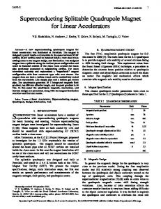
3 are shown as well (scaled by 245/260A, due to the different solenoid design and higher maximum quench current): this was the only other device tested at 4.6 K in a cryostat, and it showed very little dependence on ramp rate [5]. Inadequate lead flow seems the most likely reason to explain this behavior, which was measured with the solenoid lead flows each at 0.04 g/s, while the dipole leads were each operated at 0.010 g/s. Later studies of the lead voltages showed that it was important to keep all of the flows high. Further investigation of the quench performance as a function of the lead flows is planned. Unlike the prototype (as in [6]), it was not possible to induce a quench in the superconducting leads by lowering the lead flows while running at 180 A. However, while testing this at very low flow (0.004 g/s/lead) the protection system accidentally tripped and caused a rapid ramp down of the current. Subsequent attempts to ramp up resulted in repeated coil quenches at the same current (84 A), indicating that some heat (e.g., due to eddy currents) was trapped in the solenoid. The only way to remove this heat was to raise all of the lead flows (0.03 g/s was sufficient) to force helium through the vessel. Afterward it was possible to power again at 180 A. As in all previously tested Type-2 solenoids, both dipoles reached 250 A without quench in the solenoid field at 180 A.
Fig. 2. Measured power lead voltage as a function of helium mass flow through the lead.
A. Quench Performance Each bare solenoid was subjected to a quench training regimen by the vendor following final welding into the helium vessel, and selected devices were re-tested at MTF to certify their performance [3]. These tests were conducted at 4.2 K and 4.4 K, respectively. Type-2 solenoid quench tests included training the solenoid to a plateau that should reach the maximum expected current based upon short sample data and the predicted load line. It also required powering the dipole coils to 250 A with the solenoid powered at the nominal 180 A operating current.The first production Type-2 solenoid (T2_01) had been previously tested at MTF, and was chosen for assembly into HCHB01, the first production cryostat assembly. For HCHB01, the quench test was conducted first, before thermal studies. The quench performance shows evidence of less than ideal cooling conditions. The solenoid reached a quench plateau without re-training, but about 3 % below the expected level, and exhibited very strong dependence on ramp rate which was not seen in any previous tests. Fig. 3 illustrates the quench behavior at 1 A/s ramp rate of HCHB01 along with those Type-2 solenoids re-tested at MTF, and with a temperature-dependence prediction. The HCH-P-001 data
Fig. 3. Quench current versus temperature for HCHB01, HCH-P-001, and other Type-2 CH solenoids.
A. Alignment As with the prototype cryostat solenoid [5], alignment measurements were made using Single Stretched Wire (SSW) techniques, which allow wire positioning control at the level of 1 micron. A Vibrating Wire (VW) technique [8] was developed and tested on the prototype. Compared to the Moving Wire (MW) method, the VW gives more accurate results, chiefly because it is able to reduce systematic errors caused by the proximity of the stages to the magnet ends. The ends have relatively large fringe fields in the vicinity of the stage surfaces (~50G at operating current) where the return wire is attached. The return wire therefore cuts flux lines during measurements when it rather needs to be stationary throughout the field of the magnet. The VW approach has no such complication since the mechanical vibrations are measured only on the stretched wire itself. In principle, the VW can be operated at various frequencies to excite multiple oscillation modes, thereby giving some ability to explore the axial (Z) dependence of the center – whose position may vary due to bucking and main coil offsets at the ≤ 250 micron level
5LPM-01 during fabrication. This extended capability has not yet been explored for these magnets. To understand the changes and reproducibility of warm to cold solenoid axis positions, measurements were made over two thermal cycles. The results of alignment measurements during the various thermal cycles are shown in Figures 4 and 5, relative to the axis position during the first cold test (chosen as the zero axis). Here X is the horizontal axis, Y is the vertical axis, and Z is the axial direction. Note that the axis has been projected to points at Z= ± 105mm (corresponding roughly to the axial ends of the cryostat) to indicate the pitch/yaw present. Measurements taken to determine whether there was a dependence on the XY center offset vs. magnet current showed no measureable result – the center appears to be stable at the resolution of the measurements (< 10 microns).
4 solenoid excitation at 12 A that allows good noise rejection. As mounted on the test stand (not yet converted to cryostat coordinates using survey) the Horizontal Dipole field angle was -12.83±0.17 mrad from vertical, and the Vertical Dipole found to be +4.97±0.02 mrad from horizontal. Thus these two dipoles are about 1 degree short of being perfectly orthogonal. For cold measurements the DC signals very weak: with transfer functions of about 0.05 T-m/kA, the signal size is small even at 200 A. Combined with the small aperture that limits wire motion, this leads to an angle resolution of about 2.5 mrad. However, it became clear that the situation is complicated by relatively large magnetization effects in the superconductor: both the transfer functions and field angles are affected by the ramp history of both coils. The magnitude of the magnetization field is equivalent to powering the coil at about 6 A. Further studies are required to better understand the dipole correctors and how they might perform when used as planned for the beam line. V. CONCLUSION Testing of the first Type-2 production cryostatted solenoid focusing lens for the HINS R&D proton linac is under way. A first pass has been made to evaluate the thermal, quench, and alignment performance. Results so far are in reasonable agreement with expectations, but some additional studies are planned to resolve some puzzles in each of these areas, and establish the best conditions for operation in the beam line. Testing of the first Type-1 production lens will occur soon, as the assembly is nearing completion.
ACKNOWLEDGMENT Fig. 4. Summary of solenoid horizontal axis position during cold/warm conditions relative to the alignment made at 4.4K during the first test cycle.
The authors wish to thank the staff at the Fermilab Magnet Test Facility and Magnet Systems Department for their excellent technical advice and support throughout this program. REFERENCES [1] [2]
[3]
[4] [5]
[6] Fig. 5. Summary of solenoid vertical axis position during cold/warm conditions relative to the alignment made at 4.4K during the first test cycle.
[7] [8]
Dipole strength and field angles were also studied with the MW technique, both warm and during the first cold cycle. The warm measurements are well determined by using an AC
G. Apollinari, et al., “HINS Linac Front End Focusing System R&D,” IEEE Trans. Appl. Supercon., Vol. 19, No. 3, June 2009, pp.1368-1371. T. Nicol, et al., “Design and Performance of Focusing Lenses for Installation into Superconducting Cryomodules of a Proton Linac,” 5LPM-02, submitted to this conference. M. Tartaglia, et al., “Summary of HINS Focusing Solenoid Production and Tests,” IEEE Trans. Appl. Supercon., Vol. 20, No. 3, June 2010, pp.312-315. T. Page, et al., “High intensity neutrino source superconducting solenoid cryostat design,” AIP Conf. Proc. Vol. 985, March 2008, pp341-348. T. Page, et al., “HINS Superconducting Lens and Cryostat Performance,” IEEE Trans. Appl. Supercon., Vol. 19, No. 3, June 2009, pp.1356-1359. D. Orris, M. Tartaglia, “Superconducting Strand Quench Development Tests,” Technical Division Note TD-09-012, FNAL, April 2009. J. DiMarco, et al., “Performance Test of HCHB01,” Technical Division Note TD-10-018, FNAL, July 2010. A. Temnykh, “Vibrating Wire Field-measuring Technique”, Nucl. Instr. and Methods in Physics Research A 399, 1997, pp185-194.