1: Complete 3-D Assembly of stay ring, distributor, runner and draft tube of axial flow Kaplan Turbine ... distributor and draft tube are fixed and runner is rotating.
Dr. Vishnu Prasad, Dr. Ruchi Khare / International Journal of Engineering Research and Applications (IJERA) ISSN: 2248-9622 www.ijera.com Vol. 2, Issue 4, July-August 2012, pp.1029-1035
CFD: An Effective Tool for Flow Simulation in Hydraulic Reaction Turbines Dr. Vishnu Prasad*, Dr. Ruchi Khare** *Department of Civil Engineering, M.A. National Institute of Technology, Bhopal-51 **Department of Civil Engineering, M.A. National Institute of Technology, Bhopal-51
ABSTRACT The reaction turbines have application in very wide range hydro power projects. The turbines are the most important components of any hydro power plant. Its cost varies 15-35% of the total cost of hydropower project. Thus the cost effective design of the turbine is of utmost importance. It is very crucial to understand the flow behavior of the turbine under various operating conditions. The model testing of turbines give overall performance of turbines based on global parameters. This approach is very costly and time consuming. But the detailed analysis of the performance of turbine is important under off-design and overloading conditions. Now-a-days computational fluid dynamics compliments experimental and theoretical approach by providing an alternate cost effective means of simulating real flow as it is much cheaper than experimental testing. In the present paper, the numerical flow simulation in reaction turbines ie, the axial and mixed flow turbines has been carried out to study effect of operating conditions on the local and global parameters of turbine. The simulation results for efficiency and output bear close comparison with experimental results.
Key-words; axial flow turbine, CFD, mixed flow turbine, reaction turbines, runner I. INTRODUCTION The turbines are designed for particular values of global and local design parameters based on assumptions but most of time, turbine operates at off-design conditions which affects its performance. The overall performance of the turbine depends on the individual performances of each component. The change in guide vane opening leads to variation in discharge and flow direction, which in turn leads to the variation of flow parameters in different components of turbine. Similarly, variation in rotational speed of runner also affects the flow characteristics, especially, in the runner [1]. The conventional practice to predict the performance of turbine is testing of scaled models manufactured satisfying hydraulic similitude. The model testing gives the global performance but is unable to identify the causes of poor performance of turbine. This is also time consuming and costly. The theoretical approach for flow analysis in individual components of the turbine was used to estimate the losses and flow behavior. With the advancement in numerical techniques and power of computer have made computational fluid dynamics (CFD) a cost effective tool to provide detailed flow information inside the complete turbine space. The flow simulation in turbine space as a whole take care for the interactions between different components.[7]. Most of the turbine designers and researchers use CFD for optimization of its design and for prediction of performance of reaction turbine in terms of local and global parameters [5]. The detailed information on flow and cascade parameters under different operating conditions is still being worked out by various investigators. In the present work, numerical flow simulation in reaction turbines both in axial and mixed flow turbine, for different geometric configuration of guide vane and rotational speed of runner has been carried out using commercial CFD code Ansys CFX. The variation of efficiency and discharge with speed factor are presented in graphical form. The pressure and velocity distribution at runner blade for both type of turbines are also presented. The CFD results for efficiency and discharge are in closed comparison with experimental results [2,4].
II. GEOMETRY AND MESH GENERATION In the present work two turbines, axial flow turbine and mixed flow turbine are used for the analysis. .
1029 | P a g e
Dr. Vishnu Prasad, Dr. Ruchi Khare / International Journal of Engineering Research and Applications (IJERA) ISSN: 2248-9622 www.ijera.com Vol. 2, Issue 4, July-August 2012, pp.1029-1035
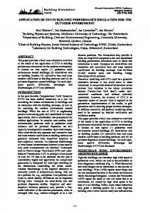
Fig. 1: Complete 3-D Assembly of stay ring, distributor, runner and draft tube of axial flow Kaplan Turbine
The modeled axial flow turbine (Fig.1) consists of a stay ring having 12 stay vanes, a distributor having 28 guide vanes, a runner with 4 blades and an elbow draft tube. The turbine space is divided in 4 domains, stay vane, distributor and draft tube are fixed and runner is rotating. Casing is not considered for analysis because of limitation of computational facility. In mixed flow turbine (Fig.2) consists of 18 stay vanes in stay ring, 18 guide vanes in distributor, runner with 13 blades and conical elbow draft tube. The complete flow domain for both turbines is discretized into small elements through tetrahedral unstructured meshing.
Fig. 2: Complete 3-D Assembly of stay ring, distributor, runner and draft tube of mixed flow Francis Turbine In case of axial flow turbine the numerical simulation is carried out for 3 guide vane openings i.e. 35˚, 40˚ and 50˚ from tangential direction and 8 rotational speeds between 900 rpm and 1400 rpm whereas, for mixed flow turbine, the simulation is done for three guide vane openings i.e. 66.73 mm, 80.93 mm and 91.57 mm and 6 rotational speeds
1030 | P a g e
Dr. Vishnu Prasad, Dr. Ruchi Khare / International Journal of Engineering Research and Applications (IJERA) ISSN: 2248-9622 www.ijera.com Vol. 2, Issue 4, July-August 2012, pp.1029-1035 between 600 rpm and 900rpm. SST k-ω model is used for the simulation. The y-plus value is found to be less than 200, which is within the acceptable limit.
III. FORMULAE USED Net Head
Hydraulic efficiency Speed factor Discharge factor
H=
TPi -TP0 γ
H-H l -100 H nD nq = H Q Qq = 2 D gH ηh =
Pressure coefficient
Cp2 =
Specific velocity
c=
p-p2 1 ρW 2 2 2
C 2gH
(1)
(2) (3) (4)
(5)
(6)
IV. RESULTS AND DISCUSSIONS The variations of efficiency with speed factor for axial and mixed flow turbines are shown in fig. 3 and fig. 4. It is depicted that the best efficiency point in axial flow turbine occurs at higher speed factor than mixed flow turbine. The efficiency at off-design condition is seen better in axial flow as compared to mixed flow turbine.
Fig.3: Variation of efficiency in axial flow turbine
Fig.4: Variation of efficiency in mixed flow turbine
1031 | P a g e
Dr. Vishnu Prasad, Dr. Ruchi Khare / International Journal of Engineering Research and Applications (IJERA) ISSN: 2248-9622 www.ijera.com Vol. 2, Issue 4, July-August 2012, pp.1029-1035
Fig.5: Variation of discharge in axial flow turbine
Fig.6: Variation of discharge in mixed flow turbine
In case of axial flow turbine, the discharge increases continuously with increase in rotational speed at all GV openings as seen in fig.5 whereas in fig.6 for mixed flow turbine, it is slightly affected by runner speed but at higher speed, discharge reduces due to centrifugal force. The discharge increases with guide vane opening in both types of turbines due to increased flow area. As shown in fig. 7, the blade loading i.e. pressure distribution at pressure and suction surface of runner increases with increase in GV opening and there is smooth variation except at hub region due to hub curvature for axial flow turbine and variation in pressure from leading edge (LE) to trailing edge (TE) is very gradual. But in mixed flow turbine, there is sharp variation in pressure from LE to TE as seen in fig.8 indicating more accelerating flow from LE to TE. There is smooth distribution pattern on most of the blade surface in both the turbine except LE and TE region and it may be due to mismatching of actual flow and blade angles especially at off-design regimes.
Fig.7: Variation of pressure in axial flow turbine
Fig.8: Variation of pressure in mixed flow turbine
1032 | P a g e
Dr. Vishnu Prasad, Dr. Ruchi Khare / International Journal of Engineering Research and Applications (IJERA) ISSN: 2248-9622 www.ijera.com Vol. 2, Issue 4, July-August 2012, pp.1029-1035 Table 1 - Average values of velocity triangles parameters at three GVO in axial flow turbine GVO =40 GVO =35 GVO = 50 Parameters
Inlet
Outlet
Inlet
Outlet
Inlet
Outlet
c
0.596
0.368
0.584
0.422
0.573
0.483
cu
0.475
0.080
0.419
0.070
0.338
0.032
cm
0.343
0.351
0.395
0.387
0.459
0.461
W
0.784
1.411
0.935
1.238
1.257
1.527
23.68
17.73
27.65
18.27
33.44
17.88
Table 2 - Average values of velocity coefficients and flow angles for three GVO in mixed flow turbine GVO= 66.73mm
GVO = 80.93mm
GVO = 91.57mm
Parameters Inlet
Outlet
Inlet
Outlet
Inlet
Outlet
c
0.670
0.352
0.641
0.325
0.616
0.332
cu
0.628
0.217
0.580
0.136
0.534
0.076
cm
0.233
0.278
0.275
0.295
0.309
0.324
w
0.387
0.558
0.448
0.590
0.516
0.653
36.55
29.88
37.905
29.989
36.726
29.718
The specific values of all velocity triangles components in case of axial turbine at constant rotational speed of runner are shown in Table 1 depicts that at inlet whirl velocity and absolute velocity decrease with guide vane opening while meridional , relative velocity and flow angle increase with guide vane opening. But at outlet absolute velocity, meridional velocity and relative velocity increases and whirl velocity decreases with increase in guide vane opening. It is observed from Table 2 that in case of mixed flow turbine, both at inlet and outlet absolute and whirl velocities are decreasing while meridional and relative velocities are increasing with increase in guide vane opening. The flow angles are nearly independent of guide vane opening. Fig. 9 and fig.10 shows the pressure contours at the meridional space of axial and mixed flow turbine. It is observed that there is pressure across the runner in both the turbines. The pressure drop from inlet to outlet of runner in case of mixed flow turbine (fig. 9) is seen to be more in comparison to that in axial flow turbine (fig. 10). It may be because of the twisted shape of the runner blades of mixed flow turbine runner.
1033 | P a g e
Dr. Vishnu Prasad, Dr. Ruchi Khare / International Journal of Engineering Research and Applications (IJERA) ISSN: 2248-9622 www.ijera.com Vol. 2, Issue 4, July-August 2012, pp.1029-1035
Fig.9: Pressure contours at meridional space of axial flow turbine
Fig.10: Pressure contours at meridional space of mixed flow turbine
V. CONCLUSION The efficiency and discharge variation obtained from simulation results of both axial and mixed flow turbine depicts the characteristics of reaction turbine obtained from experimental model test results. The drop in pressure from inlet to outlet of runner and increase in relative velocity indicate the reaction of water on runner blades. The reduction of whirl component from inlet to outlet also confirms the design features of a reaction turbine. The performance of axial flow turbine at off design regime is better in mixed flow turbines. The CFD can be used as a tool for performance evaluation and to predict the detailed flow pattern at different operating regimes effectively to minimize the model testing. Nomenclature c - specific absolute velocity cm - specific meridional velocity cu - specific whirl velocity D - diameter of runner (m) g - acceleration due to gravity (m/sec2) H - net head (m) Hl - total head loss (m) n - rotational speed of runner (rpm) p - static pressure at any section of runner blade (pa)
1034 | P a g e
Dr. Vishnu Prasad, Dr. Ruchi Khare / International Journal of Engineering Research and Applications (IJERA) ISSN: 2248-9622 www.ijera.com Vol. 2, Issue 4, July-August 2012, pp.1029-1035 p2 Q TPi TPo w W2 γ β
- static pressure at outlet of runner (pa) - discharge (m3 /sec) - total pressure at stay vane inlet (pa) - total pressure at draft tube outlet (pa) - specific relative velocity - relative velocity at outlet of runner(m/s) - specific weight (N/m3) - relative flow angle from tangential direction at runner inlet(degrees)
References [1]. [2]. [3]. [4]. [5]. [6]. [7].
Barlit V.V., Krishnamachar P., Deshmukh M.M., Swaroop Adarsh, Gehlot V.K., Hydraulic Turbines Volume I&II, ( MACT, Bhopal, 1983) Khare Ruchi, Vishnu Prasad and Sushil Kumar, Derivation of Global Parametric Performance of Mixed Flow Hydraulic Tubine, International Journal of Hydro Nepal, Issue(7),2010, pp 60-64. Nechleba M, Hydraulic Turbines-Their Design and Equipment (Artia Prague, Czechoslovakia,1957) Prasad Vishnu, Gahlot V.K., Simplified CFD Approach For Design Optimisation Of Axial Flow Hydraulic Turbine Runner, CURIE Journal, Birla Institute of Technology, Pilani ,2009 Rajoo Srihar, Ricardo Mcerinez Botas, Mixed flow Turbine Research: A Review, Journal of Turbo Machinery, Vol. 130(10), pp 044001-1 to 044001-12, 2008 Saeed R.A., Galybin A.N. and Popov V., 2010, Modeling of Flow Induced Stresses in a Francis Turbine Runner, Elsevier on line Journal, pp 1-11 Wu Jingchun, Shimmel K, Tani K., Niikura K. Sato, J, 2007, CFD-Based Design Optimization for Hydro Turbines, Journal of Fluid Engineering, Transactions of ASME, Vol.127, pp159-168, 2007
1035 | P a g e