PROCEEDINGS, Thirty-Third Workshop on Geothermal Reservoir Engineering Stanford University, Stanford, California, January 28-30, 2008 SGP-TR-185
CHALLENGES FOR GEOTHERMAL ENERGY UTILISATION Hal Gurgenci1,2, Victor Rudolph2, Tapan Saha2, and Max Lu2 1
Acting Director, Queensland Geothermal Energy Centre of Excellence The University of Queensland, St Lucia, Queensland 4072, Australia e-mail:
[email protected]
2
ABSTRACT The Queensland Government recently awarded A$15 million to the University of Queensland to establish a new “hot rocks” research and development centre, called the Queensland Geothermal Energy Centre of Excellence. The vision for the Centre is to provide urgent, forward looking research, development and support for establishment of geothermal energy as a clean energy option through a program of research, development and skills capacity building that will be linked with other major research providers nationally and internationally.
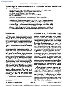
Geothermal Energy in Australia Numerous past studies estimate existence of substantial geothermal resources for Australia, e.g.. In many areas of Australia, the estimated temperatures at a depth of 5 km exceeds 250 oC as shown in Figure 1 extrapolated from a database of temperatures recorded in 3291 wells. While the Great Artesian Basin appears as the largest hot rock area in Figure 1, there are other areas, e.g. the area labelled as A in the figure which is in the heart of a major coal mining district and close to large coalfired power stations.
The Centre is currently developing a road map for its next five years. This paper will report on that process and should be recognised as “work in progress.”
Figure 1: The estimated temperature at a depth of 5 km in the Australian continental crust calculated from the database of (Somerville et al. 1994) by (Swenson, Chopra & Wyborn 2000)
There are nine Australian companies listed on the stock exchange with a combined market capitalisation of over A$700m. The most significant advancement in terms of the potential of hot rock geothermal energy in Australia is the drilling of the Habanero wells by Geodynamics. The Australian geothermal energy industry is described in greater detail in another paper presented in this workshop(Goldstein et al. 2008).
the existing research line-up in Australia and around the world.
The bulk of the Australian geothermal resource seems to be under a horizontal stress regime with both the major and intermediate principal stresses defining a near-horizontal plane. Such a stress field would suggest a subhorizontal (close to horizontal) reservoir zone after the stimulation. Early seismic results from Habanero-1 seemed to support this hypothesis. A horizontal reservoir is favoured because of the relative ease of adding new wells to an existing network of cells and the ability of the reservoir to contain water. On the downside, higher injection pressures might be necessary to open up against the subvertical minimum principal stresses, which are expected to be roughly equal to the lithostatic pressures at that depth.
This paper will try to develop some concepts for these four programs, with an emphasis on the first one.
The experience with Habanero-1 so far has confirmed these predictions. An examination of the induced seismicity during hydraulic stimulation indicates the existence of a large subhorizontal fracture zone dominating the stimulated reservoir(Baisch et al. 2006).
Queensland Geothermal Energy Centre of Excellence In September 2007, responding to a proposal from The University of Queensland (UQ), the Queensland State Government committed A$15 million to the Queensland Geothermal Energy Centre of Excellence at UQ, Brisbane. This is being met by a A$3.3 million contribution of expertise and other resources from UQ, making this the largest investment in geothermal energy research in Australia. The Centre will carry out original R&D and will work with Australian and overseas universities and research institutions to expedite the development and adoption of geothermal energy in Australia. The Centre is currently developing a road map for its next five years with a focus on surface plant and power generation and transmission technologies and equipment while maintaining a watching brief on the subsurface issues. This choice of focus does not necessarily reflect the ranking of surface and subsurface issues for the Australian or global geothermal industry but to fill in significant gaps in
The work will be conducted under four program headings: o Power conversion o Air-cooled heat exchangers o Reservoir management o Power generation and transmission
Power Conversion The cost of the surface installations, the power conversion and auxiliary systems, is over 60% of the total cost of a geothermal power plant. There seems to be a myth that power conversion is a mature technology with little room for improvement. Due to this myth and also due to the obvious and enormous risks associated with the subsurface reservoir assessment and development, almost the entire noncommercial and pre-commercial geothermal energy research and development over the past twenty years have been directed towards subsurface issues, namely discovery, characterisation, development, and exploitation of the underground geothermal resource. This research is certainly of critical importance to the future of geothermal energy, as one of the major problems facing the industry today is to convince financial backers that the risk in geothermal investment is quantifiable and acceptable. Any work towards a better understanding and control of this risk is immensely important. However, it should also be recognised that higher risks are entertained when the probable rewards are higher. The work on power conversion and associated auxiliary systems such as condensers is directed towards increasing these rewards. For example, imagine 50% increase of the generated electricity for the same subsurface investment. This would encourage one to take higher risks. It is not a pipe dream. There is no theoretical reason why the geothermal power plants should not be achieving the same ratio of their theoretical limit as the steam plants do. If geothermal plant technology achieves the same maturity as the steam power plants so that they enjoy similar ratios of the theoretical limits, their electrical output could increase by 50% above the present levels for the same subsurface investment. Obviously, this would have a significant effect on whether a geothermal project is backable and at what subsurface risk level. Even in instances where subsurface heat exchange issues are under control, geothermal energy will not
become a competitive electrical power generation alternative unless we realise a significant improvement on the efficiency of converting geothermal heat into mechanical torque on the generator shaft. According to the second law of thermodynamics, heat must be transferred between hot and cold reservoirs to produce mechanical work. The thermal efficiency is defined as the produced mechanical power divided by rate of heat input into the cycle working fluid. The theoretical limit on thermal efficiency is the efficiency of the Carnot cycle, which represents ideal power conversion conditions: T ηc = 1 − C (1) TH The hot fluid temperature, TH, is set by the quality of the resource and the cold temperature, TC, is determined by the ambient temperature and the availability and the temperature of cooling water. The theoretical efficiencies are low in geothermal because of the temperatures. The situation is however much worse than that because, compared to the steam power plants, only a relatively small fraction of this theoretical limit is obtained in existing geothermal practice. This is shown in Figure 2. The hot fluid temperature (TH) and thermal efficiency (ηth) data used in this figure are from (Tester 2006) and the cold temperatures (TC) are the average ambient temperatures around these power plants as determined from the meterological data published on the web by various agencies (too numerous to list). The Carnot efficiency is calculated using equation (1).
comparison, the efficiencies enjoyed in modern steam power plants are around 60% of the ideal efficiency referring to those conditions. Clearly, there is room to improve in geothermal power plant technology. Such major improvements cannot be obtained by incremental changes to existing power plant technology. New paradigms are needed in the following areas: o New cycle options – e.g. supercritical cycles o New cycle fluids o Possibly new turbine/expander designs optimised for geothermal fluids An interesting idea is the use of CO2 as the cycle fluid. The use of CO2 as the geothermal heat exchange fluid was proposed by (Brown 2000) and (Pruess 2006). They limited CO2 to subsurface heat exchange and assumed a standard binary plant. We believe there is a significant potential for the use of CO2 also as a power cycle fluid. In fact, we predict significantly higher efficiencies using a single loop with the CO2 as both the heat exchange and the power cycle fluid. Figure 3 shows the essentials of such a system. 6
5 T
P
4
1
5000 m
50 45
Table 3.1, Tester Report (2006) + Climate data from the web for TC
3
ηth, ηcarnot, and ηth/ ηcarnot
40 35
CO2
ηth/ ηcarnot
30 25
Figure 3: A single-loop system where CO2 is both the heat exchange and the power cycle fluid.
ηcarnot
20
2
15 10
ηth
5 0 0.64
0.66
0.68
0.7
0.72
0.74
0.76
0.78
0.8
0.82
TC/TH (oK/ oK)
Figure 2: Actual and ideal power conversion efficiencies observed in existing geothermal practice. The important message from Figure 2 is that less than 40% of the ideal efficiency is realised in actual geothermal practice and the ratio is as low as 30% for low reservoir or high ambient temperatures. In
Such a system could use a supercritical Rankine or a supercritical Brayton cycle. The former has a condenser, the latter always operate in supercritical region. This choice is determined by the value of the pressure at point 5. In the following analysis, we ignore all frictional losses, including the pressure drop across the reservoir. Then the thermosiphon effect between the injection and production wells becomes sufficient to drive the loop. This is certainly not going to be case in an actual plant especially due to the frictional pressure drop through the reservoir but it is
interesting to observe the significance of the buoyancy effect. Under these circumstances, the pressure at point 5, p5, is the same as p6 and p1. Before we can draw the temperature-entropy diagram for a supercritical Rankine cycle, we need to analyse the distribution along the injection and production wells. For the purpose of this paper, we will start with the injection well conditions as assumed in (Pruess 2006): p1=5.7 MPa and T1=20oC, very close to saturated liquid conditions. As a first approximation, we assume reversible adiabatic (isentropic) flow in both wells. We start with the first law of thermodynamics written over an infinitesimal element along the well as shown in Figure 4, qi + hi +
Vi 2 V2 + g ∆z = h2 + i +1 2 2
(2)
The heat transfer term, qi is zero (reversible adiabatic flow). The velocity is not necessarily constant because the density increases as we go deeper.
by using the MATLAB fminsearch function. The function fminsearch finds the minimum of a scalar function of several variables, starting at an initial estimate. This function uses a form of simplex search method. The state equations were also coded in Matlab using the formulae and coefficients by (Span & Wagner 1996). The subsurface heat transfer is assumed to occur at constant pressure to bring the fluid from T2 up to the reservoir temperature, T3. Knowing both p3 and T3, The thermodynamic state at Point #3 is determined by inverting the equation p=p(ρ,T). The expansion along the production well is treated in a similar way but in reverse. This determines the state at Point #4. The turbine work is the result of isoentropic expansion from #4 to #5 and the thermodynamic state at #5 is determined from the two properties known at this point: s5 (=s4) and p5 (=p1). This completes the cycle and allows us to plot the temperature-entropy diagram as shown in Figure 5 and calculate the efficiency as qh ( s4 − s2 )(T4 + T2 ) / 2 = (9) wt h4 − h5 The thermal efficiency for the cycle shown in Figure is calculated as 29.5%. Even taking into account the parasitic losses that will occur in a real cycle, this is a high efficiency achieving 69% of the ideal limit.
ηth =
Vi pi
i ∆z i+1
pi+1
L
While the supercritical Rankine cycle using CO2 has a high efficiency, this cycle is only appropriate in sites with the ambient temperature well below the supercritical temperature of CO2 (31oC) or with access to ample quantities of cooling water. Otherwise, a supercritical Brayton cycle could be more appropriate as shown in Figure 6.
Vi+1
Figure 4. An infinitesimal element along the geothermal well. The pressure, pi+1, and enthalpy, hi+1, at each element, are found in this fashion. The other thermodynamic properties are found by inverting the state equations h(ρ, T) and p(ρ, T) to solve for ρ and T. We do this by finding the (T,ρ) pair that minimises the error function Ε = ( hi +1 − h( ρ , T ) ) + ( pi +1 − p ( ρ , T ) ) 2
2
(8)
In a supercritical Brayton cycle, there is no condensation and the supercritical fluid is cooled from #5 to #1 in Figure 6. The efficiency is calculated as 23.7% based on the injection conditions of 8MPa and 47oC and the same reservoir temperature as in Figure 5. Deterioriation in the efficiency is significant but not critical and reflects the increased value of the cold temperature rather than the fundamental differences between the two types of cycle.
550
500
48.1 MPa 235 oC
Thermal efficiency=29.5%
4
450
26.2 MPa
o
Temperature, K
3
400
350 48.1 MPa
2 5
300
1
5.7 MPa
o
20 C
5.7 MPa 250
200 -2.6
-2.4
-2.2
-2
-1.8
-1.6
-1.4
-1.2
-1
-0.8
-0.6
o
Entropy, kJ/kg- K
Figure 5: Supercritical Rankine cycle in a geothermal application using CO2. supercritical-loop 550
500
25 MPa, 508 oK
Thermal efficiency=23.7%
Temperature, oK
450
3
13 MPa 4 25 MPa, 408 oK
400
2 5
8 MPa 350 8 MPa 320 oK 1 300
250
200 -2.6
-2.4
-2.2
-2
-1.8
-1.6
-1.4
-1.2
-1
Entropy, kJ/kg-oK
Figure 6: Supercritical Brayton cycle in a geothermal application using CO2
Figure 7: Variation of supercritical Brayton efficiency with the turbine exit pressure
-0.8
-0.6
Figure 8: Two Brayton cycles with two different turbine exit pressures.
An auxiliary benefit of using CO2 as the heat exchange fluid raised by (Pruess 2006) is the likely sequestration of some of the CO2 through losses to the reservoir. It is difficult to estimate this amount but based on the past experience with water-filled reservoirs, it could be significant. It is also worth noting that the loops in either of the two cycles above do not have to be closed. If there is ready access to CO2 (for example, at a geothermal installation situated close to a coal-fired power plant), the captured CO2 can be run through the geothermal reservoir first and then sequestered in a sequestration site of choice. From a geothermal power plant cost and efficiency point of view, this would have the advantage of removing the condenser step (or the cooling in the Brayton cycle) thus reducing the parasitic losses. This substantial benefit would be achieved at no extra cost provided the coal-fired plant carbon-capture-storage decision is already made based on other considerations. Before we leave this topic, it is worth noting that, in the supercritical Rankine cycle, the low-side pressure and temperature are related through the saturation relationship. This constraint does not apply to the Brayton cycle and there is some flexibility in selecting the operating pressure independently of the temperature of the cooling medium. The cycle efficiency is however the highest when the heat removal occurs at near-critical pressures. The compressor work is also highest at this region but this is compensated by the higher turbine work. These effects are shown in Figures 7 and 8.
Air-Cooled Heat Exchangers A 500 MW geothermal plant in a desert area will need to be very efficient at condensing the working fluid. Evaporative cooling with water is no longer acceptable in the Australian power supply context and certainly not in the Cooper Basin due to lack of water. Cooling systems have attracted virtually no advances in scores of years, with scientific literature in the last 10 years limited to parametric optimisation studies(Conradie, Buys & Kroger 1998; Conradie & Kroger 1996). Dry cooling is disadvantaged by severe cycle efficiency penalties. Given that advances in cooling also have spin-off benefits for conventional power plants, the Centre will have a significant focus on creative and novel platforms for cooling systems. Examples might include vortex tube cooling (which provides air at below 0 oC with no moving parts), night-time radiative cooling with cold stores, draft towers and high efficiency, novel heat transfer technologies such as printed circuit heat exchangers or nano-particle enhanced cooling fluids. Reservoir management There is no question that this is an area where the greatest challenges lie for the geothermal industry. These could be grouped under the following headings with a loose set of ideas listed under each heading with no claim to be exhaustive. o Reservoir modelling – while there is room for expanding the capabilities of existing models (e.g. rock-fluid mechanical and chemical interaction) the need here is to develop techniques for model updating based on field measurements o Data fusion and information modelling using geological knowledge, exploration data, downhole geophysics and other data, seismic
o
o
monitoring, and all other available current and historical information Technologies to develop and steer fracture networks o placement and detonation of controlledrate explosives o smarter tracers Technologies to recover from mistakes, e.g. short-circuits.
The Centre will address these issues in collaboration with Australian and overseas universities, research institutions, and the industry. Power generation and transmission When a 500 MW power plant (geothermal or coal fired) is located faraway from major load centres and also from the national electricity grid, a number of important power transmission issues need to be investigated. When the transmission line is long (e.g. in this case more than 500 km), the reactive power loss and hence voltage stability issue becomes extremely important to maintain the power grid security. In addition, possibility of inter area frequency oscillation can't be ignored and the use of flexible AC transmission system or high voltage (HV) DC transmission system needs to be examined. In a deregulated electricity market with a foreseeable carbon trading scheme a number of relevant nontechnical issues also need to be investigated.
The Centre will research issues relating to: o grid stability, thermal, reactive power and voltage limits o inter area frequency oscillation o HVAC versus HVDC, regarding cost and network security o storage and adequacy, including corridor congestion, dispatch patterns and interaction with trading systems o market designs and validation within a carbon trade environment Conclusions Significant improvements in power conversion technologies are possible and will make geothermal energy more competitive. In this paper, we identified some of the opportunities that will be pursued by the Queensland Geothermal Energy Centre of Excellence. Acknowledgements We acknowledge the support of Queensland State Government in making this research possible. References Baisch, S, Weidler, R, Voros, R, Wyborn, D & de Graaf, L 2006, 'Induced seismicity during
the stimulation of a geothermal HFR reservoir in the Cooper Basin, Australia', Bulletin of the Seismological Society of America, vol. 96, no. 6, pp. 2242-56. Brown, DW 2000, A Hot Dry Rock Geothermal Energy Concept utilising Supercritical CO2 instead of Water, Stanford University, Stanford, California, USA, 24-26 January 2000. Conradie, AE, Buys, JD & Kroger, DG 1998, 'Performance optimisation of dry cooling systems for power plants through SQP methods', Applied Thermal Engineering, vol. 18, no. 1-2, pp. 25-45. Conradie, AE & Kroger, DG 1996, 'Performance evaluation of dry cooling systems for power plant applications', Applied Thermal Engineering, vol. 16, no. 3, pp. 219-32. Goldstein, BA, Hill, AJ, Budd, AR, Holgate, F & Malavazos, M 2008, 'Hot Rock Geothermal Plays in Australia', paper presented to Annual Stanford Workshop on Geothermal Reservoir Engineering, Stanford, California, USA, 28-30 January 2008. Pruess, K 2006, 'Enhanced geothermal systems (EGS) using CO2 as working fluid—A novel approach for generating renewable energy with simultaneous sequestration of carbon', Geothermics, vol. 35, pp. 351-67. Somerville, M, Wyborn, D, Chopra, PN, Rahman, SS, Estrella, D & Meulen, Tvd 1994, Hot Dry Rocks Feasibility Study, 94/243, ERDC Australia. Span, R & Wagner, W 1996, 'A New Equation of State for Carbon Dioxide Covering the Fluid Region from the Triple-Point Temperature to 1100 K at Pressures up to 800 MPa', J. Phys. Chem. Ref. Data,, vol. 25, no. 6, pp. 1509-96. Swenson, D, Chopra, P & Wyborn, D 2000, 'Initial Calculations of Performance for an Australian Hot Dry Rock Reservoir', paper presented to World Geothermal Congress 2000, Kyushu-Tohokum Japan, May 28June 10, 2000. Tester, JW 2006, The Future of Geothermal Energy, MIT, Boston.