Gábor Bergmann1, István Ráth1, Gergely Varró2, Dániel Varró1. 1 Budapest University of ...... update queries is a syntactic sugar. While it helps to con-.
Software and Systems Modeling manuscript No. (will be inserted by the editor)
Change-Driven Model Transformations Change (in) the Rule to Rule the Change G´ abor Bergmann1 , Istv´ an R´ ath1 , Gergely Varr´ o2 , D´ aniel Varr´ o1 1
2
Budapest University of Technology and Economics, Department of Measurement and Information Systems, H-1117 Magyar tud´ osok krt. 2, Budapest, Hungary Technische Universit¨ at Darmstadt, Real-Time Systems Lab, DE-64283 Merckstr. 25, Darmstadt, Germany
Received: date / Revised version: date
Abstract In the paper, we investigate change-driven model transformations, a novel class of transformations, which are directly triggered by complex model changes carried out by arbitrary transactions on the model (e.g. editing operation, transformation, etc). After a classification of relevant change scenarios, we identify challenges for change-driven transformations. As the main technical contribution of the current paper, we define an expressive, high-level language for specifying changedriven transformations as an extension of graph patterns and graph transformation rules. This language generalizes previous results on live model transformations by offering trigger events for arbitrarily complex model changes, and dedicated reactions for specific kinds of changes, making this way the concept of change to be a first-class citizen of the transformation language. We discuss how the underlying transformation engine needs to be adapted in order to use the same language uniformly for different change scenarios. The technicalities of our approach will be discussed on a (1) model synchronization case study with non-materialized target models and (2) a case study on detecting the violation of evolutionary (temporal) constraints in the security requirements engineering domain. Key words incremental model transformation – change models – change-driven transformations
Acknowledgements We would like to thank the anonymous reviewers for their insightful advice. This work was partially supported by EU project SecureChange (ICT-FET-231101). The third author was partially supported by the Postdoctoral Research Fellowship of the Alexander von Humboldt Foundation and associated with the Center for Advanced Security Research Darmstadt. The fourth author was partially supported by the Janos Bolyai Scholarship.
1 Introduction The changes of models are a central issue in modeldriven software engineering (MDSE). For instance, software engineers continuously change and improve their design models using manual refinement steps or semiautomated model refactoring transformations. However, the change of one model may easily introduce inconsistencies with other models developed by other designers. In case of model-based simulation, the simulator needs to efficiently detect the changes of the underlying model (e.g. to highlight steps which can be executed at this stage). Unfortunately, the actual notion and representation of change can be very different in practical tools and scenarios. While modern domain-specific modeling environments offer an explicit set of operations, which can be executed on the model by the user in graphical editors, in many other cases, the engineers have no control over the many ways a model may change: any kind of model manipulations are possible in any sequence. In modern modeling environments (like the Eclipse Modeling Framework, EMF), elementary model changes are reported on-the-fly by some live notification mechanisms to support undo/redo operations. Model versioning frameworks persist the change history of models (history-aware log of model changes, which records causal dependency / timeliness between such changes) in the form of an external change document. Many complex refactoring operations frequently require the user to preview the requested changes (expressed as change commands) prior to actually executing them to the model. A common concept for all these cases is the change delta, which uniformly captures (the aggregated effect of) a
2
transaction which caused the model to evolve from a previous pre-state to a post-state. Furthermore, in certain complex tool integration scenarios, we receive absolutely no information about changes, i.e., changes just happen without any trace (notification or change log). Other scenarios include those with observable (but not controllable) changes. Model transformations, which consume (as input) or produce (as output) change models, in addition to the underlying models themselves, are called changedriven transformations (CDT) [1]. The practically relevant change scenarios impose additional challenges for CDTs. First, change models are typically restricted to contain elementary model changes (i.e. the creation and deletion of certain model elements); change-driven transformations, however, are frequently triggered by complex (aggregated) model changes carried out by a transaction on the model (e.g. user edit, refactoring transformation, etc), which is a key challenge. Moreover, some models can be non-materialized, i.e. when only an external interface is available for query and manipulation, which traditionally requires the development of complex adapters in the modeling environment. In addition, traceability information can also be limited and externalized (i.e. cannot be stored in the host models), which imposes further challenges. Finally, well-formedness restrictions over a trajectory of changing models can express evolutionary constraints. Despite the large variety of existing model transformation languages and tools, the concept of change is not a first-class citizen in them. In the paper, we argue that in many application scenarios, making the change as part of transformations rules is a promising approach. As a result, appropriate reactions can be based upon observing the current snapshot of the model and also the way how the model evolved. The execution mechanism of change-driven transformations also differs from traditional batch transformations. First, uncontrolled model changes (which are reported by a model management framework or detected by the CDT engine itself) happen in a transaction. Then based upon the observed changes, certain change-driven transformation rules may be triggered to manipulate the models in a controlled way. Naturally, model changes induced by these rules are transactions themselves, which may thus trigger further reactions. In this paper, (1) we propose a high-level changedriven transformation language which allows to unambiguously and succinctly capture the nature of change (as integral part of the language) and to specify the appropriate reactions. (2) Furthermore, implementation techniques of CDTs will be discussed which allow to use a single CDT language uniformly and independently from the actual change scenario and change representation including (A) internal representations (notifications of the modeling environment) vs. externalized change models, (B) forward vs. backward deltas. The concrete
G´ abor Bergmann et al.
syntax of the language is introduced as an extension to the transformation language of the VIATRA2 framework, and it generalizes previous results on live transformations [2, 3] to the complete set of change scenarios by a precise and generic formalism for change processing. The technicalities of change-driven transformations will be presented using two motivating case studies. First, in a model synchronization scenario incremental synchronization is carried out on a non-materialized target model (i.e. when only target object identifiers and a model manipulation interface of the target model are known, and the rest of the target model does not exist as an in-memory model within the transformation framework) with weak traceability links. Then, a case study from the security requirements engineering domain will demonstrate how evolutionary (temporal) requirements can be specified and incrementally evaluated using change-driven transformations. The rest of the paper is structured as follows. Section 2 provides a categorization of changes to be addressed in the paper, and details the main challenges of change-driven transformations. In Section 3, a motivating model synchronization case study is introduced as a running example for our paper. Section 4 describes the novel language for change-driven transformations. Section 5 outlines a prototype system architecture for the various cases of change scenarios. Section 6 exemplifies the use of our CDT language in the model synchronization scenario. Specifying and checking evolutionary constraints will be the goal of another case study presented in 7. Section 8 provides a detailed discussion on the advantages and limitations of our approach. Finally, Section 9 summarizes related work and Section 10 concludes our paper.
2 Overview of the approach Changes are inherent to modeling. In model-driven engineering, models are rarely static, in fact, they are evolving continuously. Most of this evolution is driven by user input in modeling environments and editors. In other cases, changes are automatically introduced by batch model manipulations such as model import, transformation and export. Change is considered to be the transition of a model from a pre-state, to a post-state, and the difference between the two is called the change delta (or model delta). This terminology is independent of the granularity and the abstraction level; it applies for changes that are just elementary model manipulation operations as well as for batch transactions or even for complex business decisions. A model-driven design setup requires these changes to be propagated along a chain of tools into derived models or generated source code. The workflow may also involve the merging of models, back-annotating the results
Change-Driven Model Transformations
of an analysis performed on a transformation’s target model to the source model, or identifying interesting or erroneous parts within models. Thus there is a need for capturing the changes precisely. In this paper, we propose a novel model transformation technology designed to address this problem by operating on changes of models as first-class citizens. We first propose (in Section 2.1) a classification scheme for changes that we aim to handle uniformly with changedriven transformations. We introduce a taxonomy that will be useful to describe which cases our change-driven transformation approach aims to deal with, and what its advantages are. Section 2.2 explains the challenges of change-driven transformations, and Section 2.3 outlines how the rest of the paper will address them.
2.1 Aspects of change We define four perspectives (control, observability, information source, delta representation), distinguishing several different ways to perceive changes to a model. An overview is shown in Fig. 1. 2.1.1 The controllability perspective There are scenarios where changes are controllable, meaning only an explicitly defined set of changes is permitted at each state of the model. A common example is when models are required to be edited exclusively using dedicated editors that only allow a limited set of high-level domain-specific model manipulations. Such modeling languages are often described by generating graph grammars [4, 5], where the grammar rules coincide with the editing rules. However, in a wider range of scenarios, the transformation designer has no control over the possible ways a model may change during its lifecycle. It can happen through manual editing in a visual tool, batch refactoring, model transformation, model merging, etc. Any type of model manipulation is possible: creation/deletion of entities and relations of arbitrary type, modifying attribute values or element names, in any arbitrary sequence, in unforeseeable ways. Furthermore, it is even possible that models temporarily violate certain domainspecific well-formedness constraints during the changes. In this case, we need to handle non-controllable changes. 2.1.2 The observability perspective After the transformation is completed and any derived model(s) are created, it is possible that the target models are changed without any model management support (e.g. when the generated source code is changed in model-to-text scenarios). When the transformation is invoked next time, it can only access the current updated version (post-state), without having any additional information sources revealing how the models were changed since the last transformation execution. In this case, the change is invisible.
3
However, with support from a model management environment, there may be ways to trace the changes made to a model, such as change logs. When the transformation system has to determine the appropriate reactions to execute, it can take advantage of such information sources. We consider the change observable if it can be deduced what the pre-state was, what change delta has been applied to it, and what the resulting post-state is. 2.1.3 The source of information perspective If the change is observable, further distinction is possible based on what kinds of information sources are available. As previously mentioned, a change consists of a pre-state, a post-state and a change delta between them. The change is observable if and only if at least two of these three information sources are directly available, since the third one can be derived. Although this derivation is possible, it might not always be efficient in an actual implementation. Therefore we distinguish three scenarios based on which two of these three information sources are available, acknowledging that each scenario offers a different kind of support for implementing change propagating transformations. A similar categorization is presented in [6]. Some model management systems may preserve a previous version of the model from the last execution of the transformation, in addition to the current version. This can be the case if version control is enabled in the model repository. When the pre-state and the post-state are directly observable, we call it the snapshot scenario (state-based in the terminology of [6]). In other situations, a description of the change may be available before it was applied on the model. An example of such a situation would be applying a patch onto the model, that consists of changes performed on a remote copy of the model. This is also the case when change requests have to be analyzed in a change management system, before the changes are actually carried out. If the pre-state and the delta are directly available, we call it the command scenario (forward delta in the terminology of [6]), and the delta can also be called a change command. Finally in the history scenario (called backward delta in [6]), the post-state is directly available along with the delta (which can be called a change history). A typical example would be manually editing a model in an editor environment, which produces notifications of the editing operations after they have been carried out, or saves transaction logs (e.g. redo stack) together with the updated version of the model. It is a rare but possible case that all three information sources are directly available (this is called the change-based case in [6]). For example, an editor may save change logs, while the model repository captures the pre-state and the post-state as well. In this case any of the implementation strategies proposed for the above
4
G´ abor Bergmann et al.
Fig. 1 Change scenarios (ignoring controllability)
three scenarios is applicable, and the choice can be made on the basis of efficiency. 2.1.4 The delta representation perspective In the history and command scenarios, the change delta is available as an information source. In this case, we define a fourth perspective that indicates how the change delta is perceived by the model transformation environment. In the documented change scenario, the delta is available as a data structure called the delta document, that specifies exactly how the pre-state and the post-state differs. One example (history scenario) is a model editor maintaining a redo log during editing, that may be retained when the model is saved. The previously mentioned change management system with change requests can be thought of an example in the command scenario. In the live change scenario, the change is experienced on-the-fly, as it happens by continuously receiving run-time notifications on the change. The notifications (e.g. method calls) can be issued before or after the actual change (command or history). The notification granularity (frequency) can range from the level of elementary model manipulations to aggregated effects of longer transactions, smoothly transitioning into the documented case. A live scenario frequently happens in model editing environments and centralized model management solutions. As a great advantage of this scenario, changes to a source model can be on-the-fly reflected in the target model, and other kinds of live transformation can be performed efficiently, facilitating valuable feedback [3, 7]. 2.2 Transformations of change Change driven model transformations are model transformations which consume changes of the host model M as input (see Fig. 2), and turn these changes into model manipulation operations, native operations (such as asynchronous messages, or external API calls), or traceability records for persistent storage of changes. Essentially, a change driven transformation rule is enabled by some changes in the host model. The actual
Fig. 2 Change-driven transformations
change representation can be of different nature (in accordance with Fig. 1), e.g. a sequence of model manipulation operations or a change delta. 2.2.1 Challenges for change-driven transformations This interpretation of change-driven transformations needs to be refined in many practical application scenarios with different model handling characteristics, which are discussed in the following. – Unified handling of complex changes in all change processing scenarios. Analogously to high-level formalisms of model and graph transformations, change-driven transformations should support a declarative, high-level specification of changes that can be seamlessly integrated into a ”host” model or graph transformation language. Moreover, this formalism (and the underlying execution semantics) should support a uniform specification and execution model for all change processing scenarios discussed previously, in order to relieve the transformation developer from a significant amount of manual coding (notification, adapters etc.), especially in the case of non-controllable changes. As an additional benefit, this independence will make a transformation portable across different change scenarios without modifying its code. The language can then be used as (i) a complete stand-alone formalism for handling model transfor-
Change-Driven Model Transformations
–
–
–
–
mation scenarios such as incremental model synchronization, model simulation (animation) in discrete systems, and on-the-fly well-formedness constraint evaluation. Additionally, (ii) it is also useful as an intermediate formalism bridging the gap between the technical challenges of the different change scenarios and high-level languages tailored for certain uses of model transformations (e.g. QVT Relations for model synchronization, or other GT-based languages for behavioral simulation). Ability to handle traditional model transformation scenarios. Ideally, the change-driven rule formalism should support traditional execution semantics as well (based on an empty pre-state), so that the rules can be used without additional changes e.g. to perform the ”first” transformation phase in model synchronization scenarios. Handling both materialized and nonmaterialized models. A typical assumption of most model transformation approaches is that the host model M is available as a materialized model in a common model store (e.g. as in-memory EMF models inside the MT framework). However, in some model transformation scenarios, this may not be technically feasible (e.g. for performance reasons – the model may be too large to fit in memory, or not trivial to import and convert). Practically, this means that only an external interface of its native environment is available for querying and manipulating M , but still using some model transformation approach is desirable to incrementally synchronize the model (e.g. for maintaining consistent views). Traceability models are used universally in many MT scenarios for correspondence mapping and also to preserve some information on the execution state of the transformation itself. This information (along with negative application conditions) is mostly used to help the specification of incremental rules that only operate on changed parts of the model (e.g. incremental change propagation in model synchronization). In controllable, non-controllable and invisible change processing scenarios, our change-driven tranformation technology will automatically maintain a cache containing the (historical) information about the pre-state. As a result, traceability models (as well as rule preconditions) can be simplified significantly: they are only used for correspondence mapping between source and target models, but not for storing the past. For instance, old values of attributes would no longer be required to be stored as part of the traceability model to support attribute changes, which is typically the case for existing transformation technology. Checking properties over evolving models can also be a specification challenge for change-driven
5
transformations. Here certain constraints can be evolutionary in the sense that they need to be evaluated over a sequence of model evolution steps and not over a single snapshot of the model. Traditional constraint languages (like OCL) can only handle these properties by encoding the trajectory as part of the models, which may blow up models significantly. In addition to providing support for these traditional traceability use-cases, change-driven transformations also allow the changes themselves to be represented as models (attached to the host model on which they are evaluated). Moreover, the model-based representation should be completely equivalent to the in-memory representation of live changes so that both the ”documented” and ”live” change processing scenarios can be handled uniformly.
2.3 Contributions of the paper As a summary, change-driven transformations take change information as inputs and produce change information as output; a motivating scenario is described in Section 3. Taking this abstract view of CDTs, we first propose a language and execution semantics (Section 4) for capturing change-driven transformations in a uniform way. Afterwards, Section 5 shows an implementation architecture to support executing the same language in different change scenarios. Finally, we demonstrate (in Section 6) how change-driven transformations can automate a model synchronization problem in a tool integration context; and (in Section 7) how change processing can check evolutionary constraints of a model in addition to static well-formedness criteria.
3 Case study: synchronization for deployed workflow models Our motivating scenario is based on an actual tool integration environment developed for the SENSORIA and MOGENTES EU research projects. Here high-level workflow models (with control and data flow links, artefact management and role-based access control; the concrete syntax is illustrated in Fig. 3(a)) are used to define complex development processes which are executed automatically by the JBoss jBPM workflow engine in a distributed environment consisting of Eclipse client workstations and Rational Jazz tool servers. The process workflows are designed in a domain-specific language, which is automatically mapped to an annotated version of the jPDL execution language of the workflow engine. jPDL is an XML-based language (see Fig. 3(b) for the example that corresponds to Fig. 3(a)), which is converted to an XML-DOM representation once the process has been deployed to the workflow engine.
6
G´ abor Bergmann et al.
(a) Domain-specific model
workflow
(b) JPDL XML Document
(c) jPDL interface
– The jPDL models are not stored in the transformation engine, but directly in the jBPM execution environment, in an XML-DOM-style format. However, to ease the understandability of further examples, we present the relevant fragment of the jPDL metamodel (Fig. 4(b)) in an ECore-like syntax. In this representation, the jPDL process graph is comprised of hierarchically embedded (through parentID references) JPDLNodes that can have various JPDLAttributes storing user-definable information (we use them to store domain-specific information contained in the source model, such as invocation parameters, tool service function names etc.). – Finally, traceability or correspondence models are stored in the transformation engine, conforming to the simple metamodel shown in Fig. 4(c). These external traceability nodes store only ”weak” links, which means that ID references point to domainspecific elements as well as to jPDL DOM elements. This way, external models can also be referenced.
Fig. 3 Artefacts of the motivating scenario
A major design goal was to allow the process designer to edit the process model and make changes without the need for re-deployment. To achieve this, we implemented an asynchronous incremental code synchronizing model transformation. This means that (i) while the user is editing the source process model, the changes are recorded. Then (ii) these changes can be mapped incrementally to the target jPDL XML model without regenerating it from scratch. Additionally, (iii) the changes can be applied directly on the deployed XML-DOM representation through jBPM’s process manipulation DOM programming interface (Fig. 3(c)), but, (iv) in order to allow the changes to be applied to the remote workflow server, the actual XML-DOM manipulation is executed on a remote host asynchronously to the operations of the process designer.
3.1 Metamodels of the case study example The transformation scenario features the following models (Fig. 4): – The domain-specific workflow language models are materialized in the modeling environment of the editor, which is integrated with the Viatra2 transformation engine. These models conform to the metamodel shown in Fig. 4(a). This language features workflows comprised of Control nodes of various types (such as Invocation which corresponds to an invocation of a (remote) tool service function, and WaitState which corresponds to a wait state of the execution process).
(a) Domain-specific workflow metamodel
(b) jPDL fragment
DOM
metamodel (c) External traceability metamodel
Fig. 4 Metamodels of the example
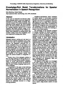
3.2 Change example Fig. 5 shows a sample workflow instance model, a sequence of model manipulation steps, and the resulting modified state of the model. On the left side, two snapshots of the workflow model are shown, with the differences (the delta) highlighted (the jPDL target model is omitted for clarity).
Change-Driven Model Transformations
7
tions in the same way as they will be used in the paper, along with explanations and examples. The textual concrete syntax featured in listings extends the the GT parts of the transformation language [11] of the Viatra2 framework.
Fig. 5 Example model change
The delta in-between could correspond e.g. to a GUI operation that inserts a new invocation between two neighbors in the control flow. If this workflow model had been transformed into a jPDL process before, the two models have to be re-synchronized after the change. The transformation has to react to this change, i.e. create a new JPDLNode that corresponds to Invocation i3, insert it into the sequence, and map the input and output parameters. 3.3 Constraints and Transformations with Graph Transformation While model transformations may be implemented in any generic programming language, specialized model transformation tools offer declarative, rule-based transformation languages to support the easy and concise definition and efficient execution of transformations. Several tools use Graph Transformation (GT) [8] as theoretical underpinnings. The approach of graph transformation captures models as (typed, attributed) graphs. Parts of the graph can be described by declarative queries called Graph Patterns (GP) [9, 10]. A pattern match is a conformant subgraph of the model; the match maps each pattern variable (nodes, edges) of the pattern to a concrete model element. The graph pattern matcher module is responsible for finding matches for patterns. A graph pattern may have a Negative Application Condition (NAC) to exclude certain cases. The model manipulation steps are defined by Graph Transformation Rules (GTR), using a GP called left-hand-side (LHS) to specify the condition when and where the rule is applicable, and another GP called right-hand-side (RHS) to declaratively indicate how the graph should be changed at the matches of the LHS (e.g. by specifying elements to be added, removed, or updated). For readers unfamiliar with the basic concepts of graph transformation, Appendix A provides the defini-
Example. Figure 6(a) shows a graph pattern that matches invocation nodes in the workflow model that have not been mapped to any jPDL nodes yet. This mapping information is preserved by traceability links, represented graphically by dashed lines. The rectangle marked by NEG encloses a subpattern defining a negative application condition; the two involved domains are highlighted for clarity. Figure 6(b) reveals a more complex pattern, that finds a transition edge connecting two such invocations in the workflow model, that have already been mapped to jPDL nodes, but the corresponding jPDL transition element does not exist yet. Taking a closer look at these patterns, we can identify the variables and pattern constraints of both the positive patterns and the NACs; they are summarized by the table in Figure 6. Listing 1 displays the same pattern as Figure 6(b). The bodies of patterns mainly consist of constraints expressed as predicates on variables. Entity constraints (e.g. type restrictions) are represented by unary predicates, while relation constraints (capturing the structural connectivity of the underlying graph model) are expressed by ternary predicates (edge variable, source, target). The name of the predicate is the node or edge type name, respectively; the list of variables affected by the constraint follows in parentheses. The pattern and its NAC subpatterns have a set of interface variables that are visible (exported) from outside.
4 A Language for Change-driven Rules 4.1 Requirements and motivation for change-driven rules For many transformation engineers, declarative, rulebased techniques may offer an easy-to-understand way to specify model transformations. Consequently, we propose such a high-level change-driven rule formalism where transformation rules are augmented with a guard. The guard is evaluated in context of the changes that the graph model has undergone to determine whether the rule is an appropriate reaction to the change. In rulebased expert systems, this idea of change as a distinguished representation of information has been used for decades; for instance, in the well-known terminology of Event-Condition-Action (ECA) systems [12], our guards correspond to the notions of ”triggering event” and the contextual condition of rules. As a complete adaptation of these techniques to model transformation technology (which is able to handle all relevant change processing
8
G´ abor Bergmann et al.
(a) Unmapped invocation
(b) Unmapped transition
Variables I1, N 1, I2, N 2, ItoN 1, ItoN 2, T r Constraints I:Invocation I1:Invocation I2:Invocation N 1:JPDLNode N 2:JPDLNode ItoN 1:traceability, I1 to N 1 ItoN 2:traceability, I2 to N 2 T r: transition, I1 to I2 NAC Variables I, N , ItoN N 1, N 2, JT , T o NAC Constraints N :JPDLNode JT :JPDLTransition ItoN :traceability, I to N JT in N 1 T o:JPDLTransition.to, JT to N 2 I
Fig. 6 Textual Representation of the Graph Pattern of Fig. 6(b) pattern noJPDLTr ( I1 , N1 , I2 , N2 ) = { Invocation ( I1 ); // entity c o n s t r a i n t traceability ( ItoN1 , I1 , N1 ); // r e l a t i o n c o n s t r a i n t JPDLNode ( N1 ); neg pattern connected ( N1 , N2 ) = { // NAC d e f i n i t i o n JPDLTransition ( JT ) in N1 ; JPDLTransition . to ( To , JT , N2 ); } JPDLNode ( N2 ); traceability ( ItoN2 , I2 , N2 ); Invocation ( I2 ); Invocation . transition ( Tr , I1 , I2 ); }
Listing 1 Example Graph Pattern
scenarios using a unified, high-level formalism) does not yet exist to our best knowledge, we believe that such a language – architected as an extension to an existing graph transformation language – will serve practical applications well, in a number of application scenarios (e.g. model synchronization [1], on-the-fly constraint validation [3] and model animation [13]). There are a number of requirements that such a language needs to fulfill: – reactivity to be able to specify dynamic model changes as events that activate a rule – conciseness to result in compact specifications for change-driven transformations – high-level specification to be able to abstract from irrelevant details – intuitiveness so that rules can be easily understood by those who are familiar with other model transformation languages – expressiveness in order to be able to specify a large class of change-driven transformations using this language.
Fig. 7 Simplified metamodel of the proposed transformation language
In this section, we define the concepts of changedriven transformations by proposing a language as an extension of the Viatra2 transformation language. A quick overview of the language concepts is presented in Fig. 7, which will be gradually discussed in the section: Section 4.2 defines change patterns, while Section 4.3 specify change driven transformation rules on the foundations of change patterns. Throughout the definitions, we heavily rely on some well-known concepts of Graph Transformation; for a more detailed introduction see Appendix A. These concepts include Graph Model G, Graph Pattern P , Graph Pattern with negative application conditions (NAC) P N = hP, N ∗ i, attributed Graph Models and Graph Patterns, and finally Graph Pattern matching, with G, m |= P meaning that m is a match for pattern P in graph G. Additionally, we also use the concept of Graph Transformation Rules consisting of a left-hand-side and a right-hand-side graph pattern (LHS and RHS), and the notion of applying the rule on a match of LHS, replacing it with an image of the RHS.
4.2 Change Patterns We define high-level guards for change-driven rules in the form of Change Patterns. In addition to conventional graph patterns matched against the post-state, guards should also contain constructs for expressing the difference between the pre-state and post-state in the form of change queries. An appearance query indicates a graph pattern with a new match in the post-state, while the disappearance query indicates that a match of a given graph pattern is invalidated by the change. An update query captures that an attribute changes from an old value to a new one, i.e. it detects if an old value of an attribute disappeared, or a new value appeared. The benefit of using graph patterns instead of elementary changes as appearance/disappearance queries is that a change pattern will match regardless of the order
Change-Driven Model Transformations
of elementary model manipulations that ultimately satisfied the appearance / disappearance / update queries. Thus it is irrelevant what the last operation was that e.g. completed the pattern of the appearance query. As a result, a single change pattern compactly captures a large set of different change sequences.
9
Here Gpre and Gpost represent the pre-state and poststate respectively, but their presence in the definition does not imply that the concept of change patterns is restricted to the snapshot scenario (see Section 2.1) – only to unify the semantic discussion.
Definition 1 (Change Pattern) Change Patterns ∗ (CP) can be defined as a tuple CP = hP N, P+∗ , P−∗ , U:= i, where – P N = hP, N ∗ i is the main graph pattern with positive pattern P and negative application conditions N ∗. – P+∗ is a set of graph patterns {Pi = hVi , Ci i} called appearance queries. Each appearance query Pi with variables (pattern elements) Vi and their constraints Ci represents that a certain graph pattern appears due to the change. Pi is allowed to share variables with P . – P−∗ is a set of graph patterns {Pj = hVj , Cj i} called disappearance queries. Each disappearance query Pj with variables (pattern elements) Vj and their constraints Cj represents that a certain graph pattern disappears due to the change. Pj is allowed to share variables with P . ∗ – U:= is a set of tuples {Uh = hvhM od , attrh , vhpre , vhpost i} called update queries. Each update query represents that a certain model element has one of its attributes changed, where vhM od ∈ V (P ) is a variable of P that represents the model element, attrh is the attribute name, and the (optional) variables vhpre , vhpost ∈ V (P ) represent the pre-state and post-state values of the attribute, respectively. – Appearance, disappearance and update queries altogether are called change queries. – The set of common variables of a change query and the main pattern is called its interface. T T Ii = Vi V (P ), Ij = Vj V (P ) and Ih = {vhM od , vhpre , vhpost }. S S – The pre-state pattern Ppre (CP ) = Pi ∈P ∗ Pi P − summarizes disappearance queries and the main positive pattern, i.e. all patterns representing existence in the pre-state. –S The post-state pattern Ppost (CP ) = S P summarizes appearance queries ∗ Pi Pi ∈P+ and the main positive pattern, i.e. all patterns representing existence in the post-state. The match of change patterns (Fig. 8) is defined against a pair of graphs Gpre and Gpost , such that Gpost is derived from Gpre by some (maybe only observable, but not controllable) model manipulation. Thus the sets of model entities (Entpre and Entpost ) and relations (Relpre and Relpost ) may intersect on elements that were preserved by the step from Gpre to Gpost . By definition, Dom (the immutable set of attribute values including all integer values, strings, etc.) is the same in both cases.
Fig. 8 Change Pattern concepts
All variables of the change pattern that represent attributes are required to be “bound”, in order to avoid unintended challenges such as equation solving. There are multiple ways to bind an attribute variable: either by declaring it as the attribute value of a model element, or by participating in the interface (header parameter) of a change query, or by being the result of a function (e.g. addition) on bound attribute variables. Similar restrictions hold for the graph patterns in NACs and change queries. Definition 2 (Match of Change Pattern) A match ∗ of the Change Pattern CP = hP N, P+∗ , P−∗ , U:= i in ∗ hGpre , Gpost i is the mapping m = hmP , m+ , m∗− i : CP → hGpre , Gpost i, where – mP : P N → Gpost is a match of P N , in the poststate Gpost : Gpost , mP |= P N . – For each Pi ∈ P+∗ , the set m∗+ contains a mapping mi : Pi → Gpost , such that – Gpost , mi |= Pi , i.e. mi a match of pattern Pi in graph Gpost , – mi (v) = mP (v) for interface variables v ∈ Ii , i.e. mi interfaces with the match of the main pattern, and – Gpre , mi 6 |=Pi , i.e. the same mi is not a match in the pre-state. – For each Pj ∈ P−∗ , the set m∗− contains a mapping mj : Pj → Gpre , such that – Gpre , mj |= Pj , i.e. mj a match of pattern Pj in graph Gpre , – mj (v) = mP (v) for interface variables v ∈ Ij , i.e. mj interfaces with the match of the main pattern, and – Gpost , mj 6 |=Pj , i.e. the same mj is not a match in the post-state. ∗ – For each Uh = hvhM od , attrh , vhpre , vhpost i ∈ U:= update query,
10
G´ abor Bergmann et al.
– Gpre |= mP (vhM od ).attrh = mP (vhpre ), i.e. the pre-state value of attribute attrh of vhM od was vhpre , and – Gpost |= mP (vhM od ).attrh = mP (vhpost ), i.e. the post-state value of attribute attrh of vhM od is vhpost , and – mP (vhpre ) 6= mP (vhpost ), i.e. there was a change between two different values, and – if vhpre or vhpost is omitted from the update query, its value is considered to be existentially quantified. For a match m = hmP , m∗+ , m∗− i : CP → hGpre , Gpost i, – the match is defined as mpre = S pre-state S m m , i.e. the unification of the match ∗ j P Pj ∈P− components corresponding to the pre-state pattern Ppre (CP ); consequently mpre is a match of the prestate pattern in Gpre , i.e. Gpre , mpre |= Ppre (CP ); –S the post-state match is defined as mpost = S mP , i.e. the unification of the match ∗ mi Pi ∈P+ components corresponding to the post-state pattern Ppost (CP ); consequently mpost is a match of the poststate pattern in Gpost , i.e. Gpost , mpost |= Ppost (CP ). Note that this definition is deliberately asymmetric for Gpre and Gpost , as the main pattern P N is interpreted on Gpost only. The same holds for P+∗ and P−∗ . It is also worth noticing that the language feature of update queries is a syntactic sugar. While it helps to concisely define change patterns in common cases and also potentially to increase CP matching efficiently, nevertheless appearance and disappearance queries alone provide enough expressive power. In particular, update query ∗ Uh = hvhM od , attrh , vhpre , vhpost i ∈ U:= is equivalent to the disappearance of the value assignment (for attribute name attrh ) between vhM od and vhpre , and the appearance of the assignment for the same attribute name between vhM od and vhpost . While not indicated before, the definitions for pre- and post-state patterns Ppre (CP ) and Ppost (CP ) are actually intended to take this representation of update queries into account. 4.2.1 Extensions Although not presented in the formal definition to provide better focus on the core contribution, there is a wide range of straightforward extensions to the presented version of the CP formalism (which is actually part of our language), including negative application conditions in the patterns used as change queries, nested NACs, change queries attached to a NAC of P N (or even a nested NAC) instead of P , etc. Without including a proof, it is worth pointing out that if these features are available, then the expressiveness of CPs becomes equivalent to first-order formulae over the set of predicates describing the pre-state and the post-state. This suggests that the CP formalism is powerful enough justifying the choice to be used to trigger changedriven rules. There are also some extensions which we
will use in later examples of the paper: for convenience, both graph patterns and CPs can be written as the composition of smaller patterns (even facilitating reuse) using the f ind keyword; this can be thought of dependencies between (change) patterns. 4.2.2 Example. Figures 9(a) and 9(b) show the CPs that detect deleted workflow transitions (in order to delete the jPDL transition), and newly created jPDL transitions (to be mapped back into the workflow domain), respectively. NACs are often visually represented as special sub-patterns (enclosed in a “NEG” box), the rectangles marked by appear or disappear indicate that the enclosed pattern is an appearance or disappearance query, respectively. As said earlier, the CP of Figure 9(b) is insensitive to the last operation that caused the jPDL transition to appear, it can be the creation of the transition, redirecting, moving under a different JPDLNode, etc. Listing 2 displays the same CP with a textual syntax. As an extension to the graph pattern language, change queries are available as a (sub)pattern definition with appear or disappear prefixes, also having a set of exported or visible variables (including the interface variables) listed in parentheses.
(a) Detecting deleted work- (b) Detecting created jPDL flow transition transition Fig. 9 Example Change Patterns change pattern newJPDLTr ( I1 , N1 , I2 , N2 , JT ) = { Invocation ( I1 ); traceability ( ItoN1 , I1 , N1 ); JPDLNode ( N1 ); appear pattern ( N1 , JT , N2 ) = { JPDL Transit ion ( JT ) in N1 ; JPDL Transit ion . to ( To , JT , N2 ); } JPDLNode ( N2 ); traceability ( ItoN2 , I2 , N2 ); Invocation ( I2 ); neg pattern ( I1 , I2 ) = { Invocation . transition ( Tr , I1 , I2 ); } }
Listing 2 Example Change Pattern
For demonstration purposes, these CPs are matched against the transaction depicted in Figure 5. The preand post-states are shown in Figures 10 and 11, respectively. The workflow model is indicated alongside its counterpart in the jPDL domain, but the traceability links and other details such as attributes are not shown. Traceability links are present between w0 and p0, i1 and
Change-Driven Model Transformations
n1, i2 and n2, di1a and pei1a, etc. We assume that the workflow model was changed (in Fig. 11), namely a new i3 invocation was created in the workflow, di3 input and do3 output specification were created within the invocation, a new t3 transition edge was created from the new invocation to i2, and the old transition t1 was retargeted to i3. The jPDL model, however, was not changed; transformation rules will have to detect the discrepancy and propagate the changes to the target model.
11
Fig. 12, the reaction is a controlled change transforming Gpost into an even newer state Gnew . The transformation substitutes the match of the guard (more precisely, the match of the post-state pattern Ppost (CP )) with the image of the RHS pattern, with the same semantics as a GT rule application. In fact, the application of the CDR will be defined by a reduction to an application of a GT rule.
Fig. 10 Pre-State of Example Transaction
Fig. 11 Post-State of Example Transaction
The CP in Figure 9(b) will not match against this change, as it contains an appearance query in the jPDL domain, but the jPDL target model was not changed. However, the CP in Figure 9(a), has a match. The current snapshot contains the two invocations and their corresponding JPDLNodes, but there was the t1 transition relation between i1 and i2 which is not present anymore (it was not actually deleted, just redirected). As the model manipulation did not change the jPDL part, the jPDL representation of this transition, namely jt1, is still present in the current model, so this is a match of the CP. More precisely, the disappearing variable T r in the change pattern will be substituted for transition edge t1, I1 in the pattern is mapped to i1 in the workflow, I2 is mapped to i2, N 1 to n1 in the jPDL domain, N 2 to n2, JT to jt1, T o to jt1t, finally ItoN 1 and ItoN 2 to the traceability links that are not shown. The occurrence of the CP will trigger the rule, that will be responsible for removing jt1. 4.3 Change-Driven Rules Using our Change Pattern formalism, we can now introduce change-driven transformation rules. GT-style rules consisting of a CP as a LHS/guard (instead of a conventional LHS pattern) and a graph pattern as RHS are Change-Driven Rules (CDR). A CDR specifies a reaction to the CP used as its guard. As explained on
Fig. 12 Change-driven rule concepts
Definition 3 (Change-driven Rule) Change-driven rules CDR = hCP, RHSi are specified by a guard ∗ change pattern CP = hP N, P+∗ , P−∗ , U:= i defining the applicability of the rule, and a postcondition (or righthand side) positive pattern RHS which declaratively specifies the result model after rule application. The poststate pattern Ppost (CP ) and RHS are allowed to share variables. Obviously, RHS may only use/delete elements that are not already deleted in the CP, hence the usage of the post-state pattern. Ppost and its match mpost in Gpost will also be used to define the application of the rule. CDR application is the replacement of the post-state pattern with the RHS, or equivalently, the application of a conventional GT rule obtained from the change-driven rule with Ppost substituted for LHS. Definition 4 (Elision of a Change-driven Rule) The elision of a Change-driven Rule CDR = hCP, RHSi is the Graph Transformation Rule RCDR = hPpost (CP ), RHSi, whose left-hand-side is the post-state pattern of the guard Change Pattern CP , and the righthand-side is shared with CDR. Definition 5 (Application of Change-driven Rule) A change-driven rule CDR = hCP, RHSi can be applied on a guard match m = hmP , m∗+ , m∗− i : CP →
12
G´ abor Bergmann et al.
hGpre , Gpost i after a change from pre-state Gpre to post-state Gpost . The application of the CDR results in a new graph model Gnew derived from Gpost , where the transition from Gpost to Gnew is identical to the application of the elision GT rule RCDR = hPpost (CP ), RHSi on post-state match mpost . If CP has no matches in hGpre , Gpost i, then CDR is not applicable. 4.3.1 Extensions While the declarative specification of GT rules and CDRs can be very concise in some cases (especially with pattern reuse through composition), in some cases it is more practical to also associate imperative actions to the rule that should be executed on the match of the guard. Examples include logging or debugging, chaining related rules, performing nontrivial computation, etc. Therefore the transformation language used in our examples contains an extension to the core CDR formalism, so that an action sequence can be attached to the rules using the action keyword. This technique provides a complete imperative alternative to using the declarative RHS formalism. Change-driven rules vs. GT rules. It is worth pointing out that both traditional GT rules and an earlier event-driven rule formalism (graph triggers in [3]) can be thought of as special cases of the more expressive CDR formalism. CDR rules reduce to GT rules in case there are no change queries, while CDR rules are equivalent to graph triggers in the case of an empty main pattern (graph triggers use the appearance/disappearance of the entire precondition pattern as guard condition). 4.3.2 Example Figure 13 and Listing 3 show the CDR that propagates transitions deleted in the workflow models to the jPDL domain. The guard CP, identical to Figure 9(a), activates whenever a transition disappears between two Invocations, which is still mapped to a transition element between the corresponding JPDLNodes. The RHS does not contain the JPDL transition element anymore, therefore it will be deleted when the rule is applied. For example, as already discussed, the CP guard will have a match on the pair of states depicted in Figures 10 and 11; the rule will be applied as a reaction, resulting in the deletion of the JPDL transition jt1 (and thus the connecting edge jt1t) that previously corresponded to the workflow transition. 4.4 Validation In the following, we summarize our arguments on why this transformation language extension answers the challenges of Section 2.2.1 and satisfies the requirements given in Section 4.1: – reactivity: using change patterns as guards for transformation rules, the transformation can react to changes in the model.
Fig. 13 Propagate deletion of Transition cdrule p r o p a g a t e De l W F T r ( I1 , N1 , I2 , N2 ) = { guard find delWFTr ( I1 , N1 , I2 , N2 , JT ); postcondition pattern noJT ( I1 , N1 , I2 , N2 , JT ) = { Invocation ( I1 ); traceability ( ItoN1 , I1 , N1 ); JPDLNode ( N1 ); Invocation ( I2 ); traceability ( ItoN2 , I2 , N2 ); JPDLNode ( N2 ); } }
Listing 3 Example Change Driven Rule
– conciseness: change queries capture the relevant information in the delta without the need for individually addressing possible sequences of elementary changes. – high-level specification: model changes can be abstractly captured as appearance and disappearance of graph pattern matches; and change-driven transformations are also independent from the source of the triggering changes. – intuitiveness: our language extends declarative static model queries and model manipulation (as provided by graph patterns and graph transformation rules) in a natural way by introducing change patterns (which are guards that specify elements which must appear or disappear) and change driven rules (which describe reaction to changes). – expressiveness: change patterns allows the transformation designer to specify rules which can distinguish between identical post-states of the model based on the modification trajectories which led to that state, without (i) having to encode these modifications into complex traceability models and (ii) bloating transformation rules with them. In other words, change-driven rules extend the expressive power of graph transformation rules by high-level queries corresponding to the changes exhibited by the graph.
5 Implementation Architecture The following sections outline a system architecture that implements change-driven transformation. Solutions to the following task items are required:
Change-Driven Model Transformations
– (positive and negative) graph pattern matching of the CP’s main pattern in the post-state – evaluating and matching appearance and disappearance queries – evaluating update queries – matching change patterns, using the solutions of the above three tasks – applying change driven rules on matches of the guard change pattern The first three of these tasks require different implementation techniques in different change scenarios (see Section 2.1), to take advantage of the benefits and avoid unnecessary operations that may degrade performance. First, Section 5.1 discusses our proposed solutions to the first three tasks in all change scenarios except for the live case. Next, Section 5.2 focuses on the live scenario with its unique execution model. Finally, the last two task items are addressed in Section 5.3. 5.1 Change query evaluation in documented or invisible change scenarios Documented history and command scenarios In the documented change scenarios, either the pre-state or the post-state of the model is available along with a delta document recording the changes. In order to match appearance and disappearance queries, existing graph pattern matcher algorithms have to be slightly modified to operate on a graph that contains the elements of the available snapshot and also the elements that only occur in the delta document. This graph should distinguish unchanged, deleted and created elements. A match of a positive graph pattern is only considered valid in the post-state, iff it contains no deleted elements. A pattern with NACs has a valid match in the post-state iff it is a valid post-state match of the positive pattern, and all NAC matches (if any) are disappearing (see later). A pattern match is considered appearing iff it is valid in the post-state (as defined above), and contains at least one created element, or has at least one NAC match (which is – as stated above - disappearing). Finally, a pattern match is considered disappearing if it contains no created elements, all of its NAC matches (if any) are appearing, and there is either at least one deleted element of the positive match, or a NAC match (which must be appearing). Using these rules, the pattern matcher can determine the match set of the main pattern in the poststate, as well as that of the appearance and disappearance queries. Attribute updates are straightforward to be evaluated based on the delta document. Snapshot scenario In the snapshot scenario, both the pre-state and the post-state are directly available, therefore change query evaluation is reduced to fairly simple steps. An appearance query is satisfied if the pattern is
13
matched in the post-state, but the same match is invalid in the pre-state; and vice versa for disappearance queries. Therefore evaluating these queries require a tailored graph pattern matcher that is similar to algorithms dealing with negative patterns. Finally, whether and how a certain attribute was updated can be detected using referenced value comparison. However, one of our assumptions here was that if a model element exists in both states, it is trivial to recognize that they are in fact the same element (this is actually required in the definition of Change Pattern). This is possible if model elements have a unique identifier that is preserved across different versions. Unfortunately, in some modeling environments this is not guaranteed; for example, generic EMF objects are not identifiable by default in a way that is valid across snapshots (but fortunately EMF provides both live notifications and redo stacks instead). In this case, the two versions of the model have to be reconciled against each other (by either a generic heuristic or a domain-specific way) before the changes can be computed and CDR can be applied; see the related literature on model comparison [14]. Invisible scenario As only the post-state is available, post-state matching of the main pattern is trivial in this case, but evaluating change queries is not. The common solution to this problem has significant time and space overhead: the transformation creates a shadow copy of the model each time it is invoked. On the next transformation run, the model itself represents the post-state, but the shadow copy preserves the pre-state, therefore the change queries can be evaluated. Of course, there is no need to replicate the entire model; it is sufficient to store the match sets of patterns used as appearance and disappearance queries, and to preserve the attribute values corresponding to element types and attribute names involved in update queries. The appearance and disappearance queries can be evaluated by matching the patterns against the post-state and comparing the match set against the one preserved in the shadow copy. Likewise, update queries can be evaluated by comparing the current attribute value against its shadow copy. To prevent inconsistencies, the shadow copy should be inaccessible to normal model editing operations, which can be achieved either storing it separately (e.g. in a different file), or by using special model element types, markers, etc., that visual editors and other transformations ignore. If it is stored separately, the problem of preserving model element identity has to be dealt with, similarly to the snapshot scenario. A widespread practice [15, 16] is to use the traceability model (sometimes called reference model or correspondence model) in a way that it preserves the LHS (or a significant subset thereof) of all executed rules. Thus the traceability connections essentially store a copy of the source model, thereby providing a shadow copy
14
functionality. In those model transformation approaches where this is not handled automatically, significant manual effort is required for maintaining this shadow copy. With change-driven transformations, however, the platform can provide change queries as a service, hiding implementation details. The hidden implementation will involve an automatic shadow copy mechanism in the invisible change scenario (and less resource intensive solutions in the other change scenarios). This allows a much simpler maintenance of traceability in many cases (especially bidirectional synchronization), sometimes as simple as using the same name for a source and target element, as there is no need to manually preserve the entire LHS.
5.2 Change query evaluation in live change scenarios Challenge of live scenarios While all techniques for the documented scenarios are functionally correct in the live scenario as well, there may be an additional important requirement in this case. Live notifications can be used to perform live transformation, where change-driven rules can be executed on-the-fly. Since live notification is received about changes that are in progress, and reactions are triggered during an interactive session, pattern matching is required to be responsive and efficient. We propose an architecture capable of efficiently matching change patterns and applying change-driven rules with live monitoring of the model as it evolves. The entire architecture is illustrated in Fig. 14. The rest of Section 5.2 discusses how change queries are evaluated efficiently in live scenarios.
Fig. 14 Implementation architecture for change-driven rules in the live scenario
Incremental Pattern Matching The aim to execute transformations without the costly re-evaluation of unchanged parts of the evolving (source) model is called source incrementality. Source incrementality can be achieved by employing incremental pattern matching
G´ abor Bergmann et al.
techniques; for example, the RETE algorithm [17] was used in [18]. The key idea of incremental pattern matching is that matches of a pattern are cached to be readily available at any time, and this cache is incrementally updated whenever notifications are received about changes in the underlying model. Obviously, such a technique results in increased memory consumption in order to store match sets. Furthermore, these stored result sets have to be continuously maintained whenever the model is changed, causing an overhead on model manipulation. Nevertheless, benchmarks [19] indicate that incremental pattern matching can improve performance or scalability by several orders of magnitude in certain scenarios. Moreover, incremental pattern matching leads to easy discovery of appearing or disappearing pattern matches, thus it can be used to efficiently implement the change query feature of change patterns by incremental calculation of matching set differences. Having received change notifications, the incremental pattern matcher shows an up-to-date picture of the post-state. This is true even in the command scenario where these changes might not have been applied to the model itself, still retaining the pre-state. Therefore the post-state graph pattern matching of the main pattern can be performed by the incremental pattern matcher in both history and command scenarios. In the history scenario, the model itself reflects the post-state, therefore a regular (local search) pattern matcher is also applicable for this task, if it is preferrable for performance reasons. Delta Monitoring A delta monitor is a component that can be attached to a match set cache of the incremental pattern matcher at any time, and it will start to record changes affecting the match set from that time on. At any point in the future, the delta monitor will be able to report about which new matches appeared and which matches disappeared since it was initialized. This is efficiently achieved by hooking into the internal notification/update mechanism of the incremental pattern matcher. Changes of a single match (e.g. the same match appearing and then disappearing later) may invalidate each other, therefore the delta monitor really reflects (a projection of) the delta between the two states, and not just recorded history. A slightly modified delta monitor can be used to remember attribute updates. Change query evaluation Change queries can be efficiently evaluated using delta monitors and incremental pattern matching. Before the change is performed (or notifications are received), a delta monitor is to be attached (or reinitialized, if already attached) onto the incrementally maintained match set of each graph pattern that occurs as a change query within a CP. After the change, the contents of the delta monitors will reflect the graph pattern matches that have appeared or disappeared. This complements the post-state reflected by the
Change-Driven Model Transformations
incremental pattern matcher (or alternatively, in the history scenario, the model itself), to provide all necessary information for matching change patterns.
5.3 Implementing Change-Driven Rules
Matching Change Patterns Change patterns are equivalent to an extended graph pattern formalism, where the set of admissible pattern constraints contains change sets of pattern matches as hyperedge constraints [20]. In the end, the match set of a change pattern can be determined from the match set of the change queries, the main positive pattern and the negative patterns; and such a pattern matcher architecture is conceptually similar to existing ones dealing with negative application conditions. Therefore graph pattern matching mechanisms can be used to evaluate change patterns, based on the partial solutions (change queries and post-state pattern matching of the main pattern) obtained differently in each change scenario.
Rule execution The sequence of elementary model manipulation operations executed by any transformation unit, GUI-based manipulation, model merge or other job can be arbitrarily segmented into transactions, that are assumed to result in a consistent state of the affected model. The transaction is the unit of change that CDRs will react to; the starting and the end points of the transaction will be considered the pre-state and the post-state, respectively. In documented change scenarios, the whole change process between the given preand post-states can be considered a single transaction. In live scenarios, as notifications may be continuously sent, it is a nontrivial question how to segment transactions; it helps if there is some support for explicitly defining transaction boundaries and commit points. A typical transaction can be e.g. the execution of single functionality through the UI, corresponding to multiple elementary operations. Upon the end of each transaction, the change patterns are evaluated to determine which change-driven rules are applicable. If there are any such CDRs, they are applied on the model, using algorithms that are identical to regular GT rule application. As this rule application phase modifies the model, it can be considered a change transaction itself, with its effects wrapped into a separate transaction. At the end of this second transaction, the effects of executed CDRs can be reacted to as well, as long as there are triggered CDRs. This follow-up loop is actually a live scenario, regardless of the circumstances of the original triggering change. This queue-based execution schema has been previously elaborated in details in [3].
15
6 Elaboration of the case study 6.1 Overview of the approach In this section, we demonstrate the concept and the application of change-driven transformations (Sec. 2), relying on the novel change-driven transformation formalism of Sec. 4, by the elaboration of the motivating scenario described in Section 3. 6.1.1 Challenges In the current paper, we investigate a model synchronization scenario where the goal is to asynchronously propagate changes in the source model MA to the target model MB (Fig. 15). This means that changes in the source model are not mapped on-the-fly to the target model, but the synchronization may take place at any later time. However, it is important to point out that the synchronization is still incremental, i.e. the target model is not re-generated from scratch, but updated according to the changes in the source model.
Fig. 15 Model synchronization driven by change models
Moreover, our scenario also requires that MB is not materialized in the model transformation framework, but accessed and manipulated directly through an external interface IF of its native environment. This is a significant difference to traditional model transformation environments, where the system relies on model import and export facilities to connect to modeling and model processing tools in the toolchain. Here, we only assume the existence of very simple (untyped) traceability links. These links need not be actual persisted references; it is sufficient to establish “virtual” connections defined by using the same ID or name for the two elements in the two models. Moreover, we will also discuss various operations for processing change models: – Processing live historical changes. Based upon the notification mechanism of the underlying model management framework, we can process changes onthe-fly as they are generated by the user or a model transformation. In our case study example (see Section 6.3), these changes (of the source model) will be used in a model synchronization scenario to produce change commands (that can be applied to the target model).
16
– Processing documented command changes. Change commands represented as models themselves can be automatically applied to models. More precisely, one can combine the current snapshot of the target model M (representing the initial state) and a change model CM to create the final snapshot M 0 . An example for applying a change model will be presented in Section 6.4. 6.1.2 Technology As the source model MA is in the model space of the transformation engine, model changes are directly observable through a notification mechanism. These changes are processed by change-driven rules (changeA in Fig. 15). However, as the target model MB can only be manipulated asynchronously, we design the transformation in a way that instead of direct target model manipulations, we encode the changes of the target models as change command model instances CMB . These models conform to a change command metamodel (presented in Fig. 16 of Sec. 6.2), and represent parameterized model manipulation operations. Hence, the actual model transformation itself is implemented as a mapping between the (in-memory) changes of the source language A to change models corresponding to change commands that can be applied in language B (see middle part of Fig. 15). This transformation is described later in details in Sec. 6.3. As change command models represent a trace of model evolution, they may be automatically applied to models (see right part of Fig. 15). More precisely, such a transformation combines a snapshot of the model MB (representing the initial state) and a change command model CMB (representing a sequence of operations applicable starting from the initial state) to create the final snapshot MB0 . In other words, the change command model CMB represents an “operational difference” between MB0 and MB , with the order of operations preserved as they were actually performed on MB . As change-driven transformations can transparently process both observable and persisted changes (Sec. 2), we use our rules to map change command models into native function calls that directly manipulate the external target model (Sec. 6.4).
6.2 Change models First, we briefly overview how to persist changes as change models. For this elaboration, we only concern observable (and non-controllable) changes (the representation of controllable changes - e.g. as graph transformation rules - has been discussed extensively in literature [21,22]). To clarify and capture the notions of domain-specific model changes precisely, we present a simplified clas-
G´ abor Bergmann et al.
sification system for jPDL model changes based on a metamodel (Fig. 16).
Fig. 16 Change command metamodel for jPDL
By the terminology of Section 2.1, both historical and command -type changes represent a difference (delta) between a pre-state and a post-state of the model. They differ only in their interpretation: histories are valid with respect to a post-state, while commands may be applied to a pre-state. Hence, in our model-based taxonomy, both notions are represented by the jPDLCommand type. The next relation enables the representation of operation sequences (transactions). Change commands contain ordered elementary change operations. This metamodel uses unique IDs to refer to (nonmaterialized) model elements (as defined in the jPDL standard); since jPDL documents also follow a strict containment hierarchy, creation operations (as depicted in Fig. 16) refer to a parentID in which an element is to be created. In the follow-up examples of our case study, we will make use of CreateJPDLNode and CreateJPDLAttribute to illustrate the usage of this domain-specific change history metamodel.
6.3 Propagating changes by change-driven transformations In this section, we describe a sample transformation rule where the creation of an Invocation in the domainspecific workflow language is mapped to the creation of a corresponding jPDL Node and its attribute (Fig. 17). This is a practical elaboration of the ”live historical” scenario described in Section 2.1. We use a change-driven graph transformation rule, which defines a guard condition that triggers when a new Invocation node is added to the domain-specific workflow model. The guard consists of a context definition (the common pattern referring to the already existing Workflow node) and the change pattern (referring to the newly created Invocation node). In the postcondition part, the corresponding jPDL-specific change command model elements, along with the traceability model
Change-Driven Model Transformations
transformation mapInvocation () = { /* This is a common static part of the pattern , * matched for all change p a t t e r n s * and p o s t c o n d i t i o n s . */ common pattern ()= { Workflow ( WF ); } /* This cdrule p r o c e s s e s the c r e a t i o n of * an i n v o c a t i o n node */ cdrule newInvocation () = { guard appear pattern ( I ) = { Invocation ( I ); Workflow . nodes (_ , WF , I ); } postcondition pattern ()={ /* create a JPDL Node and its c o r r e s p o n d i n g * a t t r i b u t e node in the JPDL - DOM */ CreateJPDLNode ( JN ) { nodeID -> I . ID ; parentID -> WF . ID ; } C r e a t e JP D L A t t r i b u t e ( JA ) { nodeID -> I . ID + " . function " ; parentID -> I . ID ; targetValue -> I . functionName ; } jPDLCommand . next (_ , JN , JA ); // t r a c e a b i l i t y models // one for c o n n e c t i n g the i n v o c a t i o n node I1 // to the JPDL node TraceRef . External { sourceIDs -> [ I . ID ]; targetIDs -> [ JN . ID ]; } // and one to its a t t r i b u t e TraceRef . External { sourceIDs -> [ I . ID ]; targetIDs -> [ JA . ID ]; }}}
Fig. 17 Example change-driven transformation rule
are declared. As Invocations are represented by jPDL Nodes with an attribute node, the target change model will consist of two “create”-type elements, chained together by the jPDLCommand.next relation. The simple traceability model consists of two mapping nodes that connect the Invocation node to its counterparts in the target model (the JPDLNode and the JPDLAttribute). In this example, we make use of the fact that both source and target models have a strict containment hierarchy (all elements have parents), which is used to map corresponding elements to each other:
– Based on the new node I in the source model, we calculate the target parent’s ID parentID as WF.ID. – Similarly, the target jPDL node’s ID is I.ID
17
– The jPDL Attribute node’s ID will be calculated as ’I.ID’.function to place the target node under the target parent. – Finally, the attribute functionName designates a particular function on a remote interface which is invoked when the workflow engine interprets an Invocation workflow node. It is represented by a separate node in the jPDL XML-DOM tree. The targetValue attribute of the additional CreateJPDLAttribute element is derived from the appropriate attribute value of Invocation node in source model.
Fig. 18 Example execution sequence
Sample execution sequence Fig. 18 shows an example execution sequence of this rule. The sequence starts with a model consisting only of a top-level container node w0 of type Workflow. In Step 1, the user creates a new Invocation node i0 inside w0. The change-driven transformation engine triggers the execution of mapInvocation() only if the subgraph w0 – i0 is complete. In Step 2, mapInvocation() is fired, and the appropriate jPDL change command model instances are created. 6.3.1 Handling attribute changes Updates to attribute values in the source model can be easily processed by change-driven transformation rules. Fig. 19 illustrates a case where the functionName attribute of Invocation nodes is being observed; this rule maps a change in the attribute value to a Change Command that can later be executed on the target model that will update the jPDLDOM attribute value accordingly. The target node in the jPDL model (jP DL ID) is identified by using the (external) traceability model element referenced in the common pattern of the rule.
18
/* This cdrule handles the change * of the function ’ s name */ cdrule c h an g eF un c ti o n N a m e () = { common pattern ( I1 , jPDL_ID ) = { TraceRef . External { sourceIDs -> [ I1 . ID ]; targetIDs -> [ jPDL_ID ]; } guard change pattern () = { Invocation ( I1 ); update I1 . functionName from _OldName to NewName ; } postcondition pattern ()={ setAttribute { nodeID -> jPDL_ID . function ; attributeName -> ’ targetValue ’; attributeValue -> NewName ; }}}
Fig. 19 Attribute update processing by CDTs
Note that for bidirectional synchronization with attributes, traditional GT-based formalisms would require storing the attribute value in the traceability model in order to be able to detrmine the direction of change.
6.3.2 Mapping complex operations Certain (simple) changes of the source model may require to be mapped to complex operations on the target model. This is typically the case when the mapping between source and target languages is not a one-to-one correspondence, but a more complex abstraction. All such complex operations can be performed even when using change commands instead of direct model manipulation, as the example in Fig.20 illustrates. In Fig. 20, the change-driven rule mapDeleteInvocation() is shown. This rule triggers if a previously mapped Invocation node is deleted (indicated by the combination of the TraceRef.External model element and a change pattern that triggers when an Invocation disappears from the graph). Upon the registration of this event, this rule will formulate the following commands to be performed on the target model: 1. First, the corresponding jPDL node will be located and marked as deleted (by setting the isDeleted attribute to true with a setAttribute-type jPDLCommand). Next, a new JPDLWaitState will be created to replace the deleted JPDLNode. 2. Finally, a more complex modification sequence is defined that disconnects the JPDLNode from the jPDL process graph, by overwriting the ”transition” references of all its preceding nodes to point to the newly created WaitState. Note that the newly created jPDLCommand elements are connected sequentially by using the PreviousCommand helper variable through the forAll cycle in Fig. 20.
G´ abor Bergmann et al.
/* This cdrule handles d e l e t i o n of an * i n v o c a t i o n node in a complex way . */ cdrule m a p D e l e t e I n v o c a t i o n () = { common pattern () = { Workflow ( WF ); } guard change pattern j p d l N o d e O r p h a n e d ( JPDL_ID ) = { disappear pattern invo cationN ode ( I2 ) = { Workflow . nodes (_ , WF , I2 ); Invocation ( I2 ); } TraceRef . External { sourceIDs -> [ I2 . ID ]; targetIDs -> [ JPDL_ID ]; } } postcondition pattern ()={ /* do not delete c o r r e s p o n d i n g JPDL node ( if e xistent ) * but first (1) mark it as deleted * and second (2) remove it from the process graph * by r e p l a c i n g it with a wait state */ setAttribute ( SA ) { nodeID -> JPDL_ID ; attributeName -> ’ isDeleted ’; attr ibuteVal ue -> ’ true ’; } C r e a t e J P D L W a i t S t a t e ( CJWS ) { nodeID -> JDPL_ID ; parentID -> WF . ID ; } jPDLCommand . next ( _SA , CJWS ); } action { // connect all p r e c e d i n g nodes to the wait state let P re vi o us Co m ma nd = undef in forall PN with find precedingNode ( PN , I2 ) do seq { new setReference ( SR ) { nodeID -> PN . ID ; referenceID -> ’ transition ’; refe renceVal ue -> CJWS . nodeID ; } new jPDLCommand . next (_ , previousCommand , SR ); update p re v io us C om ma nd = SR ; } }}}}
Fig. 20 Mapping changes to complex operations
6.4 Applying change models to non-materialized models In this section, we elaborate a technique of processing ”documented historical” changes (in the terminology of Section 2.1). On the macro level, change models are represented as chains of parametrized elementary model manipulation operations. As such, they can be processed linearly, proceeding along the chain until the final element is reached (thus modeling the execution of a transaction). The consumption of a change model element is an interpretable step with corresponding actions performed in the context defined by the change model’s references. As Fig. 15 shows, we apply change models to manipulate non-materialized models through an interface. The speciality of this scenario is that instead of working on directly accessible in-memory models, the transformation engine calls interface functions which only allow basic queries (based on ids) and elementary manipulation operations. In this case, change models are very useful since they allow incremental updates, as they encode directly applicable operation sequences.
Change-Driven Model Transformations
19
In order to apply change commands to external models, the transformation engine is augmented with a ”native model access interface” component. This interface allows for query and manipulation operations as follows: for the jPDL models of the motivating scenario, we mapped the XML-DOM process model manipulation programming interface to Viatra2’s native function API. The following native functions are used: – getElementById(ID): retrieves a jPDL element identified by its unique ID. – createElement(parentRef,targetID): creates a new jPDL DOM element as a child of its parent (identified by parentRef ), with a given unique ID (targetID). – addElement(DocID,elementRef ): adds the element elementRef to the jPDL DOM identified by DocID. – addElementToParent(parentRef,elementRef ): adds the element elementRef to the jPDL DOM’s node identified by parentRef. – setContents(elementRef,text): sets the textual content of the given DOM element (elementRef ) to text. In this scenario, the mapping rules and the simple traceability implementation (direct id mapping) allow for the changes to be mapped and applied in a straightforward way, without complex navigation and queries on the target model.
Example transformation rule In this case study example, we define a change-driven application rule based on domain-specific change commands for the jPDL XML-DOM model (Fig. 16). Fig. 21 shows the newCompoundJPDLNode() rule, which is used to interpret a subsequence of change model chains for the jPDL domain. More precisely, this rule’s guard matches for a condition that describes that a new jPDL node, along with its ”function” attribute is to be created. In the change command model representation, this corresponds to the pair of CreateJPDLNode and CreateJPDLAttribute change model fragments. The rule uses native functions createElement, addElement to instantiate new jPDL XML elements directly in the deployed process model on the workflow server; and setContent is used to overwrite the attribute node’s textual content. The upper part of Fig. 21 shows the final three steps of our running example. In Step 3, the initial state of the deployed workflow model, the process definition corresponding to Workflow w0 is still empty. During the rule execution, first, the jPDL Node i0 is created (Step 4), and then in Step 5, the attribute node is added with the appropriate textual content. The entire algorithm which applies change models follows the linear sequence of operations along the relations with type jPDLCommand.next; the first operation in a transaction can be determined by looking for a change model fragment without an incoming jPDLCommand.next edge.
/* * This CD rule maps JPDL nodes to the * e x t e r n a l JPDL - DOM tree . */ tran sformat ion mapNode () = { /* * This cdrule handles the case when a new JPDL node * is added t o g e t h e r with its " f u n c t i o n " a t t r i b u t e . * This is checked by giving an a t t r i b u t e c o n d i t i o n * on the ID suffix . */ cdrule newNode () = { guard change pattern () = { appear pattern () = { JPDLNode ( JN ) { JPDLAttribute ( JA ); check ( JA . nodeID == JN . nodeID + " . function " ); } } } action { // create JPDL Node - Step 4 // we m a n i p u l a t e e x t e r n a l models here call DOM . addElement ( JPDLRoot , DOM . createElement ( JN . parentID , JN . nodeID )); // create JPDL A t t r i b u t e - Step 5 let DOM_ANode = DOM . createElement ( JN . nodeID , JA . nodeID ); DOM . setContent ( DOM_ANode , JA . value ); call DOM . a d d E l e m e n t T o P a r e n t ( JN . nodeID , DOM_ANode ); }}}
Fig. 21 Applying change models through the jPDL XMLDOM API
7 Case study on evolutionary constraints A second motivating scenario is from the domain of security requirement engineering, using the Air Traffic Management case study of the SecureChange European FP7 project. A requirement model assists security engineers to capture security-related aspects of the system, to analyze the security needs of the stakeholders, and to argue about potential security threats. The concepts of a security requirement modeling language such as SecureTropos [23] typically include actors and their goals, security-critical information assets and other resources, actions to fulfill goals, trust relationships, delegation of responsibility over assets, goals or actions, etc. An important role of security requirement models is to support reasoning about security properties by formal [24] or in-
20
formal [25] argumentation techniques in an early stage of development. These arguments may support or refute the satisfaction of security requirements, and are built upon assumptions and ground facts. Some of these facts originate from the security model, and are called evidence. 7.1 Metamodel for security requirements To introduce this case study, we use a simplified security metamodel shown in Fig. 22. The model contains Arguments, that record a formal or informal reasoning process conducted in the past. An Argument is linked to requirement model elements that support it as evidence. The requirement model presented here is a simplified actor model based loosely on i* [26]. An Actor is a stakeholder or an autonomous part of the system. Task s are performed by Actors to support fulfilling requirements. Actors can provide Resources that are valuable data assets. Communication elements represent that a sender Actor makes some data assets available to a receiver Actor. Several important element types such as Goal s or Trust are missing, as they are not relevant to the example scenario; Communication here replaces a more general class of Delegation relationships for the sake of simplicity; attributes are also omitted.
G´ abor Bergmann et al.
– T1 “Use data security and secure communication technologies”, to make sure the Air Traffic Controller is in control of RAS. – T2 “Conduct a yearly IT security training of the whole staff”, to reduce the likelihood of social engineering attacks. – T3 “Enforce policy that every manual decision has to be approved by a second member of the controller staff”, to reduce the impact of human error or malice. – T4 “Perform a quarterly security screening of employees”, monitoring whether an employee has big debts, or can be blackmailed into helping criminals, or has befriended terrorists, etc. to reduce the likelihood of malice. To decide whether the integrity of RAS will be maintained, security experts conduct an informal argumentation analysis ARG. Based on the model and their background knowledge, they judge that they are confident in this security requirement. Tasks T1−4 and Resource RAS are used in their argument, so they are recorded in the model as the evidences for ARG.
Fig. 23 An example security model and two evolutions
7.3 Example evolutions Fig. 22 The security metamodel used in the example
7.2 Sample model Fig. 23 shows a security model for air traffic communication systems. The three actors are Air Traffic Controller (AT CO), Airlines (AL) and Catering Services (CS). Actor AT CO provides resource RAS (runway assignment), and communicates it to AL. Actor AL provides resource M O (meal orders), and communicates it to CS. The integrity of data asset RAS is security-critical, because if terrorists were able to change RAS, they could make planes crash. To ensure the integrity of RAS, AT CO carries out the following Tasks:
An evolution triggering re-evaluation A possible evolution of the model is the following: to cut back costs, AT CO plans to reduce the frequency of security screenings, so T4 will be modified to ”Perform a yearly security screening of employees”. Thus change is inflicted on an evidence for ARG. Since we have no formal way to determine whether the modified Task can fulfill the security needs, the argumentation experts are alerted to revisit argument ARG. They decide e.g. that the security requirement is still met with the weakened guarantees, based on regulation, previous experience and a risk analysis conducted by Risk Engineers. An evolution not requiring re-evaluation Another possible evolution is that the communication between AL and CS is now routed through a new Actor SW IM (SystemWide Information Management). This change can have
Change-Driven Model Transformations
a wide influence on the system, but it does not invalidate the argument ARG, as no evidence of ARG was involved in the change. Therefore this time there is no need for the argumentation experts to exert further manual effort. 7.4 Evolutionary constraints Security requirement models have their set of wellformedness constraints, ensuring that the model is meaningful and consistent. We discussed graph pattern-based on-the-fly validation of well-formedness constraints in a preceding work [3]. These constraints are static in the sense that they only restrict the current state of the model. However, there are cases where evolutionary constraints are needed, that can take into account the change that is applied to the model. In the example evolution outlined in Section 7.3, invalidating informal arguments was such a problem. Formal and informal argumentation is carried out using the requirement model, to determine which security requirements are met. This argumentation is a laborious and costly process requiring significant human expertise. In evolving security-critical applications, it is important that the argumentation is only carried out for those security requirements that are influenced by the change of the model. Thanks to the traceability from Argument to evidence, there is enough information to determine which arguments need to be re-evaluated. The argument has to be invalidated if one of its evidences is involved in a change. This, however, cannot directly be determined by using only the present (post-state) of the security model. The challenge is to provide a straightforward and efficiently evaluated declarative language for this purpose. We propose on-the-fly, incremental evaluation for a wide range of evolutionary constraints that can be implemented as an efficient reactive mechanism by using Change Patterns and Change-Driven Rules. 7.5 Change-Driven Transformation for Evolutionary Constraints We propose establishing a set of CDRs that would flag invalidated arguments as invalid and request argumentation analysis. The key difference between each of these rules is the guard Change Pattern. The recommended strategy is to identify types of changes that warrant a re-evaluation of the argument, and define a rule for each of them. To aid in building CPs and CDRs, some helper Graph Patterns are defined first. Graph Pattern validArgument(A) captures an Argument A that has not been invalidated, while GP evidenceOf Argument(A, E) captures an argument A and a model element E which it references as an evidence.
21
The CDR invalidateU ponEvidenceU pdate() is activated when an attribute of an evidence element is updated. The rule is guarded by a CP that contains an update query linked to a match of evidenceOf Argument(A, E) and validArgument(A). The following code sample shows an initial version of this rule in a simplified syntax: change pattern e v id en ce U pd at e d (A , E ) { // static c o n d i t i o n find validArgument ( A ); find e v i d e n c e O f A r g u m e n t (A , E ); // event : element updated ! // attr . name and values are ignored update E . _ from _ to _ ; } cdrule i n v a l i d a t e U p o n E v i d e n c e U p d a t e (A , E ) { guard ev id e nc eD el e te d (A ,F , M ); action { call f la g_ as _ in va li d ( A ); } }
As an example for the application of this CDR, suppose that the evolution described in Section 7.3 is carried out. This means that Argument ARG is a match of validArgument(A); at the same time, ARG and T4 (“Perform a quarterly security screening of employees”) constitute a match of evidenceOf Argument(A, E). Whenever an evolution updates an attribute of this Task (e.g. downscale to yearly screening to cut costs, as in the example), the update query will detect this, making (ARG, T4 ) a match of the change pattern evidenceU pdated(A, E) and activating the CDR. The rule will flag the argument ARG for re-evaluation; argumentation experts will be alerted to revisit the argumentation and decide whether the looser policy is enough to maintain security needs. Similarly, a second CP could capture arguments whose evidence is deleted. Due to the flexibility of the CP formalism, additional similar rules can be created depending on system-specific policies; for instance the argument should be invalidated if a model element is of a certain type, and edges of certain types are connected to (or disconnected from) it.
8 Discussion Now we discuss the potential advantages and limitations of change-driven transformation over traditional model transformation techniques.
8.1 Theoretical discussion In this theoretical discussion, we primarily focus on graph transformation based approaches, which provide the closest correspondence to our techniques, moreover, they have a sound, well-established underlying theory. Theoretical expressiveness of change driven transformations While not formally proven in the current paper
22
for space considerations, it is worth pointing out that for each change-driven transformation system (CDTS) a corresponding graph transformation system (GTS) can be derived, which simulates the CDTS. As a result, our CDT formalism is not more expressive in a pure theoretical point of view, but it is still Turing complete. The construction essentially builds upon storing explicitly the pre-state as a dedicated part of the model. Then a separate set of GT rules would be responsible for (1) the detection of change and management of prestates and post-states (based on the difference between Gpre and Gpost ) and (2) simulating the effect of a CDTS (based on the difference between Gpost and RHS). As a consequence, both the underlying model and the rule set would explode. Without this special encoding, the GT rules are less expressive as they take only the post-state into account to determine which action to take while CD rules can refer to the pre-state as well. As a side remark, a CDTS can be constructed even if the model transformation problem itself is nondeterministic by its nature, thus it is not a function but a relation between the source and target language (e.g. a tree-based priority model needs to be flattened to an arbitrary sequence respecting priority relations).
Analysis of change-driven transformations The main practical relevance of this simulation property from CDTS and GTS is that it enables to investigate traditional semantic properties like termination or determinism using the rich theory and proof techniques (e.g [27, 28]) of graph transformation systems. For instance, if the simulating GTS can be proven to be terminating, then the original CDTS is terminating as well; while GTS termination is undecidable in general, there are established proof techniques for concrete systems. As a consequence, we believe that many existing analysis techniques of GTS are reusable for CDTSs. Exploring this idea in detail is left as future work.
Constraint detection by change-driven transformations Declarative specifications (like graph patterns, graph transformation rules, OCL constraints) are frequently used for detecting the violation of well-formedness constraints in domain-specific models. However, constraints related to the temporal behavior or the evolution of models are very hard to specify and detect as it requires to explicitly encode the sequence of model snapshots as part of the model, and thus also part of the constraint. Change patterns provide a direct and succinct way to detect a class of constraints related to the trajectory of model evolution (see the case study of Sec.7).
G´ abor Bergmann et al.
8.2 Expressiveness wrt. model synchronization languages As CDT rules are unidirectional, CDT specifications can be more complex than that of bidirectional approaches (like TGG or QVT Relations) as two separate rule sets are required. However, CDT specifications are also not as complex as they appear to be at first sight. First, the change pattern of a CDT rule compacts many different change trajectories, and only triggers for reaction once a complex (aggregated) change has been detected (disregarding the order of elementary changes). Furthermore, different changes requiring the same reaction can be grouped together in one CDT rule. Change patterns vs. elementary changes as guards. A naive approach would be to use elementary change events (e.g. element creation / deletion) as guards [29]. It is not a priori known which kind of elementary model manipulation operation will eventually trigger a transformation step. Therefore this low-level formalism forces us to define a separate copy of the transformation rule (or very complex disjunctive preconditions) for each possible triggering elementary change, and augment each rule with a check to see whether the elementary change really triggers the reaction. The high-level formalism of change patterns can trigger reaction when a compound event occurs, thus it significantly compacts the specification of guards. Change driven rules vs. triple graph grammars (TGGs). While being probably more complex than TGGs, change driven rules are also not as complex as they may seem. First, change patterns correspond to many different change trajectories, and only trigger for reaction once a complex (aggregated) change has been detected (disregarding the order of elementary changes). Consequently, traceability representation can be significantly simplified with respect to TGGs and QVT, since traceability models are not required to contain complex information about change trajectories (in contrast to e.g. [15]). Finally, triple graph grammars handle deletion of source elements by fully revoking the effects of the corresponding synchronization rules. As a result, the dependency between TGG rules has a significant effect on which parts of the target model need to be removed as a consequent undo action. Change-driven transformations allow a more fine-grained and explicit control for delete and move operations in source models to significantly reduce the amount of undos in the target model (by allowing temporal inconsistencies, for instance). Causality and dependency between CDT rules First, causality and dependency between CDT rules can be handled implicitly using some traceability links in change patterns, which is conceptually similar to the TGG approach, and it does not require the additional
Change-Driven Model Transformations
use of when and where clauses as in QVT Relations. However, dependency and reusability are offered on the (change-)pattern level, thus complex main patterns, appearance and disappearance patterns can be assembled using pattern composition. Furthermore, we may (imperatively) call an arbitrarily complex batch transformation at any time as a reaction to a specific aggregated change. In the future, we will further investigate how existing MT languages can be translated into CDTs to further reduce the complexity of CDT specifications in case of model synchronization.
8.3 Practical discussion From a practice-oriented viewpoint, we will investigate (1) the traceability representation between source and target models, (2) the representation of the pre-states for model synchronization scenarios, (3) the handling of non-materialized models. Traceability information The most apparent advantage of change driven transformations compared to TGG or QVT Relations is that they impose significantly weaker assumptions on the nature of traceability models required during the transformation. Both TGGs and QVT require a real mapping (correspondence) model to interconnect source and target models with typed traceability links which need to be persisted either in a model store (in case of TGG) or in the transformation context (in case of QVT). In case of CDTs, traceability links can be untyped, they can be stored in an external repository (independently of the model store or the transformation context), which may only persist the unique identifiers of source and target model elements. As the extreme case, traceability can also be provided on-the-fly by a function (e.g. a naming convention or identifier map) between the source and target models without persisting traceability information to a dedicated store. As a result, in case of CDTs, source and target models can be almost fully detached from each other in case of model synchronization scenarios using very simple traceability links or on-the-fly, non-persisted traceability information (traceability function). Information about past In case of traditional declarative model transformation approaches (like TGGs or QVT) model synchronization is driven by the traceability information between the source and target models. For instance, if a source (or target) element is freshly created, it is detected by the lack of corresponding traceability element. Alternatively, the deletion of a source (resp. target) element can be observed by a dangling traceability element, which is only linked to a target (resp. source) element. This means that a large amount of information about the past is stored explicitly as part of the traceability model in the model store (or transformation
23
context) in case of traditional model synchronization approaches. In case of CDTs, the effects of transactions are propagated incrementally to the change patterns and change-driven rules, and instead of storing information about the past, it is the change in the match sets of patterns and rules which can be observed to trigger synchronization. Depending on the actual change scenarios, CDTs significantly reduce what information needs to be stored about the past in model synchronization problem. Non-materialized models Traditional model transformation approaches typically assume that both source and target models are materialized within a unified model store (e.g. both models are EMF models). However, in many practical tool integration scenarios, some models can only be accessed in their own environment using its dedicated API when duplicating such external models in an generic model store is not a viable option. Change driven transformations can easily handle nonmaterialized models based upon the caching of match sets and the incremental processing of change information provided by transaction logs.
9 Related Work Now an overview is given on various approaches showing similarity to our proposal. Event-driven techniques Event-driven techniques, which are the technological basis of change-driven model transformations, have been used in many fields. In relational database management systems (RDBMS), even the concept of triggers [30] can be considered as simple operations whose execution is initiated by events. Later, eventcondition-action (ECA) rules [12] were introduced for active database systems as a generalization of triggers, and the same idea was adopted in rule engines [31] as well. However, ECA-based approaches lack the support for triggering by complex graph patterns, which is an essential scenario in model-driven development. High-level transformation specification. Event-driven transformation specification can be avoided by using very high-level transformation specification formalisms. OMG’s Query/View/Transformation (QVT) specification [32], in particular the Relations part, aims at declaratively defining a relation between corresponding source and target models; it is up to an execution platform to exert event-driven behavior in order to maintain this model. While pointing out the advantages of such a solution, [33] highlights issues with the ambiguity of interpretation and implementation of QVT, in the context of bidirectionality.
24
Inconsistency management Inconsistency management systems aim at ensuring the consistency of multiple views of a software, which is designed by several engineers using tightly or loosely integrated tools. Views can be formulated on different levels of abstraction, and a bidirectional consistency of views is maintained by inconsistency detection and resolution. Since these systems should typically support informal (e.g., natural language-based) descriptions as views, inconsistency resolution can never be fully automated, and manual user interaction in certain scenarios is unavoidably required, in contrast to our approach, which automatically propagates and transforms change descriptions in a well-defined, rule-based way to the target domain to avoid the appearance of inconsistencies in the target model. [34] presents a characteristic representative of inconsistency management systems, which records modification histories in the form of (model-based) change description objects just like our approach. In contrast to our solution, [34] additionally saves and stores the detected inconsistencies for their possible resolution at a later time. The so-called grouping of inconsistencies in this approach would possibly allow for reaching a goal that is similar to the aim of pattern matching in the current paper, however, in [34] grouping is only used for presentation purposes, i.e., to create change and inconsistency lists for users to interact with. [35] provides a conceptual architecture and prototype for supporting traceability and inconsistency management between software requirements descriptions, UMLstyle use case models and black-box test plans. Relationships between high-level software artefacts are represented by traceability links, which can be defined manually or in a semi-automated way. In contrast to our solution, this approach supports change notifications on a low abstraction level, it can transform only simple modifications automatically, while other changes still need developer intervention. In graph transformation, [22] presents an approach for consistency management between abstract and concrete syntax representations of visual modeling languages. By their approach, the commands executed through the user interface are explicitly materialized as special command model elements and then processed by triple graph grammar (TGG) rules. This approach is a prime example for the ”controlled” change processing scenario, where all possible editing operations are a-priori known; in contrast, our technique primarily targets non-controllable change processing (while we also cover controllable change scenarios through domainspecific command models). [16] deals with consistency maintenance in UML models. This paper proposes target incremental techniques to efficiently detect inconsistencies and derive proposed corrections; recommended changes are represented explicitly (such as ”DoesExist” and ”ShouldEx-
G´ abor Bergmann et al.
ist”). This approach is based on storing very detailed traceability information about rule execution in order to determine when and how a rule should be re-executed for fixing inconsistences; in contrast, our approach is focused on reducing the amount of necessary information persisted in models. [15] presents a unidirectional, target incremental batch transformation language for model synchronization. Between two synchronization runs, the user may modify the source as well as target models, and the system will then propagate the changes incrementally, leaving manual target modifications intact. This technique again relies on massive amounts of information cached in traceability models, by copying certain parts of the source model intro traceability models. Software evolution approaches Software evolution approaches, which focus on the temporal development of system (meta)models, can be considered as a possible application area of our approach, which could generate deltas (for different modeling domains) as inputs for the merging process required in software evolution. However, note that our approach does not further support the merge conflict resolution subtask in any sense. [6] lays down a wide-range terminology used in software evolution. According to this framework, snapshot, command, and history scenarios of Section 2.1 directly correspond to state-based, forward and backward delta approaches, respectively. Moreover, our solution can be categorized as an operation and intensional change-based approach as model changes are explicitly expressed as transformations, and they are independent from the versions to which they are applied. The FAMOOS project [36] whose aim was to build a framework to support the evolution and reengineering of object-oriented software systems used languages FAMIX [37] and Hismo [38] for modeling purposes. More specifically, FAMIX is a language-independent model of objectoriented systems, which can be used for exchanging information between reengineering tools. FAMIX can be considered as a simplified metamodel for class diagrams without any support for describing changes. Hismo [38] extends metamodels by adding a time layer on top of the structural information, and it provides a common infrastructure for expressing and combining evolution and structural analyses. The additional time layer enables Hismo to support version control and to calculate changes of models, and in this sense, it could serve as a source of input for our approach, but Hismo has no metamodel for describing changes on a high abstraction level. Visualization tools in the FAMOOS framework use side-effect-free OCL-based queries, which can even involve constructs from the time layer, but these queries are imperative from the viewpoint of structural constraint navigation, and they have been used for quantitative structural measurements (e.g., for counting the
Change-Driven Model Transformations
number of changed methods), in contrast to our approach, which provides declarative graph patterns, which are used to drive and initiate the transformation of change descriptions. Additionally, the Goose tool in FAMOOS uses Prolog rules to search for violations of certain design guidelines. Prolog rules show similarity to our graph patterns in their structure, however, our approach requires no conversion of underlying models, in contrast to Goose, which can operate only on Prolog facts that have to be extracted in advance from FAMIX models. [39] applies graph transformation for metamodel evolution in domain-specific languages. In this approach, GT rules evolve models in a metamodel compliance preserving way. More specifically, they describe the changes themselves inside a single modeling domain, but not the transformation of changes between different domains as in our solution. Moreover, [39] lacks live transformation support. Calculation of model correspondence and differences. Frameworks such as AMW [40] allow discovering and representing hierarchical correspondences and differences between models. The approach presented by [41] operates on a hierarchical traceability model to maintain high- and low-level correspondence between models, and outlines a mechanism for incrementally and efficiently maintaining traceability relationships. This technology can also be used to create transformations that incrementally propagate changes to target models. The key challenge of these approaches is establishing this correspondence, using heuristics if necessary. Calculating differences (deltas) of models has been widely studied due to its important role in the process of model editing, which requires undo and redo operations to be supported. In [42], metamodel-independent algorithms are proposed for calculating directed (backward and forward) deltas, which can later be merged with the initial model to produce the resulting model. Unfortunately, the algorithms proposed by [42] for difference and merge calculation may only operate on a single model, and they are not specified by model transformation. In [43], a metamodel-independent approach is presented for visualizing backward and forward directed deltas between consecutive versions of models. Differences (i.e., change history models) have a model-based representation (similarly to [44]), and calculations are driven by (higher order) transformations in both [43] and our approach. However, in contrast to [43] and [44], our current proposal is applicable even in an exogeneous transformation context to propagate change descriptions from source to target models. Incremental synchronization for exogeneous model transformations. Incremental synchronization approaches already exist in model-to-model transformation context (e.g., [45]). One representative direction is to use triple
25
graph grammars [46] for maintaining the consistency of source and target models in a rule-based manner. The proposal of [47] relies on various heuristics of the correspondence structure. Dependencies between correspondence nodes are stored explicitly, which drives the incremental engine to undo an applied transformation rule in case of inconsistencies. Other triple graph grammar approaches for model synchronization (e.g., [48]) do not address incrementality. Triple graph grammar techniques are also used in [49] for tool integration based on UML models. The aim of the approach is to provide support for change synchronization between various languages in several development phases. Based on an integration algorithm, the system merges changed models on user request. In this sense, contrarily to our solution, none of these approaches performs live transformation, but such a technique could possibly be easily integrated into these tools as well. The approach of [50] shows the largest similarity to our proposal as both (i) focus on change propagation in the context of model-to-model transformation, (ii) describe changes in a model-based and metamodelindependent way, and (iii) use rule-driven algorithms for propagating changes of source models to the target side. In the proposal of [50] target model must be materialized and they can also be manually modified, which results in a complex merge operation to be performed to get the derived model. In contrast, our algorithms can be used on non-materialized target models, and the derived models are computed automatically on the target side.
10 Conclusion and Future Work In the paper, we discussed change-driven transformations, which is a novel class of model transformations aiming to process or derive changes as their input or output. We presented a novel language for specifying change-driven transformations extending a wellestablished graph transformation language. We also outlined how the same language can be executed in different change scenarios by adapting incremental graph pattern matching engines. Note that the scenarios discussed in the paper are important but not the only potential application fields of change-driven transformations. In addition to the model synchronization and evolutionary constraints case studies, we have an extended set of applications using CDTs as underlying formalism for the semantic backannotation of model transformations driven by execution traces [51]. A primary focus for future work is to elaborate how change-driven transformations can serve as an intermediate language for the efficient execution of existing model transformation used for bidirectional model synchronization languages (like TGGs or QVT relations, and maybe also ATL). Moreover, it is also worth in-
26
vestigating if our change patterns language can be extended to the action part to allow the implicit derivation of change models as output of change-driven rules. Furthermore, we also intend to investigate the correctness and consistency checking of change-driven transformations. Finally, we also aim at using change models for model merging. References 1. R´ ath, I., Varr´ o, G., Varr´ o, D.: Change-driven model transformations. In: Proc. of MODELS’09, ACM/IEEE 12th International Conference On Model Driven Engineering Languages And Systems. (2009) 2. Hearnden, D., Lawley, M., Raymond, K.: Incremental model transformation for the evolution of model-driven systems. In Nierstrasz, O., Whittle, J., Harel, D., Reggio, G., eds.: Proc. of the 9th International Conference on Model Driven Engineering Languages and Systems. Volume 4199 of LNCS., Genova, Italy, Springer (October 2006) 321–335 ¨ os, A., Varr´ 3. R´ ath, I., Bergmann, G., Okr¨ o, D.: Live model transformations driven by incremental pattern matching. In: Theory and Practice of Model Transformations. Volume 5063/2008 of LNCS., Springer Berlin / Heidelberg (2008) 107–121 4. K¨ oth, O., Minas, M.: Generating diagram editors providing free-hand editing as well as syntax-directed editing. In Ehrig, H., Taentzer, G., eds.: GRATRA 2000 Joint APPLIGRAPH and GETGRATS Workshop on Graph Transformation Systems, Berlin, Germany (March 25–27 2000) 32–39 5. de Lara, J., Vangheluwe, H.: AToM3 : A Tool for Multi-formalism and Meta-modelling. In Kutsche, R.D., Weber, H., eds.: 5th International Conference, FASE 2002: Fundamental Approaches to Software Engineering, Grenoble, France, April 8-12, 2002, Proceedings. Volume 2306 of LNCS., Springer (2002) 174–188 6. Mens, T.: A state-of-the-art survey on software merging. IEEE Transactions on Software Engineering 28 (2002) 449–462 ¨ os, A., Varr´ 7. R´ ath, I., Okr¨ o, D.: Synchronization of abstract and concrete syntax in domain-specific modeling languages. Journal of Software and Systems Modeling (2009) Accepted. 8. Ehrig, H., Engels, G., Kreowski, H.J., Rozenberg, G., eds.: Handbook on Graph Grammars and Computing by Graph Transformation. Volume 2: Applications, Languages and Tools. World Scientific (1999) 9. Rensink, A.: Representing first-order logic using graphs. In Ehrig, H., Engels, G., Parisi-Presicce, F., Rozenberg, G., eds.: Proc. 2nd International Conference on Graph Transformation (ICGT 2004), Rome, Italy. Volume 3256 of LNCS., Springer (2004) 319–335 10. Orejas, F., Ehrig, H., Prange, U.: A logic of graph constraints. In: FASE’08/ETAPS’08: Proceedings of the Theory and practice of software, 11th international conference on Fundamental approaches to software engineering, Berlin, Heidelberg, Springer-Verlag (2008) 179–198 11. Varr´ o, D., Balogh, A.: The Model Transformation Language of the VIATRA2 Framework. Science of Computer Programming 68(3) (October 2007) 214–234
G´ abor Bergmann et al. 12. Dittrich, K.R., Gatziu, S., Geppert, A.: The active database management system manifesto: A rulebase of ADBMS features. In Sellis, T., ed.: Proc. 2nd International Workshop on Rules in Database Systems. Volume 985 of LNCS., Springer (September 1995) 1–17 13. R´ ath, I., V´ ag´ o, D., Varr´ o, D.: Design-time Simulation of Domain-specific Models By Incremental Pattern Matching. In: 2008 IEEE Symposium on Visual Languages and Human-Centric Computing (VL/HCC). (2008) 14. Altmanninger, K., Seidl, M., Wimmer, M.: A survey on model versioning approaches. International Journal of Web Information Systems (IJWIS) 5(3) (2009) 271–304 15. Tratt, L.: A change propagating model transformation language. Journal of Object Technology 7(3) (MarchApril 2008) 107–126 16. Egyed, A., Letier, E., Finkelstein, A.: Generating and evaluating choices for fixing inconsistencies in UML design models. In: ASE ’08: Proceedings of the 2008 23rd IEEE/ACM International Conference on Automated Software Engineering, Washington, DC, USA, IEEE Computer Society (2008) 99–108 17. Forgy, C.L.: Rete: A fast algorithm for the many pattern/many object pattern match problem. Artificial Intelligence 19(1) (September 1982) 17–37 ¨ os, A., R´ 18. Bergmann, G., Okr¨ ath, I., Varr´ o, D., Varr´ o, G.: Incremental pattern matching in the VIATRA transformation system. In: GRaMoT’08, 3rd International Workshop on Graph and Model Transformation, 30th International Conference on Software Engineering (2008) ´ 19. Bergmann, G., Akos Horv´ ath, R´ ath, I., Varr´ o, D.: A Benchmark Evaluation of Incremental Pattern Matching in Graph Transformation. In: ICGT2008, The 4th International Conference on Graph Transformation ´ Varr´ 20. Horv´ ath, A., o, G., Varr´ o, D.: Generic search plans for matching advanced graph patterns. In: Proc. of the Sixth International Workshop on Graph Transformation and Visual Modeling Techniques (GT-VMT 2007), Braga, Portugal, Electornic Communications of the EASST (March 31- Apr. 1 2007) 57–68 21. Guerra, E., de Lara, J.: Event-driven grammars: Towards the integration of meta-modelling and graph transformation. In Ehrig, H., Engels, G., Parisi-Presicce, F., Rozenberg, G., eds.: Graph Transformations, Second International Conference, ICGT 2004, Rome, Italy, September 28 - October 2, 2004, Proceedings. Volume 3256 of Lecture Notes in Computer Science., Springer (2004) 54–69 22. Guerra, E., de Lara, J.: Event-driven grammars: Relating abstract and concrete levels of visual languages. Software and Systems Modeling 6(3) (2007) 317–347 23. Mouratidis, H., Giorgini, P., Manson, G., Philp, I.: A natural extension of tropos methodology for modelling security. In: Agent Oriented Methodologies Workshop. Object Oriented Programming, Systems, Languages (OOPSLA), SEATTLE-USA, ACM (2002) 24. Tun, T.T., Yu, Y., Haley, C., Nuseibeh, B.: Model-based argument analysis for evolving security requirements. In: Proceedings of the 2010 Fourth International Conference on Secure Software Integration and Reliability Improvement. SSIRI ’10, Washington, DC, USA, IEEE Computer Society (2010) 88–97 25. Haley, C.B., Laney, R.C., Nuseibeh, B., Hall, W.: Validating security requirements using structured toulminstyle argumentation (2005)
Change-Driven Model Transformations 26. Yu, E.S.K.: Towards modelling and reasoning support for early-phase requirements engineering. In: Proceedings of the 3rd IEEE Int. Symp. on Requirements Engineering. (1997) 226–235 27. Varr´ o, D., Varr´ o-Gyapay, S., Ehrig, H., Prange, U., Taentzer, G.: Termination analysis of model transformations by Petri nets. In Corradini, A., Ehrig, H., Montanari, U., Ribeiro, L., Rozenberg, G., eds.: Proc. Third International Conference on Graph Transformation (ICGT 2006). Volume 4178 of LNCS., Natal, Brazil, Springer, Springer (2006) 260–274 Acceptance rate: 45%. 28. Heckel, R., K¨ uster, J.M., Taentzer, G.: Confluence of typed attributed graph transformation systems. In: Graph Transformation, First International Conference, ICGT 2002. (2002) 161–176 29. Egyed, A.: Instant consistency checking for the UML. In: Proceedings of the 28th international conference on Software engineering, New York, NY, USA, ACM (2006) 381–390 30. Garcia-Molina, H., Ullman, J.D., Widom, J.: Database Systems: The Complete Book. Prentice Hall (2001) 31. Seiri¨ o, M., Berndtsson, M.: Design and implementation of an ECA rule markup language. In Adi, A., Stoutenburg, S., Tabet, S., eds.: Proc. of the 1st International Conference on Rules and Rule Markup Languages for the Semantic Web. Volume 3791 of LNCS., Galway, Ireland, Springer (October 2005) 98–112 32. OMG: MOF Query View Transformation Specification. Object Management Group. (April 2008) 33. Stevens, P.: Bidirectional model transformations in QVT: semantic issues and open questions. Software & Systems Modeling 9(1) (January 2010) 7–20 34. Grundy, J., Hosking, J., Mugridge, W.B.: Inconsistency management for multiple-view software development environments. IEEE Transactions on Software Engineering 24(11) (1998) 960–981 35. Olsson, T., Grundy, J.: Supporting traceability and inconsistency management between software artefacts. In Hamza, M.H., ed.: Proceedings of the 2002 IASTED International Conference on Software Engineering and Applications, Cambridge, USA (November 2002) 36. Ducasse, S., Demeyer, S.: The FAMOOS ObjectOriented Reengineering Handbook. (October 1999) http://scg.unibe.ch/archive/famoos/handbook/ 4handbook.pdf. 37. Tichelaar, S., Ducasse, S., Demeyer, S.: FAMIX and XMI. In: Proceedings of the Seventh Working Conference on Reverse Engineering, Brisbane, Australia, IEEE Computer Society (November 2000) 296–298 38. Gˆırba, T., Ducasse, S.: Modeling history to analyze software evolution. Journal of Software Maintenance and Evolution: Research and Practice 18(3) (May 2006) 207– 236 39. Narayanan, A., Levendovszky, T., Balasubramanian, D., Karsai, G.: Automatic domain model migration to manage metamodel evolution. In Sch¨ urr, A., Selic, B., eds.: Proc. of the 12th International Conference on Model Driven Engineering Languages and Systems. Volume 5795 of Lecture Notes in Computer Science., Denver, Colorado, USA, Springer (October 2009) 706–711 40. Fabro, M.D.D., Bezivin, J., Jouault, F., Breton, E., Gueltas, G.: AMW: a generic model weaver. In: Pro-
27
41.
42.
43.
44.
45.
46.
47.
48.
49.
50.
51.
52.
ceedings of the 1`ere Journ´ee sur l’Ing´enierie Dirig´ee par les Mod`eles (IDM05). (2005) Seibel, A., Neumann, S., Giese, H.: Dynamic hierarchical mega models: Comprehensive traceability and its efficient maintenance. Software and System Modeling 009(s10270) (0 2009) Alanen, M., Porres, I.: Difference and union of models. In Stevens, P., Whittle, J., Booch, G., eds.: Proc. of the 6th International Conference on the Unified Modeling Language, Modeling Languages and Applications (UML 2003). Volume 2863 of LNCS., San Francisco, California, USA, Springer (October 2003) 2–17 Cicchetti, A., Di Ruscio, D., Pierantonio, A.: A metamodel independent approach to difference representation. Journal of Object Technology 6(9) (October 2007) 165–185 Gruschko, B., Kolovos, D.S., Paige, R.F.: Towards synchronizing models with evolving metamodels. In: Proc. Int. Workshop on Model-Driven Software Evolution held with the ECSMR. (2007) Xiong, Y., Liu, D., Hu, Z., Zhao, H., Takeichi, M., Mei, H.: Towards automatic model synchronization from model transformations. In: ASE ’07: Proceedings of the twenty-second IEEE/ACM international conference on Automated software engineering. (2007) 164–173 Sch¨ urr, A.: Specification of graph translators with triple graph grammars. Technical report, RWTH Aachen, Fachgruppe Informatik, Germany (1994) Giese, H., Wagner, R.: Incremental model synchronization with triple graph grammars. In Nierstrasz, O., Whittle, J., Harel, D., Reggio, G., eds.: Proc. of 9th International Conference on Model Driven Engineering Languages and Systems, (MoDELS 2006). Volume 4199 of LNCS., Springer (2006) 543–557 Klar, F., K¨ onigs, A., Sch¨ urr, A.: Model transformation in the large. In: ESEC-FSE ’07: Proceedings of European Software Engineering Conference, New York, NY, USA, ACM (2007) 285–294 Becker, S.M., Haase, T., Westfechtel, B.: Model-based aposteriori integration of engineering tools for incremental development processes. Software and Systems Modeling 4(2) (May 2005) 123–140 Jimenez, A.M.: Change propagation in the MDA: A model merging approach. Master’s thesis, The University of Queensland (June 2005) ´ R´ Heged¨ us, A., ath, I., Varr´ o, D.: Back-annotation of Simulation Traces with Change-Driven Model Transformations. In: Proceedings of the Eigth International Conference on Software Engineering and Formal Methods. (2010) Accepted. Rensink, A.: Representing first-order logic using graphs. In: International Conference on Graph Transformations (ICGT), volume 3256 of Lecture Notes in Computer Science, Springer (2004) 319–335
A Basics Concepts of Graph Transformation A.1 Graph Patterns The central concept of GT is the notion of graph patterns, which are basically small graphs. Pattern match-
28
ing is the (computationally complex) process of identifying subgraphs in the graph model G that correspond to the pattern. More formally, a pattern P hV, Ci contains a set V of pattern variables with some graph constraints C attached to them; a pattern match is a mapping m : V → G of all pattern variables to model elements so that the image of the variables observes all constraints. The most important constraints are entity constraints stating that a variable is a node of a certain type, and relation constraints stating that a variable is an edge of a certain type, connecting two given variables. Definition 6 (Graph Model) A graph model over a type system T ype is a structure G = hEnt, Rel, src, trg, typi where Ent is a set of entities (graph nodes), Rel is a set of relations (graph edges); src, trg : Rel → Ent maps the relations to their source and target entities, respectively; and the typing of elements is typ : GE → T ype where GE S is an abbreviation for the set of graph elements Ent Rel. Our graph model assumes that each entity and relation takes its type from a type system which is simplified here to a set of predefined types. The notion of type compatibility is beyond the scope of this paper. Various other model features such as containment are omitted here for brevity. It is also possible to represent hypergraphs, where there are more than two incidence maps instead of just src and trg. Definition 7 (Graph Pattern) A graph pattern P = hV, Ci over a type system T ype contains a set of pattern S variables V , and a set of graph constraints C = C ent C rel attached to them. V is partitioned into entity variables V ent and relation variables V rel . Entity constraints C ent ⊆ V ent × T ype state that a variable is a node of a certain type. Relation constraints C rel ⊆ V × V rel × V × T ype state that a variable is an edge of a certain type, connecting two given variables representing the source and the target of the edge. To identify the variables and constraints of a specific pattern P , we use V (P ) and C(P ), respectively. The pattern language [11] of the Viatra2 tool also permits additional constraints such as containment, equality and inequality, or pattern composition, which are not detailed here. Definition 8 (Graph Pattern Match) A substitution s : P → G of a graph pattern P = hV, Ci in a graph model G = hEnt, Rel, src, trg, typi over a type system T ype is a set of variable assignments asgn ∈ V × GE, one for each variable v ∈ V . Let s(v) ∈ GE denote the model element assigned by s to the variable v ∈ V . A substitution satisfies an entity constraint c = hv, ti ∈ C ent iff typ(s(v)) is compatible with t. A substitution satisfies a relation constraint c = ha, v, b, ti ∈ C rel iff src(s(v)) = s(a) and trg(s(v)) = s(b) and typ(s(v)) is compatible with t.
G´ abor Bergmann et al.
A match m : P → G is a substitution that satisfies all constraints c ∈ C of P , which will be denoted by G, m |= P . Remark: from now on, we assume that a single type system T ype is given, and will not include it in each further definition. A negative application condition (NAC, indicated by the neg keyword) prescribes contextual conditions that, if satisfiable, invalidate a match of the pattern. Definition 9 (Graph Pattern with Negative Application Condition) A pattern with NAC is P N = hP, N ∗ i where P = hV, Ci is a (positive) graph pattern, and N ∗ is a set of negative application conditions Ni = hVi , Ci i, each being a well-formed graph pattern, such that P ⊆ Ni meaning that V ⊆ Vi and C ⊆ Ci . Commonly, only the subpattern Nˆi = Ni \ P is explicitly indicated and depicted in figures and code extracts, which is defined as Nˆi = hVˆi , Cˆi i, where Cˆi = Ci \ C and Vˆi ⊆ Vi is the set of variables involved in Cˆi . Definition 10 (Match of Graph Pattern with NAC) A match m : P N → G of P N = hP, N ∗ i in graph model G is a match of the positive pattern G, m |= P , where there is no Ni ∈ N ∗ and match mi : Ni → G such that m ⊆ mi (meaning that mi (v) = m(v) for all v variables of P ). Some systems even permit NACs to have NACs of their own; if there is no limit on the number of negations that can be nested within each other, graph patterns (without attribute constraints) become expressively equivalent to first order formulae over the predicates describing the graph model [52].
A.2 Attributed Systems Definition 11 (Attributed Graph Model) An attributed graph over a domain Dom of attribute values is a graph model G = hEnt, Rel, src, trg, typi where Ent · is partitioned into EntM od ∪Dom. Dom is the immutable and infinite set of all attribute values (integers, strings, etc.), having special attribute types. EntM od is called the set of model entities. Rel is partitioned into three sets. RelM od = { r ∈ Rel|src(r), trg(r) ∈ EntM od } is the set of model relations. RelDom = { r ∈ Rel|src(r), trg(r) ∈ Dom } is the immutable and infinite set of relations between domain values, having types such as ordering, substring etc. Operators (multiplication, concatenation, etc.) can also be represented in hypergraphs, or with auxS iliary nodes. RelV al = Rel \ (RelM od RelDom ) is the set of value assignment relations that assign attribute values to model entities; their types correspond to different attribute names. Assignment relations point from the model entity to the domain value, and have a manyto-one multiplicity for each attribute name.
Change-Driven Model Transformations
Obviously, implementations will only manifest a subset of Dom, such as trg(RelV al ). Similarly RelDom arcs are typically not stored, but it is assumed that the existence of a domain relation with given nodes and type is easily decidable. Some types of RelDom relations might be function-like, meaning that one (or more) of their incident nodes can be efficiently deduced from the others (e.g. the value of a product is derivable from the value of its factors). The fact that r ∈ RelV al (G) where src(r) = obj, trg(r) = val and typ(r) = attr can also be denoted as G |= obj.attr = val. Definition 12 (Graph Pattern with Attributes) In attributed systems, V ent of a graph pattern is further partitioned into model and domain entity variables ent ent (VM od and VDom ), Their corresponding constraints are ent ent CM od ⊆ VM od × T ype expressing that a variable repent resents a model node of a certain type and CDom ⊆ ent VDom × T ype asserting attribute types such as integer. Similarly V rel is partitioned into three sets: model relarel tions VM od between model elements, value assignments rel VV al that connect model elements to their attribute valrel between attribute values, and domain relations VDom ues, each sort with a unique type of relation constraint. rel rel CM od ⊆ VM od × VM od × VM od × T ype expresses that the variable represent a model edge of a certain type. CVrelal ⊆ VM od ×VVrel al ×VDom ×T ype means that a certain value assignment, associated with an attribute name (taken from T ype), links a model variable to a domain variable as its rel rel attribute value. CDom ⊆ VDom × VDom × VDom × T ype basically means an attribute constraint check among the variables corresponding to attribute values. As graph pattern matchers are not required to be equation solvers or constraint engines, and the entirety of Dom cannot be manifested, some systems require attributed patterns to be formalized in such a way that matches can actually be computed from the model. A graph pattern is matchable iff each domain entity varient able v ∈ VDom is bound either as the attribute value of a model element variable, or as the result of functions (e.g. addition) on bound variables; and its NACs are also matchable.
29
specifies the result model after rule application. The variable sets of LHS and RHS are allowed to intersect. When the rule is applied on a match of the LHS, elements that are present only in (the image of) the LHS are deleted, elements that are present only in the RHS are created, and other model elements remain unchanged. Definition 14 (Application of Graph Transformation Rule) A graph transformation rule GT R = hLHS, RHSi can be applied on a match m : LHS → G in a graph model G as follows: – Deletion. For each v ∈ VLHS \ VRHS , the model element m(v) is deleted. – Creation. For each v ∈ VRHS \ VLHS , a new model element is created and assigned to v in a way that RHS becomes satisfied (i.e. the new element is created in a type-conforming and structurally consistent way). If LHS has no matches in G, then GT R is not applicable. For conciseness, certain effects (varying within GT tools) such as deletion of dangling edges, edge redirecting, etc. were omitted from the formal definition. Note that this core formalism of GT rules does not define how to react to changes, which is the subject of Section 4. In attributed graphs, domain entities and relations obviously cannot be modified, but the creation or deletion of value assignment edges is interpreted as updating the value of attributes. Once again, this is a simplified overview and is by far not universal to GT systems. Example. As an illustration, Figure 24 shows a GT rule that is applied on invocation nodes that have not yet been mapped to a jPDL node (see LHS, same as Figure 6(a)), and creates the jPDL counterpart when applied (see RHS). Similarly, a GT rule responsible for mapping transitions is demonstrated by Figure 25, as well as Listing 4 (reusing the previously shown pattern as LHS). These two rules together transform the sequence of invocations in the workflow. Further rules, omitted in this paper, are required to deal with the attributes of invocations, and transform the rest of workflow elements.
A.3 Graph Transformation The mathematical formalism of Graph Transformation (GT) [8] provides a high-level rule and pattern-based manipulation language for graph models. Definition 13 (Graph Transformation Rule) Graph transformation rules GT R = hLHS, RHSi are specified by two graph patterns: a precondition (or left-hand side) pattern (with NAC) LHS defining the applicability of the rule, and a postcondition (or righthand side) positive pattern RHS which declaratively
Fig. 24 Example GT Rule for mapping invocations
30
Fig. 25 Example GT Rule for mapping transitions gtrule ma pTr fro mWF to J P D L ( I1 , N1 , I2 , N2 , JT ) = { precondition find noJPDLTr ( I1 , N1 , I2 , N2 ); postcondition pattern mapped ( I1 , N1 , I2 , N2 , JT ) = { Invocation ( I1 ); traceability ( ItoN1 , I1 , N1 ); JPDLNode ( N1 ); JPDLTransition ( JT ) in N1 ; JPDLTransition . to ( To , JT , N2 ); JPDLNode ( N2 ); traceability ( ItoN2 , I2 , N2 ); Invocation ( I2 ); Invocation . transition ( Tr , I1 , I2 ); } }
Listing 4 Example Graph Transformation Rule
G´ abor Bergmann et al.