Coordination-Free Wideband Spectrum Adaptation. Wei Wang. â ... contender. 2MHz Bluetooth interferer .... ager executes a protocol that decides the spectrum band for packet ...... using Agilent E4440A spectrum analyzer which sweeps over.
Changing Channel without Strings: Coordination-Free Wideband Spectrum Adaptation †
†
†
§‡
‡
†
Wei Wang , Yingjie Chen , Zeyu Wang , Jin Zhang , Kaishun Wu , Qian Zhang †
§
Department of Computer Science and Engineering, Hong Kong University of Science and Technology ‡ Guangzhou HKUST Fok Ying Tung Research Institute, China Department of Electrical and Electronic Engineering, South University of Science and Technology of China Email: {gswwang, ychenax, zwangas, jinzh, kwinson, qianzh}@ust.hk
Abstract—Fixed channelization configuration in today’s wireless devices falls inefficient in the presence of growing data traffic and heterogeneous devices. In this regard, a number of fairly recent studies have provided spectrum adaptation capabilities for current wireless devices, however, they are limited to inband adaptation or incur substantial coordination overhead. The target of this paper is to fill the gaps in spectrum adaptation by overcoming these limitations. We propose S EER, a frame-level wideband spectrum adaptation system which consists of two major components: i) a specially-constructed preamble that can be detected by receivers with arbitrary RF bands, and ii) a spectrum detection algorithm that identifies the intended transmission band in the context of multiple asynchronous senders by exploiting the preamble’s temporal and spectral properties. S EER can be realized on commodity radios, and can be easily integrated into devices running different PHY/MAC protocols. We have prototyped S EER on the GNURadio/USRP platform and tested it under various environments. Furthermore, our evaluation using 1.6GHz spectrum measurements shows that S EER largely improves system throughput over fixed channel configuration and state-of-the-art spectrum adaptation approaches.
I. I NTRODUCTION Most of today’s wireless devices operate on a set of channels whose bandwidths and central frequencies are preset. This fixed channelization setting worked well in past years, while recently it has become inefficient to support the sky-rocketing growth in traffic demands and the emerging heterogeneous wireless devices. On the one hand, due to limited spectrum, the tremendous data growth calls for more efficient spectrum usage. On the other hand, the co-existence of heterogeneous channels (e.g., channels in Wi-Fi, ZigBee, Bluetooth) causes cross-channel interference, which results in unnecessary spectrum waste. To improve the spectrum efficiency, both governments [1], [2] and researchers [3], [4] have realized that flexible channelization should be advocated to embrace fine-grained dynamic access over wide spectrum bands. In the context of flexible spectrum access, wireless devices adaptively select proper spectrum bands based on traffic demands, interference, and channel quality. As the channel quality and interference change at frame level [5]–[7], it is desirable to promptly adapt spectrum accordingly. Despite growing attempts and extensive efforts, it is still challenging to facilitate frame-level wideband spectrum adap-
(a) Topology
(b) Frame transmission
2MHz Bluetooth interferer
Frequency Pkt 4
CH3 (20MHz)
20MHz SEER Sender
CH3
CH2
CH1
Pkt 4
Pkt 3
Pkt 2
Pkt 1
20MHz SEER Receiver
CH2 (20MHz)
CH1 (20MHz)
Outband spectrum
Pkt 3
Inband spectrum
Pkt 1 Pkt 2
Time 40MHz Wi-Fi contender
SEER preamble
Packet
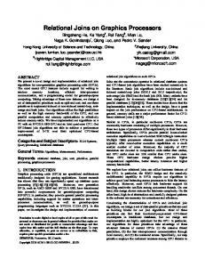
Fig. 1. Illustration of SEER. (a) Interference from heterogeneous devices is common in the ISM band. SEER changes channel at frame-level to avoid interference. (b) When switching to a new band, SEER prepends a lightweight preamble to indicate the new transmission band. The preamble can be detected even it is transmitted in the receiver’s outband spectrum.
tation in current wireless devices. State-of-the-art solutions either focus on spectrum adaptation within the transceiver’s radio frequency (RF) band (inband) [4], [7], [8] or require central coordination with substantial overhead that prevents frame-level adaptation [3], while the capability of adapting spectrum efficiently and promptly over a wideband is still missing. Without efficient wideband spectrum adaptation, wireless devices’ operating channels cannot be fully unleashed to support flexible spectrum access over multiple channels, which is envisioned as “sharing wide spectrum superhighways” by the Federal Communications Commission (FCC) [1] and the President’s Council of Advisors on Science and Technology (PCAST) [2]. The target of this paper is to fill the gaps in wideband spectrum adaptation: we argue that frame-level wideband spectrum adaptation can be realized on commodity radios with lightweight overhead. To achieve this goal, the following requirements should be satisfied. First, there should be no extra coordination for spectrum agreement. Since spectrum adaptation is made at frame-level due to fast fading and traffic dynamics, extra coordination (control messages and channels) should be avoided to minimize overhead. Second, it should be protocol independent. Spectrum adaptation should not rely on specific protocols to maximize the chance of its widespread acceptance. As such, spectrum adaptation can be transplantable to different protocols with only minimal modifications. Finally,
II. D ESIGN OVERVIEW The system architecture of S EER is shown in Fig. 2. S EER provides wideband spectrum adaptation capability to wireless devices by adding a decoupled baseband processing layer,
Legacy Protocol
Spectrum Adaptation
RF Front-End
No adaptation
MAC
PHY
Spectrum Manager
Preamble Generator Spectrum Detection
Aliasing Recovery
DAC
DAC
Preamble Detector
RF DAC
it should be easily applied to commodity radios without adding extra hardware. As a result, wideband spectrum adaptation could be smoothly integrated into commercial devices. To fulfill the aforementioned requirements, this paper introduces S EER (SpEctrum adaptation in widEband without cooRdination). As illustrated in Fig. 1, S EER adds a widebanddetectable preamble prior to the data frame to indicate the new transmission band. This preamble is directly prepended to the data frame and is sent and received through the same RF chains used for data transmission. As such, S EER can be applied to different protocols (e.g., OFDM-based protocols and DSSS-based protocols) and can be realized without extra hardware. This preamble design eliminates the need for extra control messages, separate control channels, or a central coordinator. However, it is non-trivial to design such a preamble. A fundamental obstacle is that current radio designs cannot detect signals beyond its RF band (outband signals): wideband spectrum folds up under aliasing, making signals unrecoverable. Though several recent efforts [9]–[12] can recover signals with certain sparsity properties, they cannot be applied to general cases as the commonly-used spectrum (e.g., the ISM band) is overcrowded. S EER overcomes this limitation by designing a specially-structured preamble that sustains the sparsity property at a high-power level even when the spectrum is crowded. Another challenge is to use the preamble to notify a S EER receiver of the spectrum occupied by the coming frame in the context of multiple asynchronous senders. Since a S EER receiver needs to switch to the desired spectrum to decode the data frame, spectrum detection should be performed within the preamble time. To this end, S EER exploits the preamble’s temporal and spectral properties to identify the intended spectrum. The main contributions of this paper are summarized as follows. First, we propose a detailed design for frame-level wideband spectrum adaptation on commodity radios without adding extra hardware. It can be easily integrated to existing devices of different protocols by simply adding spectrum adaptation functions. Second, we implement S EER on the GNURadio/USRP platform to validate the feasibility of our design. To the best of our knowledge, it is the first frame-level wideband spectrum adaptation prototype. Finally, we conduct trace-driven simulations to demonstrate the merits of framelevel wideband spectrum adaptation. The reminder of this paper is structured as follows. We begin in Section II with the design overview. Section III describes the detailed preamble design to combat frequency aliasing, and Section IV elaborates on the preamble-based spectrum adaptation scheme. System implementation and performance evaluation are presented in Section V. Section VI reviews related work, followed by conclusion in Section VII.
ADC
No preamble
SEER Fig. 2. Architecture of a S EER transceiver.
referred to as the spectrum adaptation layer, between the legacy physical/media access layer (PHY/MAC) and the RF front-end. The PHY/MAC in a S EER transceiver exposes an interface to the spectrum adaptation layer to allow streams of complex digital baseband samples flowing between the layers. The spectrum adaptation layer adds or removes extra preambles to those baseband samples for spectrum detection while tuning the RF band through the RF front-end. By decoupling spectrum tuning and detection from packet decoding and scheduling, the legacy PHY/MAC works independently and the spectrum adaptation functionality can be integrated into wireless devices without modifying the radio. To realize the above abstraction, S EER employs several key components in the spectrum adaptation layer, as depicted in Fig. 2. In the transmitter mode, the preamble generator prepends a specially-constructed preamble to the data frame to convey spectrum information when the transmission band changes. In the receiver mode, S EER devices first detect the specially-designed preamble using the preamble detector, and then identify the new transmission band in two steps: aliasing recovery and spectrum detection. The spectrum manager executes a protocol that decides the spectrum band for packet sending and receiving. Thanks to recent advances in fast channel sensing (e.g., fast wideband sensing [10], [13], probing-free channel tracking [6]) and lightweight feedback (e.g., limited feedback [14], side channels [15], [16]), the best channel can be obtained at low cost. The spectrum manager is built atop these techniques to acquire channel quality information. In the transmitter mode, the spectrum manager determines the transmission band based on the channel quality information, and notifies the preamble generator and the RF front-end if the transmission band changes. In the receiver mode, when the change in the transmission band is detected by the spectrum detector, the spectrum manager tunes the RF band to the detected spectrum for packet receiving. S EER still conforms to the legacy PHY/MAC for packet transmission and channel access. For example, a Wi-Fi based S EER device still needs to contend new channels according to the IEEE 802.11 protocol: after a sender switches to a new transmission band, it still performs CSMA (carrier sense multiple access) protocol as a legacy Wi-Fi node. The core and challenging part of S EER is to design a preamble that exchanges spectrum information between transceivers.
In particular, the preamble must satisfy the following two requirements. First, the preamble should be detectable and recoverable by a S EER receiver with an arbitrary RF band located in a wide overcrowded spectrum. To support wideband spectrum adaptation without coordination, the preamble must be able to deliver the spectrum information even if the corresponding receiver’s RF band is different from the transmission band used for the preamble and the following data frames. Normally, a receiver can only receive and decode inband signals, or sparse signals outside its RF band using sparse recovery techniques. However, the spectrum open to wireless networks is usually overcrowded (e.g., the ISM band), making the outband signals unrecoverable by directly using existing techniques. Note that though several fairly recent advances [10], [17] have provided solutions for non-sparse spectrum recovery, they are only applicable to limited scenarios like differentiallysparse spectrum [10] or constellation-sparse signals [17]. To overcome this limitation, in Section III, we design a speciallystructured preamble to be recoverable by the receiver whose RF band is different from the sender’s. Second, a S EER receiver can identify the transmission band of its intended frames in the presence of multiple S EER senders. Since preambles are detectable in a wide band, a S EER receiver may detect multiple preambles in the context of multiple S EER senders. The S EER receiver should be able to screen irrelevant preambles and identify the intended transmission band. To support this feature, in Section IV, we elaborate on our design of preamble-based spectrum detection. III. H ARNESSING F REQUENCY A LIASING The first step towards realizing S EER is to design a wideband-detectable preamble. A fundamental challenge to achieve this goal is frequency aliasing. Modern wireless transceivers are fundamentally gated by the Nyquist rate: the sample rate of a receiver must be at least twice the signal bandwidth. Otherwise, the sample rate is insufficient to capture the changes in the signal, thereby causing frequency aliasing, that is, the signal spectrum folds up and becomes unrecoverable. Sparse recovery techniques [9], [10] can be leveraged to handle frequency aliasing, while the sparsity condition cannot be satisfied in the commonly-used spectrum which is overcrowded. To overcome the above hurdle, this section presents the design of a specially-structured preamble to create sparsity in overcrowded spectrum. A. Sparse Recovery Before presenting the design of the preamble, we first show how frequency aliasing is handled using the latest sparse fast fourier transform (FFT) technique [9], [10] in the case of sparse spectrum. Aliasing occurs when a receiver captures a spectrum band wider than its own RF band. In particular, when the receiver uses a low-speed analog-to-digital converter (ADC) to subsample wideband signals, the wideband signals fold up into the
RF band. Formally, denote the width of the RF band as F , the bandwidth of the signal as W = N ·F (N > 1, N ∈ Z). Then, the relationship between the signal’s frequency representation s and the sub-sampled version s0 is given by s0i =
N −1 X
si+nF ,
(1)
n=0
where i is the index for a discrete frequency point in the signal’s frequency representation. When a wideband signal is sparse in the frequency domain, i.e., si = 0 for most frequency points. Then, for a non-zero frequency point s0i , it is highly-likely to contain only one frequency point si+kF , j ∈ {0, ..., N − 1}. In this case, the real frequency position f = i + kF can be derived by shifting s0i in the time domain, which causes phase rotation in the frequency domain. After shifting the input signal by τ samples, the phase rotation ∆θ of s0i can be used to compute the real frequency position f by: f = ∆θF/(2πτ ). (2) A combination of different delays can be used to resolve collisions. For two different signals si and si0 that collide at the same sub-sampled frequency position, we can shift the sub-sampled signals twice to obtain the following equation set: 0 = si + si0 c 0 τ1 (3) c = si ej2πf τ1 /F + si0 ej2πf τ1 /F 0 τ2 j2πf τ2 /F j2πf τ /F 2 c = si e + si0 e where c0 , cτ1 , cτ2 are collided signals at the receiver, and f, f 0 are frequency points of si , si0 , respectively. Since there are limited number of possible frequency pairs (f, f 0 ), this equation set is solvable. However, the above technique works well only for sparse spectrum (or differentially sparse spectrum). Unfortunately, the commonly-used spectrum for wireless networks, e.g., the ISM band, is normally overcrowded. In an overcrowded spectrum, most of the frequency points are non-zero, and thus a subsampled frequency point normally consists of many different frequency points, making it unlikely for the receiver to recover the real frequency positions. Note that though several fairly recent advances [10], [17] have provided solutions for non-sparse spectrum recovery, they are only applicable to limited scenarios like differentially-sparse spectrum [10] or constellation-sparse signals [17]. B. Creating Sparsity in Overcrowded Spectrum To create sparsity in an overcrowded spectrum, we design a preamble structure consisting of multiple narrowband signals. Our insight is that even in overcrowded spectrum, high-power signals are still sparse, which is consistent with the measurement results reported in [18]. Then, if we can transmit the preamble using high power, the preamble can be considered as a sparse signal at a high-power level. Nevertheless, as the transmission power is limited for a certain device, we cannot simply increase the transmission power to generate
A1 A2
−60 −80 −100 −120 0
200
400
600
Frequency index
800
C. Generating δ-Preamble
−40
B1 B2
Power (dBm)
Power (dBm)
−40
B1
A1
B1
A2
−80 −100 −120 400
1000
(a) Two concurrent δ-preambles A (red) and B (blue) in 25MHz band.
−60
450
500
550
Frequency index
600
(b) Received δ-preambles at receivers with 5MHz bandwidth.
Fig. 3. δ-preambles in the frequency domain. Results are taken from a measurement conducted using USRP testbeds. Each δ-preamble consists of two subband signals, which fold up in a 5MHz band (400-600 indices) at the receiver.
Narrowband signals Signals from a neighbor channel
−60 −80 −100 −120 0
200
400
600
Frequency index
800
1000
(a) Transmitted 25MHz signals.
−40
Power (dBm)
Power (dBm)
−40
Sparse at −70dBm
−60 −80 −100 −120 400
Overcrowded at −90dBm
450
500
550
Frequency index
600
(b) Received signals at receivers with 5MHz bandwidth.
Fig. 4. Frequency aliasing. Frequency samples are taken from a measurement conducted using USRP testbeds. High-power narrowband signals create new sparsity in crowded spectrum.
high-power preambles. While prior studies [5], [16] have made the observation that a sender using a narrower channel can transmit higher magnitude signals. Based on this observation, we design δ-preamble (named after the Dirac delta function) which consists of multiple narrowband “pulses” in the frequency domain, as depicted in Fig. 3. We divide a channel into M equal-width subbands. For example, a 40MHz channel can be divided into 20 subbands of 2MHz bandwidth. Let P pm denote the power of the mth M subband. Then, we have m=1 pm ≤ P , where P is the total transmission power of the receiver. Thus, the power of a subband is inversely proportional to the total bandwidth used for transmission. Based on this observation, we can generate multiple high-power subband signals using existing radios without requiring extra transmission hardware or signal processing logic. In our current implementation, for a 40MHz bandwidth transceiver, δ-preamble uses four subbands of 2MHz bandwidth to transmit at 5× greater power than the power used for data transmission. The higher magnitude of subband signals creates new sparsity in the frequency domain. As illustrated in Fig. 4, signals from neighboring channels fold up into the receiver’s band, resulting in a crowded band full of non-zero frequency points (signals above -90dBm). However, if we raise the bar to -70dBm, the spectrum is sparse: only three high-power subband signals are above the bar. Then, we can leverage the sparse recovery technique to recover the frequency position of each subband signal in δ-preamble.
The δ-preamble can be easily implemented using existing radios without adding extra hardware. Our goal is to generate multiple concurrent subband signals using fixed RF front-end hardware. To generate δ-preamble using the RF front-end, we take the following two steps: 1. Generating pulses. Suppose that the spectrum manager has decided to use which M 0 subbands out of a total of M subbands to place pulses. According to [19], we interpolate digital samples of each signal by adding M − 1 duplicated samples, which decreases the bandwidth of the baseband signal to the ratio of 1/M . As the interpolation process creates aliasing signals, an LPF is added to remove the undesired aliasing signals. 2. Placing pulses. Step 1 creates subband pulses at the central frequency. To generate the δ-preamble, wePneed to n place pulses at corresponding subbands. Let s = i=0 s[i] be a pulse signal generated in Step 1, and f be the baseband frequency of the desired subband. To place s in the desired subband, we can simply multiply a frequency offset factor to to derive a frequency shifted signal ˆ s = Pneach sample j2πif s[i]e . Finally, all pulses are added together before i=0 feeding them into the digital-to-analog converter (DAC), and are transmitted at the sender’s carrier frequency. Note that similar techniques have been used to reshape the spectrum for data transmission [7], [20]. IV. S PECTRUM D ETECTION AND A DAPTATION Given the capability of generating the wideband detectable δ-preamble, the next question is how to leverage the δpreamble to detect the bandwidth and central frequency of the intended transmission band. We answer this question in this section. We first show how to encode the spectrum information and the receiver’s signature into the δ-preamble, and then elaborate on the algorithms for preamble detection and transmission band identification. A. Spectrum Information Encoding Before we start to describe the preamble encoding strategy, we first specify the rules that senders follow to choose the transmission bands. • Rule I: A subband is regarded as a basic unit for spectrum adaptation, and a transmission band is a continuous spectrum band that consists of a set of consecutive subbands. • Rule II: The bandwidth of a transmission band is no wider than the maximal bandwidth supported by the intended receiver’s RF front-end. According to these two rules, a transmission band is represented by a set of consecutive subbands sub {Blsub , Bl+1 , ..., Brsub }, which can be indicated using a pair of subbands at the band’s boundaries (Blsub , Brsub ). Then, the target of spectrum detection is to identify a pair of subbands (Blsub , Brsub ) in the wideband spectrum. To this end, we encode the spectrum information by simultaneously utilizing the frequency structure and temporal correlation.
Frequency structure encoding. The δ-preamble consists of multiple subband pulses. S EER utilizes the frequency positions of the pulses to indicate the spectrum band used for data transmission. In our implementation, a δ-preamble contains four pulses. We place two pulses in the two boundary subbands Blsub and Brsub , and the other two pulses in random subbands. In particular, we cut the total transmission band in half, and randomly select one subband from each half band to place a pulse. The distance between a randomly placed pulse and the boundary subband in the same half band is encoded in the signal of the randomly pulse. The benefits of this strategy are twofold. First, it largely reduces aliasing collision probability when senders select the same bandwidth. Note that though we can recover signals from aliasing collision with high probability, reducing the aliasing collision probability will further improve the recovery rate. In addition, it provides redundancy in boundary subband identification. In particular, we use two pulses, i.e., a pulse placed in the boundary subband and a pulse placed in a random subband, to encode the same boundary subband position. We leverage this redundancy to set extra constraints in the frequency recovery. To encode the position information in the pulse signals, the encoding strategy must possess the following features. • Robust decoding. Since frequency aliasing causes collisions and interference, the coding scheme must be very robust to combat strong interference. The modulation and coding schemes used for data transmission fail to satisfy this requirement as these schemes normally require high SIR for synchronization, channel estimation, and data decoding. • Frame destination recognition. In the context of multiple S EER transmissions, intended frames must be recognized within the preamble time. Otherwise, the receiver cannot switch to the correct transmission band for data decoding. One might think of buffing all data samples first and then adopting trial-and-error to find the right data frame. However, this approach is inapplicable since aliased high bit-rate data signals are unrecoverable. To fulfill the above requirements, S EER employs a temporal correlation encoding strategy to convey the pulse position information and receivers’ signatures. Temporal correlation encoding. Motivated by the robust synchronization and sender recognition mechanism adopted in cellular networks, S EER leverages polyphase sequence [21] to encode the pulse position information. Polyphase sequences have long been used in many air interfaces in cellular networks to reduce the cross-correlation of simultaneous transmissions. In practice, the Walsh-Hadamard codes and the Zadoff-Chu sequences (ZC sequences) [22] are used in the Universal Mobile Telecommunications System (UMTS) and the Long Term Evolution (LTE), respectively. In this paper, we select the ZC sequence, which is defined as: s(u, k)[n] = e−j2πu
(n−k)(n−k+1) 2Nz
,
(4)
where Nz is the sequence length, n = 0, 1, ..., Nz − 1, and k the cyclical-shift parameter. The sequence index u can be
s(2,0)
s(7,3)
3 subbands
s(4,0)
s(3,4)
Pulse
4 subbands
Transmission band
Frequency
Fig. 5. Encoding spectrum information using δ-preamble.
any integer between 1 and Nz that is a relative prime to Nz . The ZC sequence exhibits the following desirable properties: i) The auto correlation of a prime length ZC sequence with a cyclically shifted version of itself is zero, and ii) The cross-correlation √ between two prime length ZC sequences is a constant 1/ Nz , given that the index difference is relative prime to Nz . These strong correlation properties make the ZC sequence ideal for identification: as proposed in the LTE, a unique pair (u, k) can be assigned to a device as its signature. In our design, we divide the pair (u, k) of a ZC sequence into two dimensions: the sequence index u is used to identify the frame destination, and the cyclic-shift parameter k is used to indicate the pulse position. Recall that a δ-preamble consists of M 0 pulses that can be expressed as an array of ZC sequence [s(u1 , k1 ), ..., s(uM 0 , kM 0 )]. S EER uses the array of sequence indices [u1 , ..., uM 0 ] as a receiver’s signature, and the cyclicshift parameter ki of a pulse s(ui , ki ) to indicate the number of subbands between the pulse s(ui , ki ) and the boundary subband in the same half band. Fig. 5 shows an example of how to encode a δ-preamble consisting of four pulses, where the receiver’s signature is [2, 7, 3, 4]. After successfully detecting the spectrum, the S EER receiver switches channel to the new band to receive the incoming frames. Since channel switching incurs extra delay (e.g., 25µs [23]), which requires a time gap between the δ-preamble and the frame to allow the receiver to switch to the new band before frame transmission. We repeat the δ-preamble multiple times to fill the gap for channel reservation. Ambiguity and collision. In the centralized mode, such as enterprise WLANs, signatures are assigned by a central controller to avoid signature ambiguity. While in ad hoc mode, each S EER node randomly picks an array [u1 , ..., uM 0 ] as its signature. In both modes, signatures are exchanged during association. We set Nz to be a prime number (e.g., 17, 37) thereby allowing u to be any integer between 1 and Nz . Thus, 0 there are a total of NzM different arrays that can be used as signatures. The probability of two S EER nodes selecting 0 the same signature is 1/NzM , which is significantly small. 0 In our implementation, the probability is 1/NzM = 1/174 = 1.2 × 10⁻⁵ . Collision occurs only when two collided pulses select the same (u, k) pair, which is highly unlikely to occur because it requires that all of the following four events occur at the same time: i) two S EER senders send δ-preamble simultaneously, ii) two pulses are aliased at the receivers, iii) two pulses
pick the same sequence index u, and iv) two pulses have the same distance to the boundary subband (i.e., use the same cyclic-shift parameter k). Therefore, ambiguity and collision of concurrent transmitted δ-preambles occur with only very small probabilities, thereby having minimal impact on the performance of S EER. B. Preamble Detection The relatively high power of pulses make them easy to detect. A S EER device leverages the energy detection method that is inherently enabled by the device. For example, an IEEE 802.11 device detects the start of an incoming signal PL by mea2 suring the energy of the sampled signal s: Ps = k=1 |s[k]| , where L is the measuring window. The high-power pulses are easy to detect by this method when there is no frequency aliasing. However, when the receiver’s band is filled with aliased signals, Ps can be higher than the threshold even if there is no pulses. In this case, the incoming pulses cannot be detected by comparing Ps with the threshold, thereby causing false negatives. To address this predicament, S EER uses the differential rather than the absolute values of Ps for energy detection. When the incoming signals are detected, the receiver computes the power spectral density by performing fast fourier transform (FFT), and then recover the frequency positions of pulses. After the pulse detection, a S EER receiver then determines: i) whether the incoming pulse is from the intended sender, and ii) what is the central frequency and bandwidth used for the following data transmission. In particular, S EER parallelly correlates each pulse signal samples with the Nz sequences in a pipeline fashion, which processes the incoming sample sequence sample by sample in real time and derives the correlation results roughly at the same time when all samples are received. After identifying the parameters (u, k) of pulses, the receiver executes sequential search to find a matched signature. If there are T concurrent transmitters, the sequential searching takes O(M 0 T ) time. There are two extra constraints that further narrow down the search space: i) the frequency separation between pulses in a signature must be consistent with cyclic-shift parameters, ii) the cyclic-shift parameters of boundary pulses are zero. C. Spectrum Adaptation Overhead The spectrum adaptation latency is mainly caused by the preamble detection and channel switching. The airtime for δNz . In our design, preamble transmission is proportional to W s we set Nz = 17 and Ws = 2MHz, which results in 8.5µs airtime for δ-preamble transmission. Recall that the preamble detection algorithm takes O(M 0 T ) time where T is the number of concurrent S EER senders and M 0 is the number of pulses in a δ-preamble. When there are five concurrent S EER senders, the preamble detection algorithm takes merely 0.5µs with a 40MHz digital signal processor (M 0 = 4 in our implementation). Hence, the latency incurred by the preamble detection is 8.5 + 0.5 = 9µs, which pays an overhead of
only 1.9% (with MAC overhead considered) to a typical IEEE 802.11 packet transmission at 54Mbps. Channel switching latency is mainly contributed by the lock-in time of the phase-locked loop (PLL) used by the transceiver’s chipset. The off-the-shelf 802.11 chipset incurs 25µs latency for channel switching within 100MHz range [23], while the state-of-the-art in solid state electronics has shown that this latency can be less than 22µs for channel switching within 1.9GHz [24]. These delays could be further reduced in future integrated circuit (IC) designs. Therefore, the overall spectrum adaptation latency is 9 + 22 = 31µs, which is merely 6.7% of the total time used for a 54Mbps 802.11 packet transmission. Recall that recent advances have made it feasible to promptly acquire channel availability and quality in a wide spectrum with low overhead. For example, scanning a 0.9GHz spectrum to acquire channel availabilities takes merely 1µs with commodity ADCs [10], and reliably estimating the strongest channel from a set of channels only requires measurements collected on a single channel without probing extra channels [6]. Therefore, we conclude that finding and adapting to the best spectrum are fast enough to enable frame-level spectrum adaption. D. Spectrum Adaptation Strategy The Spectrum manager in S EER determines the spectrum adaptation strategy. The spectrum adaptation is desirable only when the spectrum availability or channel quality vary. To avoid unnecessary overhead, a S EER sender transmits legacy frames unless i) the current channel is occupied, or ii) the signal-to-noise ratio (SNR) of the current channel is below a threshold. These two conditions trigger the sender to adapt to a new channel, in which case the S EER sender still conforms the legacy PHY/MAC, e.g., CSMA, to access channel. V. E VALUATION A. Implementation S EER can be realized in existing OFDM PHY with no hardware changes. We implement the entire baseband design of S EER directly in the USRP Hardware Drive (UHD). Nodes in our experiments are USRP N210 devices equipped with RFX2450 daughterboards as RF frontend, which operate in the 5.1-5.2GHz range. We have empowered the δ-preamble generation and detection, frequency aliasing recovery, and spectrum detection using the GNURadio/USRP platform. Due to the large processing delay of USRP hardware and limited power of general purpose processor, the spectrum adaptation strategy cannot be performed in real-time on USRP. Thus, we emulate the spectrum adaptation strategy offline using the signals captured by the spectrum measurements from [18]. B. Frequency Recovery Performance A basic primitive of S EER is to recover the frequency of pulses using the method described in Section III. In this experiment, we use USRP testbeds to verify the robustness of frequency recovery in different SIR environments and the presence of concurrent senders.
0.94 0.92
2
3
4
5
6
7
8
9
10
0
11
5
0.95
0.03
TP, Nz = 17
0.9
0.02
TP, Nz = 37 FP, Nz = 17
0.85
0.8 0
0.01
FP, Nz = 37
2
4
6
8
10
0
10
15
20
0.05 X: 0 Y: 0.0264
−5
0
0 10
5
SIR(dB)
Fig. 8. TP and FP rates under various SIR.
1
0.05
1
0.95
0.04
0.95
0.9
0.03
0.9
TP, Nz = 17 TP, Nz = 37
0.85
0.1
FP, Nz = 37
0 −10
Fig. 7. Frequency recovery accuracy under various number of subbands per channel.
TP rate
0.04
FP rate
TP rate
1
TP, Nz = 37 0.4
SIR (dB)
Number of Concurrent senders
Fig. 6. Frequency recovery accuracy under various number of concurrent senders. SIR = 5dB.
FP, Nz = 17
0.2
0.9 1
0.15
TP, Nz = 17 0.6
0.02
0.04
TP, Nz = 17
0.03
TP, Nz = 37 FP, Nz = 17 0.02
FP, Nz = 37 0.85
FP, Nz = 17 FP, Nz = 37
0.8
0.75
4
6
8
10
12
14
0.01
16
18
20
0
Number of concurrrent senders
Number of subbands per channel
Fig. 9. TP and FP rates under various number of concurrent senders. SIR = 5dB.
Fig. 10. TP and FP rates under under various number of subbands per channel. The number of concurrent senders is 5. SIR = 5dB.
Experimental setup. Due to the limited bandwidth and capacity of USRP, we set a channel as 5MHz instead of 20/40MHz as considered in our design. The transmitted signals are spread in a 25MHz band between 5.1-5.2GHz, and a receiver’s bandwidth is set to 5MHz. Unless otherwise stated, a channel is divided into ten subbands. We use a USRP to send 5MHz frames back-to-back in an adjacent channel to generate aliased interference. The USRP nodes are placed at different locations in a 10m × 10m office. The experiment is repeated 10,000 times to compute recovery accuracy. We compare the proposed approach (S EER) that is tailored to pulse recovery with a baseline approach (sFFT) that directly applies the state-of-the-art sparse FFT technique [10] without considering sidelobe issues and pulse redundancy. Impact of concurrent senders. In Fig. 6, we keep SIR = 5dB and vary the number of concurrent S EER senders, who randomly select 5MHz from the total 25MHz band to send δ-preambles. The results show that the encoding scheme proposed in this paper yields more than 90% accuracy for less than four concurrent senders. Note that the chance is rare for more than five senders sending frames simultaneously in one channel. Besides, more concurrent senders can be supported when the number of subbands in one channel is larger (i.e., in a wider channel). Thus, we claim that the frequency recovery function of S EER works well in the presence of multiple senders. Impact of number of subbands. Fig. 7 shows the recovery accuracy of S EER under different number of subbands in each channel.The number of subbands stands for the frequency estimation granularity. The results show that the it is more
0.01
0.8
0.75
FP rate
0.2 0
0.96
TP rate
0.4
0.2
0.8
20 subbands 10 subbands 5 subbands
FP rate
0.6
0.98
TP rate
Recovery accucacy
Recovery Accuracy
0.8
1
FP rate
1
1
8
12
16
20
24
28
32
36
40
0
Channel width (MHz)
Fig. 11. TP and FP rates under channels with various bandwidths.
robust to divide a channel into less subbands due to the lower granularity requirements. However, reducing the number of subbands involves a adaptation flexibility penalty, as the subband is the basic unit in spectrum adaptation. The figure also shows that the performance of S EER using 10 subbands/channel exhibits only minor degradation with respect to the performance using 5 subbands/channel. We conclude that 10 subbands/channel provides a good compromise between adaptation flexibility and recovery accuracy. C. Spectrum Detection Performance Experimental setup. We evaluate the spectrum detection performance of S EER using USRP testbeds with the same setup as for frequency recovery evaluation. We use two metrics: true positive (TP) rate, i.e., the probability of correctly detecting the intended spectrum, and false positive (FP) rate, the probability of falsely recognizing other senders as the intended sender. Impact of SIR. Fig. 8 shows the spectrum detection accuracy using different sequence lengths Nz . We see that for SIR ≥ 0, the TP rates of two sequences are higher than 97%, while the FP rates are lower than 2.6%, which demonstrates that S EER can detect spectrum with extremely high accuracy in a wide SIR range. Note that the frame delivery rate of Wi-Fi transmissions at SIR = 0dB is less than 10%. Thus, we conclude that S EER yields high accuracy in spectrum detection even in severe interfered channels. Impact of concurrent senders. Fig. 9 evaluates the spectrum detection performance of S EER in the presence of multiple concurrent senders. A various number of concurrent
30
20 15 10
FIXED INBAND SEER
8
25 20 15 10
6
4
2
5 0 4.45
30
Throughput (Mbps)
35
Throughput (Mbps)
Throughput (Mbps)
25
10
40
FIXED INBAND SEER
5
4.65
4.85
5.05
5.25
5.45
5.65
5.85
0 4.45
Frequency (GHz)
4.65
4.85
5.05
5.25
5.45
5.65
0
20
100
200
300
400
Searching bandwidth (MHz)
Frequency (GHz)
(a) Throughput comparison using 20MHz channel. (b) Throughput comparison using 40MHz channel. (c) Average throughput of S EER under different searchSearching bandwidth of S EER is 100MHz.
Searching bandwidth of S EER is 200MHz.
ing bandwidth. Channel width is 20MHz.
Fig. 12. Throughput of S EER using the 1.6GHz wide spectrum availability trace.
senders randomly select a channel to transmit δ-preambles, which are aliased at the receiver’s RF band. The results show that when the number of concurrent senders is no more than 5, S EER achieves the TP rates higher than 94% and the FP rates lower than 3.7%. When the number of concurrent senders is increased to 10, the TP rate of S EER with Nz = 17 drop to 82%, while the FP rate is still less than 4%. Regarding that the chance of more than 5 concurrent senders is very low (e.g., CSMA-based networks use random backoff mechanism to avoid collision), S EER achieves high accuracy in most cases. Impact of number of subbands and channel width. Fig. 10 shows the spectrum detection accuracy as a function of the number of subbands per channel. The number of concurrent senders is set to be 5. The detection accuracy goes up with the number of subbands per channel as there are less collision probability. When the number of subbands per channel is larger than 10, S EER with different Nz achieves TP rates over 94% and FP rates below 4%, which shows that dividing a 20MHz channel into ten 2MHz subbands is a feasible setting. Fig. 11 shows that S EER performs better in wider channels, as there are more subbands in one channel. D. Wideband Spectrum Adaptation Performance The objective of this section is to show the efficacy of S EER in promptly adapting spectrum according to channel availability and quality variances. Due to the processing delay, USRP cannot support real-time MAC layer protocols. Thus, we turn to trace-driven simulations for evaluation. Simulation methodology. To study the performance of S EER, we take Wi-Fi networks as a study case and implement an emulator to model the CSMA/CA MAC as in 802.11. We compare S EER with two baseline approaches: fixed channelization (FIXED) and inband spectrum adaptation (INBAND). FIXED selects the operating channel based on initial measurements and will not change channels during the simulation. INBAND is capable of per-frame inband adaptation as described in [7]. We take into account the spectrum adaptation overhead (31µs) when simulating S EER. For fair comparison, we adopt the same spectrum adaptation strategy as described in Section IV-D for INBAND and S EER. INBAND can use noncontinuous fragments in a channel while S EER can use a continuous band over a wide spectrum.
Channel availability trace. We use extensive spectrum occupancy measurements provided by [18] as channel availability trace. We select the channel measurements that span a 1.6GHz wide spectrum centered at 5.25GHz, which indicate the 5GHz ISM band usage pattern. Measurements are collected using Agilent E4440A spectrum analyzer which sweeps over the 1.6GHz spectrum every 1.8s with a granularity of 200KHz. Note that the 1.8s interval is sufficient to capture the channel usage pattern [25]. Evaluation of S EER under channel availability variance. Fig. 12 evaluates the performance of S EER using the channel availability trace. We assume that there is a single transmission link with saturated traffic. The sender transmits 1000B frames at 54Mbps. All approaches can use up to one channel bandwidth to transmit frames. S EER can select a channel from a wide band, whose bandwidth is referred to as searching bandwidth. The searching bandwidth of S EER is set to be the width of five channels in Fig. 12(a) and Fig. 12(b), but varies in Fig. 12(c). The 1.6GHz spectrum is divided into continuous 20/40MHz channels. Fig. 12(a) and Fig. 12(b) compare the throughput in all channels of the 1.6GHz spectrum. The results show that in the entire 1.6GHz spectrum, S EER significantly outperforms INBAND and FIXED. In the range of 4.45-5.45GHz, where the spectrum is heavily-used, FIXED and INBAND do not have enough flexibility to avoid pervasive interference, while S EER is still able to find short transmission opportunities. Fig. 12(c) evaluates the impact of searching bandwidth on S EER’s performance. We randomly select a central frequency in the 1.6GHz spectrum and repeat simulations to obtain the average throughput. The figure shows that the average throughput increases with the searching bandwidth, which demonstrates the benefits of wideband spectrum adaptation. VI. R ELATED W ORK Dynamic spectrum access. Dynamic spectrum access allows devices to dynamically change their operating central frequency and spectrum bandwidths. Chandra et al. [5] have shown that it is beneficial for Wi-Fi nodes to adapt channel width according to transceiver’s requirements and environmental conditions. Jello [26] extends bandwidth adaptation to non-continuous channel bonding in the case of narrowband
interference, but it requires coordination for spectrum agreement. Yun et al. [7] devise an efficient per-frame spectrum adaptation solution for Wi-Fi networks by exploiting the 802.11 preamble structure. These studies demonstrate that dynamically changing channel width and central frequency largely improves throughput compared with fixed-channel configurations. However, these solutions are limited to spectrum adaptation within the receiver’s RF band, and none of them supports outband spectrum adaptation. Spectrum virtualization. Spectrum virtualization is proposed in many recent works [4], [8], [20] to change spectrum in baseband without RF modifications. These solutions leverage signal shaping techniques such as sampling rate conversion and frequency shifting to change spectrum with little overhead. Picasso [20] and SVL [4] create an extra spectrum shaping layer for general wireless devices. However, they do not consider spectrum agreement between the sender and receiver. RODIN [8] uses an extra FPGA-based spectrum shaper and a new preamble to enable per-frame spectrum adaptation and agreement on commercial devices. S EER is is complimentary to these spectrum virtualization techniques by enabling outband spectrum adaptation. Sparse Recovery. Our outband signal detection design follows on the heels of sparse FFT [9], [10] and compressive sensing techniques [11], [12]. BigBand [10] is the first work to utilize sparse FFT to realize GHz-wide realtime spectrum sensing. Similar to sparse FFT, compressive sensing techniques [11], [12] achieve sub-Nyquist sampling by adding an extra GHz analog mixer before low rate ADC to perform high-speed complex analog matrix multiplications and analog mixing. S EER is fundamentally different from these sparse recovery studies in that these sparse recovery proposals focus on spectrum sensing and are not capable of differentiating the transmitter of a certain spectrum, and thus it cannot be directly applied to outband spectrum adaptation. VII. C ONCLUSION This paper presents S EER, the first system design and prototype for frame-level wideband spectrum adaptation. S EER leverages a specially-constructed preamble and a robust spectrum detection scheme to support coordination-free spectrum adaptation in wide spectrum beyond the receiver’s RF band. We have prototyped S EER using the GNURadio/USRP platform, and demonstrate its feasibility and substantial benefits through extensive experiments and simulations. We hope the design of S EER can contribute the wireless community by improving the spectrum efficiency to mitigate overcrowding of unlicensed spectrum usage. S EER can be realized on commodity radios and integrated into wireless devices running different protocols without requiring extra hardware. S EER is a clean solution that is independent and transparent to PHY/MAC protocols. We believe that with these features, S EER can be easily applied to a widerange of devices.
ACKNOWLEDGEMENT The research was support in part by grants from 973 project 2013CB329006, China NSFC under Grant 61173156, RGC under the contracts CERG 622613, 16212714, HKUST6/CRF/12R, and M-HKUST609/13, as well as the grant from Huawei-HKUST joint lab. R EFERENCES [1] FCC, “Second memorandum opinion and order (FCC 10-174),” 2010. [2] PCAST, “Report to the president: Realizing the full potential of government-held spectrum to spur economic growth,” 2012. [3] S. Rayanchu, V. Shrivastava, S. Banerjee, and R. Chandra, “FLUID: improving throughputs in enterprise wireless lans through flexible channelization,” in Proc. ACM MobiCom, 2011. [4] K. Tan, H. Shen, J. Zhang, and Y. Zhang, “Enable flexible spectrum access with spectrum virtualization,” in Proc. IEEE DySPAN, 2012. [5] R. Chandra, R. Mahajan, T. Moscibroda, R. Raghavendra, and P. Bahl, “A case for adapting channel width in wireless networks,” in Proc. ACM SIGCOMM, 2008. [6] S. Sen, B. Radunovic, J. Lee, and K.-H. Kim, “CSpy: finding the best quality channel without probing,” in Proc. ACM MobiCom, 2013. [7] S. Yun, D. Kim, and L. Qiu, “Fine-grained spectrum adaptation in WiFi networks,” in Proc. ACM MobiCom, 2013. [8] E. Chai, J. Lee, S.-J. Lee, R. Etkin, and K. G. Shin, “Building efficient spectrum-agile devices for dummies,” in Proc. ACM MobiCom, 2012. [9] H. Hassanieh, P. Indyk, D. Katabi, and E. Price, “Nearly optimal sparse fourier transform,” in Proc. ACM STOC, 2012. [10] H. Hassanieh, L. Shi, O. Abari, E. Hamed, and D. Katabi, “BigBand: GHz-wide sensing and decoding on commodity radios,” in Proc. IEEE INFOCOM, 2014. [11] J. Laska, W. Bradley, T. W. Rondeau, K. E. Nolan, and B. Vigoda, “Compressive sensing for dynamic spectrum access networks: Techniques and tradeoffs,” in Proc. IEEE DySPAN, 2011. [12] Y.-C. Chen, L. Qiu, Y. Zhang, Z. Hu, and G. Xue, “Robust network compressive sensing,” in Proc. ACM MobiCom, 2014. [13] S. Yoon, L. E. Li, S. C. Liew, R. R. Choudhury, I. Rhee, and K. Tan, “QuickSense: Fast and energy-efficient channel sensing for dynamic spectrum access networks,” in Proc. IEEE INFOCOM, 2013. [14] D. J. Love, R. W. Heath, V. K. Lau, D. Gesbert, B. D. Rao, and M. Andrews, “An overview of limited feedback in wireless communication systems,” IEEE J. Sel. Areas Commun., vol. 26, no. 8, 2008. [15] J. Zhang, H. Shen, K. Tan, R. Chandra, Y. Zhang, and Q. Zhang, “Frame retransmissions considered harmful: improving spectrum efficiency using micro-ACKs,” in Proc. ACM MobiCom, 2012. [16] A. Cidon, K. Nagaraj, S. Katti, and P. Viswanath, “Flashback: Decoupled lightweight wireless control,” in Proc. ACM SIGCOMM, 2012. [17] F. Lu, P. Ling, G. M. Voelker, and A. C. Snoeren, “Enfold: Downclocking OFDM in WiFi,” in Proc. ACM MobiCom, 2014. [18] M. Wellens and P. M¨ah¨onen, “Lessons learned from an extensive spectrum occupancy measurement campaign and a stochastic duty cycle model,” Mobile networks and applications, vol. 15, no. 3, 2010. [19] A. V. Oppenheim and R. W. Schafer, Discrete-time signal processing. Prentice-hall, 1989. [20] S. S. Hong, J. Mehlman, and S. Katti, “Picasso: flexible RF and spectrum slicing,” in Proc. ACM SIGCOMM, 2012. [21] P. Fan and M. Darnell, Sequence design for communications applications. Research Studies Press, 1996. [22] R. L. Frank, “Polyphase codes with good nonperiodic correlation properties,” IEEE Trans. Inf. Theory, vol. 9, no. 1, 1963. [23] Maxim, “MAX2828/MAX2829 world-band transceiver ICs datasheets,” http://datasheets.maximintegrated.com/en/ds/MAX2828-MAX2829.pdf. [24] J. Shin and H. Shin, “A 1.9–3.8 GHz fractional-N PLL frequency synthesizer with fast auto-calibration of loop bandwidth and VCO frequency,” IEEE J. Solid-State Circuits, vol. 47, no. 3, 2012. [25] V. Kone, L. Yang, X. Yang, B. Y. Zhao, and H. Zheng, “On the feasibility of effective opportunistic spectrum access,” in Proc. ACM IMC, 2010. [26] L. Yang, W. Hou, L. Cao, B. Y. Zhao, and H. Zheng, “Supporting demanding wireless applications with frequency-agile radios,” in Proc. USENIX NSDI, 2010.