Technion - Israel Institute of Technology, Haifa 32000, Israel. ABSTRACT. We consider sub-Nyquist sampling and Compressed Sensing (CS) for channel ...
2014 IEEE International Conference on Acoustic, Speech and Signal Processing (ICASSP)
CHANNEL ESTIMATION IN UWB CHANNELS USING COMPRESSED SENSING Kfir M. Cohen, Chen Attias, Barak Farbman, Igor Tselniker, Yonina C. Eldar Technion - Israel Institute of Technology, Haifa 32000, Israel ABSTRACT We consider sub-Nyquist sampling and Compressed Sensing (CS) for channel estimation in Ultra Wideband (UWB) communication systems, by exploiting the sparse nature of the channel impulse response. Receiver hardware schemes are presented that directly sample the analog channel output at rates far below Nyquist and allow access to a predefined subset of channel Fourier coefficients. CS methods are then applied to these coefficients in order to estimate the unknown channel. Simulations on Channel Model (CM) 1 of the IEEE 802.15.4a standard show that estimation is possible from low rate samples with little performance degradation paving the way to sub-Nyquist UWB channel sounding. Index Terms— Channel Estimation, Compressed Sensing, Sparse Recovery, Ultra wideband signaling, Analog to Projections 1. INTRODUCTION Ultra Wideband wireless communication [1] is a promising technique for conveying high rate data over short length wireless links. It gained interest since the US Federal Communications Commission [2] allowed usage of the unlicensed 3.1 − 10.6 GHz spectrum under restrictive power masks. Modulating low rate data onto larger bandwidth encapsulates many advantages, including frequency diversity, low outage link rate, and coexistence with other users. Direct Sequence (DS) spread spectrum is a common way to broaden the bandwidth, resulting in high processing gain that allows to suppress effective noise power. The entire 7.5 GHz unlicensed spectrum is too wide for current Analog to Digital Convertor (ADC) technology. For some needs, enough frequency diversity exists in smaller bandwidths. Following recommandations in [3], the spectrum may be sliced into nonoverlapping bands of 500 MHz (minimal bandwidth to be categorized as UWB), and operation can be restricted to one of these bands. Signaling over ultra wideband width results in very short time pulses (500 MHz translates into pulses of 2 ns). Effectively, this is the sampling rate needed to satisfy the Nyquist sampling theorem [4], where we assume down conversion is performed from the radio carrier into baseband. All channel effects beyond this bandwidth are irrelevant since power is not allocated on them. The bandwidth affects the performance through time resolvability: the higher the bandwidth, the denser the time grid of the samples. Indoor wireless mediums are dominated by many signal echoes, mainly caused by reflection, diffraction, and scattering of the electromagnetic waves. The varying nature of a typical environment has channel coherence time of milliseconds, enabling to consider packet based transmissions with the assumption that during a packet the channel is stationary. The channel can then be modeled as linear and time invariant and all calculations can be performed in the discrete channel model. If echoes happen to arrive in a time difference less than the sampling period, they are unresolvable and are summed
978-1-4799-2893-4/14/$31.00 ©2014 IEEE
1966
into a single tap of the discrete channel [5]. The summation can be destructive or constructive depending on their phase. The resulting discrete channel impulse response was studied in [6]. It was shown that several 802.15.4a channel models [7] [8] are sparse in the sense that many entries are close to zero. Motivated by this observation, the emerging field of Compressed Sensing (CS) [9] [10] [11] can be used to estimate the discrete channel impulse response. CS aims to recover an underlying signal x ∈ CN from linear measurements y = Ax where A ∈ CM ×N is called the measurement matrix, and M < N . The noisy version y = Ax + z,
(1)
where z is noise, is more common in real life measurements. In general, this problem is underdetermined and has infinitely many solutions. However, if the vector x is sparse, namely it contains a small number of nonzero values and A satisfies appropriate conditions [12], then with high probability only one sparse signal will match y. Sparse recovery techniques can then be used to estimate x. Here we consider Orthogonal Matching Pursuit (OMP) [13] as a representative greedy method. There are many prior papers that address the use of CS for UWB channel estimation [14] [15] [16] [17] [18]. However, these papers all treat a discrete version of the problem and do not directly address the issue of sub-Nyquist sampling. Instead, they assume that they are given measurements y = Ax in which A is a random sensing matrix. In contrast, we provide concrete analog sampling methods to obtain the low rate samples from the continuous-time channel output. In our setting, the matrix A results from the hardware approach and corresponds to rows of a Fast Fourier Transform (FFT) matrix. This structure is heavily exploited to simplify the processing chain. We follow previous work on sub-Nyquist sampling [11] [19] and adapt the ideas and hardware prototypes to our context. Our approach is based on a combination of sub-Nyquist sampling methods and CS recovery techniques all operating in the frequency domain. The goal of the paper is to numerically examine whether channel estimation in UWB models is a good candidate for adopting subNyquist sampling and CS methods. To this end, we consider a baseband system using standardized 802.15.4a channel models. We then propose several practical hardware structures that implement subNyquist sampling and explore their performance in conjunction with CS recovery techniques. Simulations show that channel estimation is possible from low rate samples with little performance degradation. 2. CHANNEL MODEL We focus on the complex baseband of the traditional UWB channel model under packet based communication. The channel is assumed to be linear and time invariant within a single packet. The channel output signal y(t) is assumed to contain L echoes of the channel
input x(t) according to y(t) =
3.2. Estimation at Receiver L �
αl x(t − τl ) + z(t),
(2)
l=1
where αl ∈ C is the lth multipath gain coefficient, τl ≥ 0 is the delay of the lth multipath component and z(t) is zero mean circular symmetric additive white Gaussian noise with variance N20 per real axis. The underlying continuous channel impulse response and its Fourier Transform are hch (t) =
L �
αl δ(t − τl ),
l=1
Hch (f ) =
L �
αl e2πτl f .
(3)
l=1
The parameters {αl , τl } are unknown to the transmitter and the receiver, and are fixed within a single packet. Since practical systems are confined to band limited signals, we treat the 500 MHz bandlimited version of (3) as the full bandwidth signal, and all frequency effects beyond it are suppressed. We can then model the channel by its discrete counterpart h[m] =
N −1 �
hi δ[m − i],
m = 0, . . . , N − 1,
(4)
To detect information symbols, the receiver needs to obtain the −1 channel profile {h[n]}N n=0 . To this end, the right block in Fig. 1 shows Nyquist channel estimation. After applying a matched filter gM F (t) = gSF (−t) on the full Nyquist bandwidth, the signal is sampled via an ADC of rate TC−1 . The samples are called chips. Since the channel impulse response has memory, each transmitted chip has influence on up to N received chips. A DS matched filter aM F [n] = aDS [−n] is used for despreading. The output is given by (signals are in Fig. 1) c[n]
= =
aM F [n] ∗ y˜(t)|t=nTC aM F [n] ∗ (gM F ∗ ((hch ∗ gSF ∗ x ˜) + z)(t)) |t=nTC
=
γsp · ||a||22 · h[n] + z˜[n],
where z˜ is the discrete noise shaped by the shaping matched filter, sampled and filtered by the allpass aM F . The last equality follows from the fact that while piloting the transmitter is N periodic, thus linear convolution is the same as cyclic convolution (5). The analog filters are chosen such that their equivalent meets the Nyquist intersymbol interference criterion gSF (t) ∗ gM F (t)|t=nTC = δ[n] for n ∈ Z. Averaging Np pilot symbols results in channel profile estimation
i=0
where each hi may represent several (or none) multipath components. The channel h[m] is obtained by sampling a lowpass filtered version of hch (t) at the Nyquist rate. We assume that the L continuous time echoes are mirrored into K < L non zero valued entries of {h[m]}. Our main goal is to recover h[m] from low rate samples of the channel output. Throughout the paper we use the IEEE 802.15.4a model of UWB channels [7] focusing on CM-1. This model is suited to Line of Sight (LOS) indoor residential links. 3. SIGNALING UNDER NYQUIST SAMPLING 3.1. Transmitter In order to enjoy the rich diversity, transmitted symbols are mapped into direct sequence chips aDS [n], n = 0, . . . , N − 1 of length N . We chose aDS [n] to have autocorrelation with low sidelobs around the main tap. Ipatov [20] sequences are trinary valued {−1, 0, +1} with perfect cyclic autocorrelation: RDS [n] =
N −1 �
aDS [m]aDS [((m − n))N ] = ||a||22 δ[n]
(5)
m=0
where ((·))N denotes the modulo N operator. This property is crucial for suppressing interchip interference and allows proper despreading. The transmitter (left block in Fig. 1) upsamples QPSK symbols s ∈ {±1 ± j} to chips, spreads them with the DS, converts to analog via gSF (t) and transmits over the baseband channel. This scheme is both for piloting when repeating the same symbol sp = 1 + j and for data transferring when the symbols take any allowed value. The signal is multiplied by γ to meet a desired Signal to Noise Ratio (SNR) working point. In this scheme, the analog signal bandwidth TC−1 = 500 MHz (TC is the chip period time) is N times wider than the symbol rate, and the total analog signal is x(t)
=
γ
� i∈Z
s[i]
N −1 �
n = 0, . . . , N − 1
ˆ h[n] =
Np � 1 c[pN + n], γ · sp · Np ||a||22 p=1
n = 0, . . . , N − 1.
ˆ In a noiseless environment, h[n] = h[n] providing perfect recovery. ˆ Many values in h[n] may have low amplitudes. By discarding them [21], focus is drawn to higher fingers. A typical number is to use only taps whose values are greater than −10 dB in power (a ratio of about 0.31 in amplitude) of the highest power finger. Denote the fractional threshold operator Tζ : CN → CN with parameter ζ ∈ [0, 1] as the entry-wise function � h[n], if |h[n]| ≥ ζ · maxm=0,...,N −1 |h[m]| . (Tζ (h))n = 0, else For brevity, we set hT = Tζ (h), and denote its nth entry by hT ,n . ˆ We compare Tζ (h[n]) and Tζ (h[n]) for two reasons. First, true wireless discrete channel impulse responses may have a vast number of taps with low amplitudes, which contribute little to the total energy capturing. Second, the additive noise is spread across all chips and has the same variance. Chips with high amplitude are more robust than low amplitude ones, so that keeping the low amplitude taps may result in noise enhancement. We consider two metrics to measure the estimation quality: Energy Capture (EC) and Root Mean Square Error (RMSE) � � ˆ EC h, h
=
� � ˆ RMSE h, h
=
ˆ T >} �{< hT , h ˆT � �hT � · �h � � N −1 2 � � �1 ˆ T ,n . hT ,n − h N
(6)
(7)
n=0
4. SUB-NYQUIST FRAMEWORK 4.1. Architecture
gSF (t − mTC − iN TC )aDS [m].
The large bandwidths associated with UWB signals necessitate high sampling rates greater than TC−1 = 500 MHz. To reduce these rates
m=0
1967
������� ��
������� � � �� �
��
���
�� �
� �� ���
�
���
� �� �� �
��� �
�
� �� �
������������ ��� ��
� �� �
� �� �
� � �� �
� � �� �
� � ���
����� ��� � �� �
�
���
��
�
��
�
�� ��
����
���
�
Fig. 1. Channel estimation block diagram for Nyquist sampling. � �� ����
����� �
����� ��� ������
� �� �
����������� �! �����
� � �� �
�
��
���
�� �
��� ���
���
�
� �� �� �
��� �
�� �
�
� �� �
� � �� � ������ ��
���
� �
��
�
������� ��� � �
������� ��
���
�
�� �� ���
� ��� �
�
���
��
Fig. 2. Channel estimation block diagram for Xampling.
we exploit the channel sparsity. It has been shown in prior work [22] [19] that channel models of the form (3) can be recovered from M Fourier coefficients as long as M ≥ 2K. Furthermore, explicit low rate sampling methods, referred to as Xampling, have been proposed that allow to directly access M Fourier coefficients from only M time-domain samples. This results in a sampling rate that is far lower than the Nyquist rate. For now, we assume the Xampler (Fig. 2) provides access to M of the N coefficients, using a low rate ADC (with rate equal to a portion of M/N of the Nyquist rate), and proper analog and digital processing. The transmitter may change its direct sequence to make the Xampling easier and power effective. In particular, we will not transmit on the FFT coefficients that are not selected. Xampling in the Fourier domain has intrinsic structure, in contrast to random sampling, which enables efficient analog acquisition, digital design and low memory resources. We discuss the analog acquisition methods in Section 4.2. Below we formulate the resulting sparse recovery problem after sampling, assuming that the receiver has access to M FFT coefficients of the received signal. Suppose we are given the Fourier coefficients Y [k]
=
sp · H[k]ADS [k] + Z[k],
k ∈ L,
(8)
where all capitalized signals are the FFT of their matched timed signals. The set L is an M -length subset of {0, . . . , N − 1} where the ratio q = N/M is called the reduction factor. For simplicity, we assume that q is an integer. If q = 1 then our approach is equivalent to Nyquist sampling. Given Y [k], we seek the sparsest h[m] that satisfies (8). To this end, we first filter the sampled signal with the matched DS AM F = A∗DS and descale the piloting symbol to yield y[k] =
Y [k]A∗DS [k] A∗DS [k] = H[k] + Z[k], 2 sp · |ADS [k]| sp · |ADS [k]|2
k ∈ L.
Here y is the M -length measurements vector based on scaled frequency values Y [k]. Moving to matrix notation as in (1), we have that y = FL h + z (9) where h is the underlying signal, FL ∈ CM ×N is the punctured FFT matrix with rows indexed by L, and z is a noise term. Since the DS is an allpass, the noise remains white. Thus, our problem becomes that of determining a sparse vector h such that FL h best approximates y. We can find such an h for example using OMP.
1968
4.2. Analog to projections Several options for the analog to projections in Fig. 2 are depicted −1 in Fig. 3. For readability, we use TN Y Q = fN Y Q as the time period of the full Nyquist sampling, which is also equal to TC . We now consider several structured ways to retrieve M projections on the FFT subset L. The transmitter uses a different direct sequence, which is the result of increasing energy at the active set of FFT coefficients in L on behalf of the complementary set. The new N of the masking length direct sequence bDS (Fig. 2) is the outcome
� bDS = IFFTN FFTN {aDS } [k] · 1{k∈L} where 1{·} is the indicator operator. 1. Direct Sampling: Direct sampling [23] uses the relationship between the FFT coefficient and the analog time domain signal. M analog branches are needed, each is modulated (Fig. 3(a)) by a complex exponential singleton si (t) = exp (−j2πfN Y Q Li t/N ) and integrated over N TN Y Q . A total of M/N fN Y Q samples per time unit are collected. 2. Low frequencies: If the active set of L contains consecutive values associated with the low frequencies, the simplest acquisition is to antialiase the 1/qfN Y Q band, sample it by a low rate ADC and then filter with the low pass version of the MF, accumulate and FFT it as in Fig. 3(b). 3. Four bands: Multi band sampling [19] (where four here was chosen arbitrarily, governed by hardware resources), is a more distributed version of the abovementioned low frequencies sampling. The M coefficients are grouped into four almost equal size blocks, and those blocks are spread over the full frequency aperture to increase frequency aperture. The analog signal is split into 4 analog branches, each is demodulated into baseband, lowpass filtered and sampled with rate of 1/(4q) · fN Y Q (Fig. 3(c)). The DSP transforms to the frequency domain, and demaps each of the sample groups according to their FFT locations. 4. Foldable Sampling: Seeking for wide frequency aperture alongside a single analog branch, the byproduct of aliasing through sampling can be of interest [24]. The entire N taps are split into q groups of M each. When sampling on a bandwidth of 1/q · fN Y Q , M taps are aliased on top of each other and the ADC can access only their summation. If on each
���
���
� �� �
� � ���
�
�
� �
� � �� �
���
� �� �� �
� ���
�
� �
� �� �
� �
��� � � � ��� ����� ��
���
���
���
�
� �� �� �
�
� �� �
���
� �� �� �
� ���
�
���
�
�
���
�
�
� �� �
� �� �� �
� � �
��� ��� �� �� � �
��� ���
� �
�
��� ���
� �� �
���
� ��� ��
� �� �� �
���
�
���
���
� � ���
� ��� ��
� � ���� �����
��� ������� ����� ��
Fig. 3. Detailed description of Analog to Projections for the cases in Section 4.2. EC vs. EbN0 @ q=2
−3
EC vs. EbN0 @ q=7
0.9
0.9
0.8
0.8
4
x 10
−3
RMSE vs. EbN0 @ q=2 4
3.5
Nyquist Four Bands Low Frequencies Direct Sampling Foldable Sampling −10
−5
0 Eb/N0
5
0.8
RMSE
0.7
2.5
2
2
1.5
1.5
1
1
2.5
0.7
2
1.5 0.6 1 0.5
0.5 0.5
10
−3 x 10 RMSE vs. q @ EbN0=−10dB
3
3
2.5
0.4 −15
4
3.5
0.6
0.5
0.4 −15
1
0.9
RMSE
Energy Capture
Energy Capture
0.6
EC vs. q @ EbN0=−10dB
RMSE vs. EbN0, q=7
3.5
3
0.7
x 10
RMSE
1
Energy Capture
1
−10
−5
0
5
10
Eb/N0
0 −15
0.5
0.5
−10
−5
0
5
10
Eb/N0
0 −15
−10
−5
0 Eb/N0
5
10
0.4
1
2
3
4 q
5
6
7
0
1
2
3
4 q
5
6
7
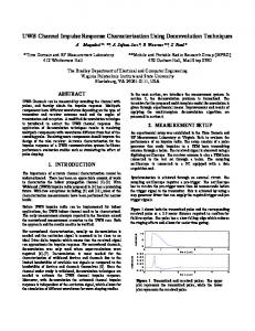
Fig. 4. Performance versus SNR and reduction factors for CM1 channel ensemble. The dashed line is associated with the full bandwidth non sparse restrictive system as in Fig. 1. It is SNR dependent and q independent. The solid lines describe CS schemes using OMP. entry only one of the q aliases is active, then this scheme gives direct access to M FFT entries. Proper DSP can then be employed, by FFT of the samples, demapping to the N length domain, accumulation and DS matched filtering in the frequency domain. Note that the ADC rate is q times less than the analog bandwidth (fN Y Q matched shaping filter is needed to suppress noise outside the Nyquist bandwidth) as in Fig. set L should be self-foldable, i.e. 3(d). The active L {m + M · i}q−1 = 1 for m = 0, . . . , M − 1. i=0 5. NUMERICAL RESULTS In order to support vast scalability, N was chosen to be 511, and 7 reduction factors were examined q = 1, . . . , 7. The high value of N allows even for the highest q = 7 to remain with enough projections M = 73. For reduction factors q which do not divide N , M was set to be the nearest integer value. The direct sequence aDS was chosen to be a trinary Ipatov sequence, and has 256 non zero elements. The number of repeated pilot symbols Np was set to 200. The shaping and matched filters are truncated sincs with 16 sidelobes (almost perfect low pass filters over 500 MHz). The continuous time line is modeled under 8 GHz grid, which is 16 times denser than a single Nyquist chip. On this 125 ps spaced tap line, 100 realizations of hch (t) were drawn according to CM1 statistics via a MATLAB code provided by [7], where random complex phase was employed to each of the multipath components. For each channel realization, a unified simulation run with Nyquist bandwidth lowpass as analog processing, full rate ADC, and serial to N blocks, piling Np symbols followed by FFT-N . On the output, for each of the abovementioned cases of choosing the active set, a discard operation of Lc values was perform in order to limit the total access to FFT coefficients. SNR is treated as Eb /N0 , which means that per SNR point all output power signals x(t) of any of the cases are gained to the same value. This
1969
means that the higher the reduction factor, the higher the spectral density (measured in [ mW/MHz]) on the active frequencies. The sparsity level K was set to 20, a typical value observed over channel realizations analysis. Fig. 4 shows performance dependancy on SNR and reduction factors. Intuitively, the direct random sampling and foldable sampling show better performances than low frequencies and the four bands samplng. The Nyquist scheme has superior performance, and for high SNRs the sub-Nyquist schemes are limited in their reconstruction capabilities. Alas, for q = 2 the energy capture degradation is indistinguishable for the distributed schems while keeping small negative impact on the RMSE. For q = 7 the effects are more prominent, yet a large portion of energy can still be recovered. 6. DISCUSSION This work considers applications of CS to UWB channel estimation. Hardware sampling schemes are described in two stages. First, analog acquisition using low rate ADCs is performed giving access to projections of the FFT domain. This is followed by sparse recovery methods to estimate the channel profile. The simplest low rate sampling method is narrowing the bandwidth, which gives poor results even for high SNR. Distributing the total bandwidth across a small number of bands does not help much. It is evident that highly distributed FFT coefficients give better reconstruction capabilities. Two such methods (direct sampling and foldable sampling) are analyzed. They both give similar modest degradation from the full sampling rate. For reduction of q = 2, almost all energy is captured and for q = 7 only 10% of energy is dropped. For high reduction factors one should consider the direct sampling since M analog branches is low while keeping noise low. For lower reduction factors the foldable sampling is advantageous, yet attention should be drawn to SNR issues such as dealing with the full band noise.
7. REFERENCES [1] M. Z. Win and R. A. Scholtz, “Ultra-wide bandwidth timehopping spread-spectrum impulse radio for wireless multipleaccess communications,” IEEE Transactions on Communications, vol. 48, no. 4, pp. 679–689, 2000. [2] “First report and order 02-48,” Federal Communications Commission, 2002. [3] A. Batra, “Multi-Band OFDM Physical Layer Proposal for IEEE 802.15 Task Group 3a,” doc.IEEE 802.15-03/268r3, 2004. [4] H. Nyquist, “Certain topics in telegraph transmission theory,” Trans. AIEE, vol. 47, no. 2, pp. 617–644, 2002. [5] H. Yu and S. Guo, “Compressed Sensing: Ultra-Wideband Channel Estimation Based on FIR Filtering Matrix,” 2012, Available: http://dx.doi.org/10.5772/48714. [6] M. Basaran, S. Erkucuk, and H.A. Cirpan, “The effect of channel models on compressed sensing based UWB channel estimation,” in 2011 IEEE International Conference on UltraWideband (ICUWB). IEEE, 2011, pp. 375–379. [7] A. F. Molisch, K. Balakrishnan, C.-C. Chong, S. Emami, A. Fort, J. Karedal, J. Kunisch, H. Schantz, U. Schuster, and K Siwiak, “IEEE 802.15. 4a channel model-final report,” IEEE P802, vol. 15, no. 04, pp. 0662, 2004. [8] A. F. Molisch, “Ultrawideband propagation channels-theory, measurement, and modeling,” IEEE Transactions on Vehicular Technology, vol. 54, no. 5, pp. 1528–1545, 2005. [9] D. L. Donoho, “Compressed sensing,” IEEE Transactions on Information Theory, vol. 52, no. 4, pp. 1289–1306, 2006. [10] E. J. Candès and T. Tao, “Near-optimal signal recovery from random projections: Universal encoding strategies?,” IEEE Transactions on Information Theory, vol. 52, no. 12, pp. 5406– 5425, 2006. [11] Y. C. Eldar, Sampling Theory: Beyond Bandlimited Systems, Cambridge University Press, in preparation. [12] E. J. Candès, J. Romberg, and T. Tao, “Robust uncertainty principles: Exact signal reconstruction from highly incomplete frequency information,” IEEE Transactions on Information Theory, vol. 52, no. 2, pp. 489–509, 2006. [13] Y. C. Pati, R. Rezaiifar, and P.S. Krishnaprasad, “Orthogonal matching pursuit: Recursive function approximation with applications to wavelet decomposition,” in 1993 Conference Record of The Twenty-Seventh Asilomar Conference on Signals, Systems and Computers. IEEE, 1993, pp. 40–44. [14] J. L. Paredes, G. R. Arce, and Z. Wang, “Ultra-Wideband Compressed Sensing: Channel Estimation,” IEEE Journal of Selected Topics in Signal Processing, vol. 1, no. 3, pp. 383–395, 2007. [15] E. Lagunas and M. Nájar, “Sparse channel estimation based on compressed sensing for ultra wideband systems,” in 2011 IEEE International Conference on Ultra-Wideband (ICUWB). IEEE, 2011, pp. 365–369. [16] Z. Rui and J. Lei, “Time and frequency domain receiver of UWB signal based on compressive,” in 2010 International Conference on Computer Application and System Modeling (ICCASM). IEEE, 2010, vol. 5, pp. V5–58 – V5–62.
1970
[17] Z. Wang, G. R. Arce, B. M. Sadler, J. L. Paredes, and X. Ma, “Compressed detection for pilot assisted ultra-wideband impulse radio,” in ICUWB 2007. IEEE International Conference on Ultra-Wideband. IEEE, 2007, pp. 393–398. [18] P. Zhang, Z. Hu, R. C. Qiu, and B. M. Sadler, “A compressed sensing based ultra-wideband communication system,” in ICC’09. IEEE International Conference on Communications. IEEE, 2009, pp. 1–5. [19] E. Baransky, G. Itzhak, I. Shmuel, N. Wagner, E. Shoshan, and Y. C. Eldar, “A sub-Nyquist radar prototype: Hardware and algorithms,” arXiv, 2012, Available: http://arxiv.org/ abs/1208.2515. [20] V.P. Ipatov, “Ternary sequences with ideal periodic autocorrelation properties,” Radio Engineering and Electronic Physics, vol. 24, pp. 75–79, 1979. [21] H.-J. Lee, D. Ha, and H.-S. Lee, “A frequency-domain approach for all-digital CMOS ultra wideband receivers,” in 2003 IEEE Conference on Ultra Wideband Systems and Technologies. IEEE, 2003, pp. 86–90. [22] M. Vetterli, P. Marziliano, and T. Blu, “Sampling signals with finite rate of innovation,” IEEE Transactions on Signal Processing, vol. 50, no. 6, pp. 1417–1428, 2002. [23] K. Gedalyahu, R. Tur, and Y. C. Eldar, “Multichannel sampling of pulse streams at the rate of innovation,” IEEE Transactions on Signal Processing, vol. 59, no. 4, pp. 1491–1504, 2011. [24] H. Sun, D. I. Laurenson, and J. S. Thompson, “Cooperative compressive spectrum sensing by sub-Nyquist sampling,” in 2009 First UK-India International Workshop on Cognitive Wireless Systems (UKIWCWS). IEEE, 2009, pp. 1–5.