under the hood of Honda Accord. Measurements are made within the vehicle and the vehicle engine compartment. But. 5For one thing, ISI can be reduced due ...
Channel Reciprocity and Time-Reversed Propagation for Ultra-Wideband Communications Robert C. Qiu, Chenming (Jim) Zhou, John Qiang Zhang, Nan Guo Department of Electrical and Computer Engineering Center for Manufacturing Research Tennessee Technological University Cookeville, TN 338505 Email: {rqiu, czhou21, qzhang21, nguo}@tntech.edu
Abstract— This paper is the first paper of an new effort to understand UWB communications and sensor networking in RF harsh environments. Channel reciprocity and time reversed propagation are studied, using an intra-vehicle environment. Communications using time reversal is also investigated.
I. I NTRODUCTION This paper is the first paper of an new effort to understand ultra-wide bandwidth (UWB) communications and sensor networking in RF harsh environments such as indoors, mines, tunnels, intra-vehicles, ships, etc. Our goal is to achieve system performance gains for range extension or higher data rate. Time reversed propagation and transmission is the first scheme under the novel system framework—of taking full advantage of the long-term channel symmetry. UWB communications has been studied in the pioneering work of Win and Scholtz [1] and others [2], [3] , [4]. For UWB sensor networks, a feasible system structure is to use energy detection that suffers from performance degradation caused by rich multipath. As a result, time reversal transmission—see [5] for a review—is used to collect multipath energy and overcome inter-symbol-interference (ISI). Although time reversal proves to be promising for UWB systems, some basic questions are still open. If advanced system concepts are explored to cope with co-channel and multiuser interference in a UWB-MIMO (Multiple-Input Multiple Output) context, more fundamental work needs to be carried out. One such problem is channel reciprocity and its significance to system concepts. Channel State Information (CSI) at the transmitter is critical to future generation wireless communication. CSI at the transmitter provides the flexibility to shift the signal processing to wherever it is desired—for UWB systems, the receiver complexity is minimized for easy implementation in the current semiconductor industry. This topic has been systematically investigated in narrowband systems. In UWB systems, this principle is rarely studied. Due to channel reciprocity, the CSI can be used to preprocess the transmitted data and to control the scheduling of multiple users signals in the space-time domain. The key challenge is to make CSI of sufficient quality instantaneously available at the transmitter. The fundamental problem at hand is the question of whether channel reciprocity holds at the baseband. Channel reciprocity holds at the antennas—but
usually gets lost in the baseband for narrowband systems [7]. From CSI point of view, time-division duplexing (TDD) is preferred to frequency-division duplexing (FDD). UWB uses a TDD transmission. The challenge of TDD is to provide channel reciprocity at the baseband inputs and outputs of the communication system. To answer the above fundamental question, a UWB propagation measurement is made using the time domain channel sounder1 . A basic difference has been found between the UWB systems and the narrowband systems, with respect to the principle of channel reciprocity—called symmetry below. It is found that channel reciprocity holds at the baseband for UWB systems—in contrast to the narrowband systems. In the harsh environment within the engine compartment, forward link and reverse link are highly symmetric and stationary for the whole measurement duration2 of 40 minutes! One explanation for the above amazing result is at hand. RF non-reciprocity is typically caused by different I/Q mixers, amplifiers and path lengths in the separate RF chains at the transmitter and receiver. For the pulse-based UWB systems, no carrier is used—this may be the reason. Once channel reciprocity at the baseband is established, this principle can be used for novel system concepts. Since the channel symmetry holds for such a long period, the initial learning for the sufficiently accurate CSI is negligible3 . As a result, the focus of the system is on the transmitter pre-coding—to take full advantage of the long-term channel symmetry. Fortunately, for the UWB sensor networks of IEEE 802.15.4a [8], a cluster of low-complexity sensor nodes (SNs) conveys information to several access points (APs), some of which may be connected to a wireless backbone network. Aps—may equipped with multiple antennas—are expected to deal with high aggregate traffic and strong multiple access interference. Therefore, the broadcast channel—one point to many points—is of our interest. Time reversed transmission is the simplest schemes in the novel system framework. Although time reversal has been 1 This
channel sounder is in part funded by ARO through a DURIP grant. longer time will be measured in the future. The engine is operating during measurement. 3 The perfect CSI can be assumed without loss of practical significance. 2A
studied in our team for the last several years—e.g. see [5], it is the recent new understanding that puts time reversal as one of the novel schemes under the above unified view. Other advanced transmitter precoding algorithms [9], such as zeroforcing spatial filtering and triangularization spatial prefiltering with dirty-paper coding (DPC), can be explored under the context of UWB systems. A work [10], where an indoor laboratory environment is studied, and another one [6], are related to this paper. II. S YSTEM M ODEL The goal is to explore the framework of using non-coherent energy detection in the receiver while using advanced spatiotemporal precoding at the transmitter. This structure is detailed in [5]. The prerequite for this structure is channel reciprocity that holds for a reasonably long period of time. What we seek is channel reciprocity at the baseband, which will be shown by the experimental waveforms below. Consider a linear pulse amplitude modulation (PAM) as an example to illustrate the significance of the long-term reciprocity in the system level. A PAM signal at the transmitter can be expressed as ∞ ∞ X X An δ(t − tn ) (1) An g(t − tn ) = g(t) ⊗ x(t) = n=−∞
n=−∞
where g(t) represents the shape of the individual baseband pulses4 , An are information symbols, and the occurrence time tn = nTs are the sampling instants nTs . The Ts is the sample duration, and ⊗ denotes the operation of convolution. Let us consider transmission in the down link (or forward link). A UWB channel is modeled as a linear-timeinvariant (LTI) system whose impulse response is represented by hdown (t). After transmission through the channel, the received waveforms at the receiver ∞ X An δ(t−tn )+I(t)+n(t) (2) r(t) = g(t)⊗hdown (t)⊗
If perfect channel reciprocity holds at the baseband, then hdown (t) = hup (t) = h(t)
(5)
(Refer to Fig.(3) for such measured waveforms.) Thus, it follows from Eq. (4) and Eq. (5) that r(t) = g(t) ⊗ Rhh (t) ⊗
∞ X
An δ(t − tn ) + I(t) + n(t) (6)
n=−∞
where Rhh (t) = h(t)×h(−t) is the autocorrelation of the CIR. The Rhh (t) has the desirable properties5 we are seeking to be combined with the low-complexity energy detection. (See Fig. 5 for its measured waveforms.) Detection of r(t) is critical to UWB communications. With dirty-paper-precoding at the transmitter, it is possible to remove interference I(t), such as ISI, co-channel, and multiuser. It follows from Eq. (6) that r(t) = g(t) ⊗ Rhh (t) ⊗
∞ X
An δ(t − tn ) + n(t)
(7)
n=−∞
The detection problem of (7) is standard, and optimum using maximum likelihood sequential detection (MLSE) [2]. However, it is infeasible for the current industry to implement MLSE for UWB systems. Rather, energy-detection is adopted in IEEE 802.15.4a for UWB sensors. It is interesting to keep the low-complexity of the receiver, but use advanced precoding algorithms at the transmitter—fully exploiting the long-term channel reciprocity. Performance simulation is carried out using on-off keying (OOK) modulation with non-coherent energy detection. OOK can be viewed as a special case of PAM. For system details, see [11]. Bit Error Rate (BER) is obtained using a data rate of 50 Mbps. The pulse waveform used is the template shown in Fig. 3(b). The measured waveforms at the receiver are used. III. T IME -D OMAIN C HANNEL S OUNDING
To confirm the assumptions made behind the above system model, experimental measurements must be performed. One where I(t) and n(t) are the interference and the noise introgoal is to understand the waveform properties of Rhh (t). duced by the channel. We are, in particular, interested in intra-vehicle sensors. See In a TDD sytstem, the channel impulse response (CIR), Fig.1 for a picture. A template waveform is measured when hup (t), is learned from the uplink (or reverse link). Without the distance between the transmitter antenna and the receiver loss of practical significance, the transmitter is assumed to antenna is one (1) meter—See Fig. 3(b) for this waveform. know hup (t) perfectly. Rather than using the signal in Eq. Antenna near-field effects are removed this way. Antennas are (1) using the pulse waveform g(t), we precode g(t) with located deeply in the engine such that only non-line-of-sight a waveform W (t), exploiting the CIR information. After (NLOS) pulses are present. precoding, the new symbol waveform is expressed as W (t) The experimental setup is shown in Fig. 2. The sounding p(t) = g(t) ⊗ W (t) (3) pulse has a 10-dB bandwidth of 800 MHz-2.5 GHz. A The simplest scheme is to choose time reversal, i.e., W (t) = signal generator is used to trigger the pulser. Omni-directional hup (−t). As a result, the received signal after time reversed antennas are used in both of transmitter and receiver. A digital sampling oscilloscope (DSO) is used to capture short UWB propagation can be rewritten from Eq. (2) as pulses. For more details, see [10]. The experiment is conducted ∞ X An δ(t−tn )+I(t)+n(t) under the hood of Honda Accord. Measurements are made r(t) = g(t)⊗hdown (t)⊗hup (−t)⊗ within the vehicle and the vehicle engine compartment. But n=−∞ (4) n=−∞
4 There
is no carrier used.
5 For one thing, ISI can be reduced due to the sharp peak in the center of the function.
Waveform forward link reverse link
Amplitude(Volt)
0.02 0.01 0 −0.01 −0.02 0
10
20
30
40
50
Time(ns) Waveform forward link reverse link
Amplitude(Volt)
0.02 0.01 0 −0.01 −0.02 2
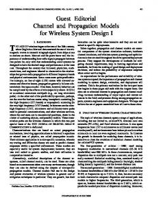
Fig. 1.
UWB pulse propagation within the engine compartment.
4
6
(a)
8
10 Time(ns)
12
14
16
0.8 0.6
Amplitude(V)
0.4 0.2 0 −0.2 −0.4 −0.6
(b)
−0.8 0
Fig. 3. Fig. 2.
5
10 Time(ns)
15
20
Channel reciprocity in the engine compartment.
Experimental Setup.
only the latter case are presented due to space limit. Similar results are obtained. IV. R ESULTS The transceiver antennas are put in the engine compartment. The positions of antenna A and G are labelled in Fig. 1. Fig. 3 illustrates channel reciprocity between channel A-G and G-A. The forward link is defined as the link from antenna A to antenna G. Two received waveforms measured in the forward and reverse links almost coincide with each other. The correlation between these two waveforms is as high as about 0.98. In Fig. 3(a), the forward and reverse link waveforms are measured under the same conditions, except that the DSO (excluding antenna and cable) and the pulser (excluding antenna and cable) are switched. In other words, antenna and cable are treated as part of the channel. The bottom plot of Fig. 3 (a) shows a closer look of the above plot of Fig. 3 (a). The waveforms shown in Fig. 3(a) are measured while the engine is on. The result is almost the same when the engine is off. The similar result can be observed when the antenna positions are changed. Experiments are used to investigate the instantaneousness of channel reciprocity. The transmitter antenna is located in the position A in Fig. 1. The receiver antenna6 is located in the position G in Fig. 1. Forty (40) received waveforms are recorded at every one minute for a duration of 40 minutes. For each waveform, the signal lasts 50ns, compared with the template waveform in Fig. 3(b). The 40 waveforms are plotted in Fig. 4. The correlation between any two waveforms is greater than 0.99—These waveforms are almost identical within 40 minutes! 6 Points
E, F, H in Fig. 1 are also measured and similar results are obtained.
Fig. 4.
Channel Reciprocity holds for a long period of time (40 minutes).
Fig. 5(a) shows the original waveform without time reversal—This waveform is also the waveform captured directly by the DSO. It can be seen in Fig. 5(a) that there is no LOS and the energy of the received signal is distributed among a lot of multipath components, compared with the template waveform in Fig. 3(b). How to collect received multipath energy is a challenging for UWB systems. One of the techniques used to deal with this problem is time reversal (TR). Fig. 5(b) shows the received waveform with TR precoding at the transmitter side. Assuming channel is reciprocal and static, which has been confirmed above, the time reversed version of the received waveform (shown in Fig. 5(a)) can be used as TR precoding. By doing this, a short peak is then observed in the received waveform after time-reversed propagation. This observation hints at the usage of the low complexity receiver like square law detector. The peak of the received signal can be enhanced, without requiring extra transmitted power, by employing multiple antennas at the transmitter side. Fig. 5(c) shows the received waveform, assuming a four by one (4x1) multiple input single output (MISO)-TR is employed. Transmitter antennas are located at
Amplitutde (V)
0 Receiving Waveform
−0.02 0
10
20
30
40
Time (ns)
50
60
100
120
Amplitutde (V)
0.2 Waveform: TR
0.1 0
−0.1 0
20
40
60
0.4
Amplitutde (V)
80
Time (ns)
Waveform: MISO−TR
0.2 0
−0.2 0
20
40
60
80
Time (ns)
100
two (2) dBs is obtained by using time reversal, due to moderate multipath. More powerful precoding schemes such as zeroforcing and dirty-paper-coding must be used to deal with ISI and other interference. The intra-vehicle environment has fewer multipath components than indoors—but is more static. One reason is that the distance of the former is much shorter. Pulse waveform distortion is more obvious than the latter: antenna near-field effects are present in the intra-vehicle environment. These experimental studies suggest that the transmitter-centric system paradigm is efficient and promising.
120
ACKNOWLEDGMENT Fig. 5.
Waveforms received at the receiver after time reversed propagation. 0
10
−1
10
without time reversal −2
BER
10
4x1 MISO time reversal
−3
10
We thank Drs. Santanu K. Das, Brian Sadler, and Robert Ulman for helpful discussions. This work is funded by the Office of Naval Research through a grant (N000140710529), National Science Foundation through a grant (ECS-0622125), the Army Research Laboratory, and the Army Research Office through a STIR grant (W911NF-05-1-0468), and a DURIP grant (W911NF-05-1-0111). The author is sponsored by ONR Summer Faculty program to work at Naval Research Laboratory in the summer of 2006 to study time reversal for underwater communications.
−4
10
R EFERENCES 8
9
10
11
12
13
14
15
Eb/No
Fig. 6. Bit error rate of the system using time reversal and energy detection.
points A, B, C, D in Fig. 1. As shown in Fig. 5(c), the amplitude of the peak signal is almost doubled, compared to that of single input single output (SISO)-TR shown in Fig. 5(b). While increasing the peak power, MISO-TR introduce weaker side-lobes. In Fig. 6, ISI is introduced and Eb /N0 is the per-bit SNR at the received side. Note that if the per-bit SNR is measured at the transmitter side, an M ×1 MISO system would approximately have an additional gain of 10log10 M dB over a SISO system. From this result we can conclude that time reversal can effectively reduce ISI impact. It can be expected that the MISO system performance would be improved further, as the number of antenna elements increases. V. S UMMARY Experiments are made to investigate channel reciprocity and its instantaneousness in the intra-vehicle environment. This investigation helps to understand applications such as shipboard and inside-ship communications. It is found that the channel is highly reciprocal at the baseband—very different from the narrowband channel. Further, channel reciprocity holds for the whole measurement duration of forty minutes. Time reversal is used to reduce the complexity of the receiver structure. As an illustration, a system concept of using time reversal transmission at the transmitter and energy detection at the receiver is evaluated for its BER. Only a moderate gain of
[1] M. Z. Win and R. A. Scholtz, “Ultra-wide Bandwidth Time-hopping Spread-spectrum Impulse Radio for Wireless Multiple-access Communications,” IEEE Trans. Commun., vol.48, no. 4, pp.679-691, April 2000. [2] R. C. Qiu, H. Liu, and X. Shen, “Ultra-Wideband for Multiple Access,” IEEE Commun. Mag., Vol. 43, No. 2, pp. 80-87, Feb. 20057 . [3] R. C. Qiu, R. Scholtz, and X. Shen, “Ultra-Wideband Wireless Communications– A New Horizon,” Editorial on Special Session on UWB, IEEE Trans. Veh. Technol., Vol. 54, No. 5, Sept. 2005. [4] X. Shen, M. Guizani, H. H. Chen, R. Qiu, A. F. Molisch, “Ultra-wideband Wireless Communications,” Editorial on Special Issue on UWB, IEEE J. Select. Areas Commun.,Vol. 24, 2nd Quarter 2006. [5] R. C. Qiu, “A Theory of Time-Reversed Impulse Multiple-Input MultipleOutput (MIMO) for Ultra-Wideband (UWB) Communications (invited paper),” 2006 Int’l Conf. UWB, Waltham, MA, Oct. 2006. [6] J. Li and T. Talty, “Channel Charaterization for Ultra-Wideband IntraVehicle Sensor Networks,” IEEE MILCOM, Washington, D. C., Oct., 2006. [7] G. Fettweis, E. Zimmerman, V. Jungnickel, E. A. Jorswieck, “Challengs in Future Short Range Wireless Systems,” IEEE Veh. Tech. Mag., Vol. 1, No. 2, pp.24-31, June 2006. [8] F. Althaus, F. Chin, J. Kunisch, J. Pamp, B. Radunovic, U. G. Schuster, F. Trosch, H. L. Truong, M. Weisenhorn, and R. Zetik, “A Comprehensive Investigation of UWB Sensor Networks for Industrial Applications,” 15th IST Mobile & Wireless Communications Summit 2006, Mykonos, Greece, June 2006. [9] D.Samardzija, N. Mandayam, D. Chizhik, “Adaptive Transmitter Optimization in Multiuser Multipleantenna Systems: Theoretical Limits, Effect of Delays, and Performance Enhancements,” EURASIP J. Wireless Commun. Networking, Vol. 3, pp. 298-307, 2005. [10] R. C. Qiu, C. Zhou, N. Guo, J. Q. Zhang, “Time Reversal with MISO for Ultra-Wideband Communications: Experimental Results”, IEEE Antenna and Wireless Propagation Letters, April 2006. [11] N. Guo, J. Q. Zhang, R. C. Qiu, S. Mo, “UWB MISO Time Reversal With Energy Detector Receiver Over ISI Channels”, IEEE Consumer Commun. and Networking Conf., Las Vegas, Nevada, Jan. 11-13 2007.
7 All the cited papers from R. C. Qiu and his team are available at http://iweb.tntech.edu/rqiu/.