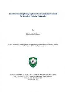
1. 1. Introduction. 2. IEEE Recommended Practice for Architecture. Modeling. 3.
Architecture Description Language: the UML. 4. The Rational Unified Process ...
Chap 1. Introduction to Software Architecture 1. Introduction 2. IEEE Recommended Practice for Architecture Modeling 3. Architecture Description Language: the UML 4. The Rational Unified Process (RUP)
1
1. Introduction Preamble “Conventional wisdom has been to use terms like ‘software architecture’, ‘software architectural design’, or ‘coarse-grained design’ for the high-level structural subdivision of a system, and ‘design’ or ‘detailed design’ for more detailed planning… we denote the whole activity of constructing a software system as ‘software design’ and the resulting artifacts as ‘software architecture’.” “Many developers nowadays prefer the term ‘software architecture’ to ‘software design’ for denoting all the artifacts that result from design activities.” “In doing so, they want to express the fact that they do not just decompose the functionality of a system into a set of cooperating components, but rather that they construct a software architecture… They no longer agree that high-level design decisions can be made independently of lower-level decisions.” From “Pattern-Oriented Software Architecture, A System of Patterns” By F. Buschmann, R. Meunier, H. Rohnert, P. Sommerlad, M. Stal 2
Software Architecture as a Design Plan �Software architecture provides a design plan, a blueprint of a system, an abstraction to help manage the complexity of a system, and also a communication medium between stakeholders. �Critical factor for a product’s success: good software architecture that is understood by the stakeholders and by the developers. �Structural plan that describes the elements of the system, how they fit together, and how they work together to fulfill the system’s requirements. •Used to negotiate system requirements, and to set expectations with customers, marketing and management personnel. •Used as a blueprint during the development process •Guides the implementation tasks, including detailed design, coding, integration, and testing.
3
�Comes after the domain analysis, requirements analysis, and risk analysis, and before detailed design, coding, integration and testing. requirements, desired qualities Domain Analysis, Requirements Analysis, Risk Analysis
hardware architecture Software Architecture Design
Hardware Architecture Design modifications to hardware architecture
modifications to requirements software architecture
implementation constraints Detailed Design, Coding, Integration, Testing
feed forward feedback
�Key inputs to software architecture design: •The requirements produced by the analysis tasks •The hardware architecture (the software architect in turn provides requirements to the system architect, who configures the hardware architecture)
4
2. IEEE Recommended Practice �Unfortunately, software architecture is still an emerging discipline within software engineering; limitations: •lack of standardized ways to represent architecture •lack of analysis methods to predict whether an architecture will result in an implementation that meets the requirements.
�So far, the most advanced efforts towards the development of a standard have been made by the IEEE Working Group on Software Architecture, giving rise to the IEEE Recommended Practice for Software Architecture Development. �The IEEE Recommended practice for Software Architecture Development: ÷Define a conceptual framework for architecture development. ÷Goal: evolve into a standard 5
Conceptual Framework -Every system has an inherent architecture. ÷The concrete document that is associated with the architecture actually provides a specific description of the architecture, also referred to as an architectural description (AD).
-An architectural description consists of a collection of views: ÷each view describes one or more concerns involved in the system.
-A viewpoint defines the modeling and analysis techniques and conventions used to create a view that describes the concerns addressed by the viewpoint. ÷Viewpoint definitions may be provided either as starting point of the AD or by reusing existing viewpoints also referred to as library viewpoints. ÷A view may be associated to exactly one viewpoint within the same AD, and consists of one or more architectural models.
-Every stakeholder's concerns must be addressed by at least one viewpoint ÷Viewpoints may be overlapping, in which case potential inconsistencies must be analyzed and recorded.
6
Examples: ÷Viewpoints and Views in Structured Analysis (SA)
Note: -DFD: Data Flow Diagram -ERD: Entity-Relation Diagram -STD: State Transition Diagram
÷Viewpoints and Views in Object-Oriented Analysis (OOA)
7
Conceptual Model of Architectural Description
8
Conformance An architecture description that conforms to the IEEE guidelines encompasses at least six different kinds of information: -Architectural documentation ÷provides reference and overview information about the AD: version number, issue date, issuing organization, summary, scope and context of the AD etc.
-Identification of system stakeholders and their concerns. -Specification of the viewpoints selected to represent the AD and the motivation for the choice of these viewpoints. -Architectural views derived from the viewpoints. A view is associated to exactly one viewpoint, to which it must conform. -Potential inconsistencies among the views and the underlying models must be analyzed, recorded and if necessary resolved. -The rationale behind the architectural concepts selected.
9
3. Architect. Description Language: the UML
UML 2.0
-The UML is a language for visualizing, specifying, constructing and UML 1.4 documenting the artifacts of a software-intensive system. -Creating the UML UML 1.3 OMG Acceptance, Nov 1997
UML 1.1
Final submission to OMG, Sep ‘97 public feedback
First submission to OMG, Jan ´97
UML 1.0
UML partners
UML 0.9
Web - June ´96
OOPSLA ´95
Other methods
Unified Method 0.8
Booch method
OMT
OOSE 10
Views, Models, and Diagrams -A diagram is a model in a view; a view consists of one or more models -A view is an instance of a viewpoint for a particular system: •presented from the aspect of particular stakeholders •provides a partial representation of the system •is semantically consistent with other views
-In the UML, there are thirteen standard diagrams: •Structure diagrams: class, object, component, deployment, composite structure, package diagrams •Behavior diagrams: activity, state machine, use case, and interaction diagrams - Interaction diagrams: sequence, communication, interaction overview, and timing diagrams
Use Case Use Case Interaction Overview Diagrams Diagrams Diagrams Use UseCase Case Communication Diagrams Diagrams Diagrams Use Case Use Case Sequence Diagrams Diagrams Diagrams Scenario Scenario Use Case Diagrams Diagrams Diagrams
Use UseCase Case Timing Diagrams Diagrams Diagrams
State State Class Diagrams Diagrams Diagrams
Use Case Use Case Package Diagrams Diagrams Diagrams
State State Component Diagrams Diagrams Diagrams
Models Scenario Scenario Statechart Diagrams Diagrams Diagrams
Activity Diagrams
Use Case Use Case Composite Structure Diagrams Diagrams Diagrams State State Object Diagrams Diagrams Diagrams
Component Component Deployment Diagrams Diagrams
Diagrams
11
4. The Rational Unified Process (RUP) Process -Software engineering process: •A set of partially ordered steps intended to reach a goal, which is to build a software product or to enhance an existing one.
The Rational Unified Process -Extensive set of guidelines supporting an iterative and incremental life cycle and focusing on requirements analysis and design. •Development proceeds as a series of iterations that evolve into the final system. •Each iteration consists of one or more of the following steps: requirements capture, analysis, design, implementation, and test.
12
•Risk-mitigating process: technical risks are assessed and prioritized early in the life cycle and are revised during each iteration. •Releases are scheduled to ensure that the highest risks are tackled first.
Initial risks Initial project scope
Revise project plan
Define iteration to address the highest risks
Iteration N Revise risk assessment
Plan and develop the iteration Assess the iteration Risks eliminated
13
Phases of the Rational Unified Process -Structured along two dimensions: •time division of the life cycle into phases and iterations •process components consisting of the production of a specific set of artifacts with well-defined activities
-Each activity of the process component dimension typically is applied to each phase of time-based dimension, but at a varying degree dependent upon the specific phase.
14
Lifecycle Phases (Time Dimension)
Inception
Elaboration
Construction
Transition
time
•
Inception
Define the scope of the project and develop business case
•
Elaboration
Plan project, specify features, and baseline the architecture
•
Construction
Build the product
÷ Transition
Transition the product to its users 15
Phases and Iterations (Process Component Dimension)
Inception
Prelim Iteration
...
Elaboration
Arch Iteration
...
Construction
Dev Iteration
Dev Iteration
Transition
...
Releasecomponent Release Release Releaseincludes: Release �The process dimension
Trans Iteration
Release
Release
...
Release
• Requirements capture: a narration of what the system should do • Analysis and design: a description of how the system will be realized in the implementation phase • Implementation: the production of the code that will result in an executable system • Test: the verification of the entire system
16
Unified Process Structure
Phases Process Workflows
Inception Elaboration
Construction
Transition
Business Modeling Requirements Analysis & Design Implementation Test Deployment
Supporting Workflows Configuration Mgmt Management Environment Preliminary Iteration(s)
Iter. #1
Iter. #2
Iter. #n
Iter. Iter. #n+1 #n+2
Iter. #m
Iter. #m+1
Iterations 17
Architecture Modeling The “4+1” Views of Architecture -RUP advocates the use of multiple perspectives to describe the various concerns. RUP suggests a five views approach:
Logical View Classes, interfaces, collaborations
Process View
Process,Threads
Use cases
Use Case View Implementation View
Deployment View
Source, binary, executable components
Organization Package, subsystem
Nodes
Dynamics Interaction, State machine
18
-Use case view:
÷consists of a set of key use cases or scenarios, which guide the design of the architecture during the inception and elaboration phases and are used later to validate the other views.
-Logical view: ÷addresses the functional requirements of the system; provides an abstraction of the design model and defines main design subsystems and classes.
-Process view: ÷defines the system’s concurrency and synchronization mechanisms at run-time (tasks, threads, processes etc.).
-Deployment view: ÷defines the hardware topology on which the system is executed.
-Implementation view: ÷defines the parts used to assemble and release the physical system (source code, data files, executables etc.). 19
Simple Monolithic App. Use Case View •Use case diagrams
Logical View •Class diagrams •Interaction diagrams
Process View •None required
Implementation View •None required
Deployment View •None required
Complex Distributed App. Use Case View •Use case diagrams •Activity diagrams
Logical View •Class diagrams •Interaction diagrams •Statechart diagrams
Process View •Class diagrams •Interaction diagrams
Implementation View •Component diagrams
Deployment View •Deployment diagrams 20