A machine, which performs the material removing operation with tools, to produce desired ... Lathes are generally considered to be the oldest machine tools.
CHAPTER
11
Introduction to Machine Tools 11.1
INTRODUCTION
A machine, which performs the material removing operation with tools, to produce desired shape and size of the work piece, is known as machine tool. The various types of machine tools commonly used in manufacturing are: Lathe, Shaper, Planer, Drilling machine, Grinding machine, Milling machine, Sawing machine and there may still be several machines to serve special purposes.
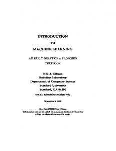
11.2 LATHES AND LATHE OPERATIONS Lathes are generally considered to be the oldest machine tools. Although woodworking lathes were first developed during the period 1000-1 B.C., metal working lathes with lead screws were not built until the late-1700s. Henry Maudsley developed the sliding carriage in 18th century, after that a lot of development has taken place and lathes are now available in various sizes and shapes. The most common lathe, shown in Fig. 11.1, was originally called an engine lathe because it was the first machine to be driven by Watt’s steam engine. The lathe is the father of all machine tools. It is the most important machine used in workshop. In early days lathes were driven by line shaft but now they are equipped with individual electric motors. However, various types of automation can be added to improve efficiency of the lathe in modern industry. The function of lathe is to remove the material by rotating the work piece against a single point cutting tool. The material is removed from surface of workpiece in form of a chip. In its operation the lathe holds a rotating piece of material between two rigid supports called centre, or in some other device such as a chuck or face plate. Generally two methods are employed for revolving the work. The first one is by belt drive and the second by wheels which are revolved either by a belt or by an electric motor. A cylindrical workpiece held in a chuck and tool removing material in form of a chip is shown in Fig. 11.2.
223
224
MANUFACTURING SCIENCE
Just as various speeds are required to revolve the work, the cutting tool must also move along at different speeds. This movement is known as the feed.
Fig. 11.1
Parts of lathe
Fig. 11.2 Cutting on lathe
INTRODUCTION TO MACHINE TOOLS
225
11.2.1 Classification of Lathes Lathe are classified in many ways with respect to size, design, method of drive and purpose. Lathes can be classified as: 1. 2. 3. 4. 5. 6. 7.
Speed lathe Engine or centre lathe Bench lathe Tool room lathe Capstan and turret lathe Automatic lathes Special purpose lathe
11.2.2 Principal Parts of the Lathe Lathes are equipped with a variety of components and accessories. The principal parts of the lathes are: 1. Bed: The bed supports all the other major components of the lathe. It is the base or foundation of the lathe. Beds have a large mass and are built rigidly, usually from gray cast iron. The top portion of the bed has two guide ways, with various crosssection, that are hardened and machined accurately for wear resistance. These guideways are of two types—wide flat guideways and inverted V-guideways. 2. Headstock: It is permanently fastened on the innerways at the left side of the bed and equipped with moter, pulleys and V-belts that supply power to the spindle at various rotational speeds. The speeds can be set through manually controlled selectors. The headstock is equipped with a set of gears, and some have various drives to provide a continuously variable speed range to the spindle. Headstock has a hollow spindle to which work-holding devices, such as chucks and collets are attached. A live centre and sleeve, a face plate can be fitted to the spindle nose to hold and drive the work as shown in Fig. 11.1. Or a chuck may be placed on the spindle which has threaded end corresponding to internal threads on chuck. 3. Tailstock: This is a counter part of head stock. It is situated at the right end of the bed, and can slide along the guide ways and be clamped at any position. It supports the other end of the workpiece. It is equipped with centre that may be fixed (dead centre), or it may be free to revolve with the workpiece (live centre). The function of the tailstock is to provide a support to the end of the work, usually a shaft and also to feed a drill towards the work when boring or making a hole. The use of a dead centre allows a minimum of play, and it is possible to obtain more accurate work than when rotating upon live centre. A job of small length may not be supported at the tail stock as shown in Fig. 11.2. Tailstock and live centre are shown in Fig. 11.3.
226
MANUFACTURING SCIENCE
4. Carriage: The carriage is a moving part that slides over the way between the headstock and the tailstock and consists of an assembly of the cross-slide, tool post, and apron. The cutting tool is mounted on the tool post usually with a compound rest that swivels for tool positioning and adjustment. The cross-slide moves radially in and out, thus controlling the radial position of the cutting tool, as in facing operations. This motion provides depth of cut when turning a cylinder. The apron is equipped with mechanism for both manual and mechanized movement of the carriage and the cross-slide by means of the lead screw. 5. Feed Rod: The feed rod is powered by a set of gears from the headstock. It rotates during operation of the lathe and provides movement to the carriage and cross-slide by means of gears, a friction clutch and a keyway along the length of rod. 6. Lead Screw: The lead screw is used for cutting threads. The motion from the spindle motor is transmitted to the carriage through a lead screw. Engagement of the lead screw with the carriage is through the use of a half nut. Though the lead screw can be used for feeding the cutting tool in a direction parallel to the axis of rotation, many a times, a separate feed rod is provided for this function. The main reason is that the lead screw is more accurate and is sparingly used only for thread cutting, such that it maintains its accuracy.
Fig. 11.3 Tailstock and live centre
11.2.3 Lathe Accessories Work-holding devices are very important in machine tools and machining operations. The devices, which are used for holding and supporting the work and the tool on the lathe are called the lathe accessories. In a lathe machine, one end of the work price is clamped on the spindle by means of a chuck, collet, face plate, or mandrel.
INTRODUCTION TO MACHINE TOOLS
227
1. Chuck: A chuck provides the best and simplest method of holding and rotating work which is not suitable for mounting between the centres owing to its short length or large diameter as shown in Fig. 11.2. A chuck is usually equipped with three or four jaws. Three-Jaw chucks generally have a gear-scroll design that makes the jaws self-centering and hence are used for round work pieces, such as circular bar, pipes and tubing. Whereas the four jaw chucks have jaws that can be moved and adjusted independently of each other and thus can be used for out of centre cylinders, square or rectangular or odd-shaped work pieces. Chucks are available in various design and sizes. The device comprises a circular body with slots in which slide the jaws to grip the work, these jaws being made of tough steel with three steps on each to accommodate various diameters of work. The selection of chuck depends on the type and speed of operation, workpiece size, production and accuracy requirements and the jaw forces required. Chuck jaws are actuated manually with a chuck wrench or they may be power actuated. Since it takes longer to operate them, manually actuated chucks are generally used for tool room and limited production units. 2. Centres: The lathe centre is a hardened steel device with a taper shank on one end and a sixty degree taper ending in a point at the other end. Owing to the high speeds of work revolution, the fixed type of loose-head centre would be rapidly destroyed, so a live center must be fitted on a bearing to revolve with the work as shown in Fig. 11.3. 3. Face Plates: Face plates are used for clamping irregularly shaped work pieces. The plates are round and have serval slots and holes through which the work piece is bolted or clamped for machining purposes. 4. Mandrels: Mandrels are placed inside hollow work pieces and are used to hold workpieces that require machining on both end and on their cylindrical surfaces. This is an accurately ground cylindrical bar, made in various diameters and lengths as shown in Fig. 11.4. A mandrel of suitable diameter can be driven with sufficient force into the bore of the work to withstand the cutting action without slipping when the mandrel is mounted in between lathes centres. The accuracy of the work depends on the mandrel running true between the lathe centre.
Fig. 11.4
Various types of mandrels to hold Work pieces for turning. These mandrels are usually mounted between centers on a lathe. Note that in (a) both the cylindrical as well as the end faces of the work piece can be machined, whereas in (b) and (c) only the cylindrical surfaces can be machined.
228
MANUFACTURING SCIENCE
5. Carrier: When a square bar is revolving between the centres, a carrier must be clamped on it and engaged with a projecting dog on the catch plate. Three types of lathe carriers are shown in Fig. 11.5. There are several types of carrier, which are being made by drop forging with various sizes of holes to accommodate different bar diameters. Hardened steel screws with square heads are provided to tighten on to the bar as shown in Fig. 11.5. It has a wide range of features to prevent vibration, while on intermittent cutting and also available to prevent shock and inaccurate work.
Fig. 11.5 Types of lathe carriers. These are generally drop-forgings with holes of varying sizes to take bars of different diameters
6. Collet: A collet is basically a longitudinally split taper bushing. The work piece is placed inside the collet, and the collet is pulled or pushed into the spindle by mechanical means as shown in Fig. 11.6. Collets are used for round workpieces as well as other shapes such as square, hexagonal, etc. The advantage of using a collet over a three jaw chuck or four jaw chuck is that the collet grips nearly all the circumference of the part, and is particularly suited for parts with small cross-section.
Fig. 11.6 (a) Schematic illustrations of a draw-in type collet. The Work piece is placed in the collet hole, and the conical surfaces the collet are forced inward by pulling it with a draw bar into the sleeve. (b) A push-out type collet
11.2.4 Size and Specifications of a Lathe A lathe is usually specified by its swing, that is, the maximum diameter of the workpiece that can be machined, by the maximum distance between the head stock and tail stock centers and by length of the bed.
INTRODUCTION TO MACHINE TOOLS
229
The size of a lathe is also determined by: 1. Height of centres from bed. 2. Maximum swing over bed. 3. Maximum swing over carriage. 4. Length of bed. 5. Maximum length of the work that can by accommodated between the lathe centres. 6. Maximum diameter of the work that can be accommodated in the gap for a gap bed lathe. 7. The length, width, and depth of bed. 8. The number of feeds and the number and range of spindle speeds. 9. The lead screw diameter. 10. The back gear ratio. 11. The number and range of metric threads that can be cut. 12. The power rating of electric motor. 13. The tailstock spindle travel.
11.2.5 Lathe Operations In a typical turning operation, the work piece is clamped by any one of the workholding devices. Long and slender parts are supported by a steady rest and follow rest placed on the bed; otherwise the part will deflect under the cutting forces. These rests are usually equipped with three adjustable fingers or rollers which support the workpiece while allowing it to rotate freely. Steady rests are clamped directly on the ways of the lathe, whereas follow rests are clamped on the carriage and travel with it. The cutting tool, attached to the tool post and driven by the lead screw, removes material by traveling along the bed. A right-hand tool travels towards the headstock and a left-hand tool towards the tailstock. Work piece facing is done by moving the tool radially, with the cross-slide, and clamping the carriage for better dimensional accuracy. Form tools are used to produce various shapes on round Work pieces by turning. The tool moves radially inward to machine the part. Machining by form cutting is not suitable for deep and narrow grooves or sharp corners. To avoid vibration and better surface finish, the formed length should not be greater than about 2.5 times the minimum diameter of the part, cutting speed should be reduced, and cutting fluids should be used. (Fig. 11.7)
230
MANUFACTURING SCIENCE
Fig. 11.7 Form tool
Several other operations are performed on a lathe machine. The boring operation on a lathe is similar to turning. Boring is performed inside hollow workpieces or in a hole made previously by drilling or other means. Boring can straighten out-of-shape holes. The workpiece is held in a chuck or some other suitable workholding device. Drilling can be performed on a lathe by mounting the drill in a drill chuck into the tailstock quill (a tubular shaft). The workpiece is placed in a workholder on the headstock, and the quill is advanced by rotating the hand wheel. Holes drilled in this manner may not be concentric because of the drill’s radial drifting. The concentricity of the hole is improved by subsequently boring the drilled hole. Drilled holes may be reamed on lathes in a manner similar to drilling, with improved hole tolerances. The tools for parting, grooving, thread cutting, and various other operations are specially shaped for the particular purpose or are available as inserts. Knurling is performed on a lathe with hardened rolls. The surface of the rolls is a replica of the profile to be generated. The surface is given cross-cuts of small depth to improve gripping. The rolls are pressed radially against the rotating workpiece, while the tool moves axially along the part.
11.3
DRILLING MACHINES
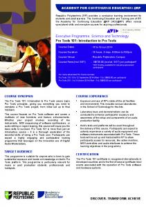
Drilling machines are machine tools designed for drilling holes in metallic and non-metallic materials. In drilling the unstressed grains of the metal are removed continuously by the cutting edge of a drill. The main function of drilling machines are drilling holes, tapping, reaming and other general purpose, small-diameter boring operations. The principal cutting tool used for carrying out drilling operations is the drill. The most common type of drilling machine and its major components are shown in Fig. 11.8. The workpiece is placed on an adjustable table, either by clamping it directly into the slots and holes on the table or by using a vise, which in turn can be clamped to the table. The workpiece should be clamped, both for safety and accuracy. The drill is lowered manually by
INTRODUCTION TO MACHINE TOOLS
231
hand wheel or by power feed at preset-rates. In order to maintain proper cutting speeds at the cutting edges of drills, the spindle speed on drilling machines has to be adjustable to accommodate different sizes of drills. Adjustments are made by means of pulleys, gearboxes or variable speed motors. The drill is placed in the chuck and when the machine is “ON” the drill rotates. The linear motion is given to the drill towards the workpiece which is called feed. Types of drilling machines range from simple bench-type units, used to drill small diameter holes, to large radial drills, which can accommodate large workpieces. Drilling machines with multiple spindles are used for high production rate operations. Multiple-spindle machines are also used for reaming and counterboring operations.
11.3.1 Principal Parts of the Drilling Machine The most common type is bench drilling machine, the major components of which are as follows: 1. 2. 3. 4. 5. 6.
Head: Contains the electric motor, V-pulley, and V-belt. Spindle: It rotates as well as moves up and down in the sleeve. Drill chuck: Holds the drill bit. Adjustable table: Moves vertically, horizontally. Base: Supports the column, supports the table, head, etc. Column: Vertical round or box section.
Fig. 11.7
Bench Drilling Machine (Portable type)
232
MANUFACTURING SCIENCE
11.3.2 Types of Drilling Machine Different types of drilling machines are as follows: 1. Portable drilling machine. 2. Bench type drilling machine. 3. Sensitive drilling machine. 4. Upright drilling machine. 5. Radial drilling machine. 6. Multi spindle drilling machine. 7. Deep hole drilling machine. 8. Gang drilling machine. 9. Automatic drilling machine.
11.3.3 Drilling Operations The following are the most common types of operation performed on the drilling machine: 1. Drilling: Drilling is the operation of making circular holes in the workpiece. 2. Boring: Boring is the operation of increasing the diameter of a hole previously formed in some way not necessarily by drilling. 3. Reaming: Reaming is an operation used to make an existing hole dimensionally more accurate than can be obtained by drilling alone and to improve its surface finish. 4. Tapping: Internal threads in workpieces can be produced by tapping. Tapping may be done by hand or in drilling machine or lathes, using tapping heads to hold the tap. 5. Counter boring: Enlarging the entry of a drilled hole. In other words, counter boring produce depressions on the surface to accommodate the heads of screws and bolts. Countersinking produces inclined sides of depression for screw heads. Fig. 11.9 shows different operations on drilling machine. The cutting end of the drill is shown on larger scale in the same figure.
11.3.4 Specifications of a Drilling Machine • • • •
Drilling capacity, Traverse of spindle, Working surface of table (i.e., diameter), Range of spindle speeds,
INTRODUCTION TO MACHINE TOOLS
• • • •
233
Range of power feed per revolution, Distance between spindle and column, Motor speed, Motor power, etc.
Fig. 11.9 Various operations on Drilling machine
11.4 PLANER The planer is also called a planning machine. Planning is a relatively simple cutting process by which flat surfaces, as well as various cross-sections with grooves and notches, are produced along the length of the workpiece. Planer is a large machine tool used for machining flat surfaces by means of single point cutting tools, on large size work pieces. In a planer, the workpiece is mounted on table that reciprocates along a straight path. A horizontal cross-rail, which can be moved vertically along the ways in the column, is equipped with one or more tool heads. The cutting tools are attached to the heads and machining is done along a straight path. Because of the reciprocating motion of the workpiece, elapsed non-cutting time during the return stroke is significant in planning. Fig. 11.10 shows the arrangement of planning machine. The principal parts of a planer are: bed, table, housing or columns, cross-rail, tool heads, etc. Planers may be used in medium and heavy engineering plants for single piece and small lot production and also in repair shops.
11.4.1 Types of Planers The various types of planers commonly used are: 1. Double housing planner. 2. Open side planner.
234
MANUFACTURING SCIENCE
3. Pit planner. 4. Edge or plate planner. 5. Divided table planner. The double housing planner is commonly used in engineering industries.
Fig. 11.8
Planers
11.4.2 Specifications of a Planner The specifications of a planners are as follows: • Width of the table. • Maximum distance of the table to the cross rail in metres. • Maximum stroke of the table in mm, other additional particulars. • Length of bed. • Length of table. • Type of drive. • Power of the motor. • Number of speed and feed.
11.4.3 Operations Performed on Planner The common operations performed on a planner are as follows: 1. Machining horizontal flat surface. 2. Machining vertical flat surface.
235
INTRODUCTION TO MACHINE TOOLS
3. Machining angular surface. 4. Machining different types of slot and grooves. 5. Machining curved surfaces.
11.5 SHAPER The shaper is also known as shaping machine. Shaping differ from planning in that it is carried out on small areas. Metal cutting by shaping is basically the same as in planning. In a horizontal shaper the tool travels along a straight path and workpiece is stationary. It contrasts with planner in that the job in planer reciprocates and tool remains stationary. Shaper is mainly used for producing plane surface by means of a single point tools. In shaping, a tool is given a reciprocating motion. The flat surfaces may be horizontal, inclined or vertical. A shaper is shown in Fig. 11.11.
Fig. 11.11
Parts of a shaper
236
MANUFACTURING SCIENCE
11.5.1 Working Principle of a Shaper In shaping machine, the tool held in the tool holder mounted on the ram moves forwards and backwards in a straight line over the work piece rigidly held in a suitable device (generally vice) over the work table. The ram reciprocates to and fro, and in doing so cuts the material held in the vice during the cutting stroke. The job is given an index feed with the help of a cross-rail mechanism fitted inside the table.
Fig. 11.12
Shaping and planning
The shaper and planner operations differ as shown in Fig. 11.12. The shaper and planner use single point tools. The tool is carried on the rigid arm or “ram” moving horizontally and located within the body. A rocker ram furnishes a constant thrust during cutting. Regulation of the stroke during operation is perfectly feasible. The tool-box is secured on the ram, and can be set to angular graduations up to 45 deg. each side of the vertical. The table is furnished with slots to secure the parts to be shaped. The ram motion gives the cutting movement. The table is movable vertically according to the type of work, or transversely to provide the feed movement and ram is especially set to give the desired cut, but, for vertical surfaces, a vertical-feed movement is given to the tool. Surfaces at an angle can also be shaped if the tool is correctly adjusted to the proper angle. The stroke of the ram is governed by the length of the surface to be shaped. The center of the stroke is controlled by a connecting rod moving in a slot in the ram. The stroke length may be modified if required. The shaper begins to cut and finishes cutting more slowly than in between, so that the cutting tool is not too severely stressed when entering the work. The bed also carries a saddle-supported work table raised or lowered to suit the height of the work. Drive is by belt, hydraulic cylinder or electric motor. The table can be moved laterally, either manually or automatically, along the saddle at regular intervals for shaping. A quick return motion mechanism (Fig. 11.13) gives shaper ram a reciprocating motion. The tool cuts only in forward motion, starting slowly and ending the cut slowly. In between the tool moves faster. The return stroke is faster than cutting stroke. It saves time. A circular disc, A (normally a gear) rotates uniformly about centre C and carrier an eccentric point E which carries a rectangular block. This block slides in a slot in arm BD. The arm is connected to pin at D which is on ram. As the arm swings between extreme positions BD and BF, the
INTRODUCTION TO MACHINE TOOLS
237
ram and hence tool reciprocate. From D to F, tool has return stroke taking less time than for forward motion from F to D. As the pin rotates in a circle, the arm BD oscillates between BD and BF. The forward or cutting stroke takes time of rotation of disc over angle 360º–angle GCH. This angle is greater than angle GCH. The return stroke, in which tool does not cut takes time for disc to rotate through angle GCH. Thus return strokes is faster. The cutting force is obtained from force exerted by arm BD at D.
Fig. 11.13
The diagram shows the principle of the Whit Worth quick-return motor for shaping machines.
11.5.2 Principal Parts of a Shaper The principal parts of a shaper are as follows: • Base • Column (Body) • Cross-rail • Table and knee • Ram • Tool Head • Motor (See Fig. 11.11)
11.5.3 Classification of Shaper Shapers may be classified on the basis of: 1. Ram driving mechanism (a) Crank shaper (b) Geared shaper (c) Hydraulic shaper
238
MANUFACTURING SCIENCE
2. According to the position and travel of Ram: (a) Horizontal shaper (b) Vertical shaper (c) Travelling head shaper 3. According to the direction of cutting stroke: (a) Push cut shaper (b) Draw cut shaper 4. According to the design of the table: (a) Standard or plain shaper (b) Universal shaper
11.5.4 Specification of a Shaper The shaper is specified as follows: • • • • • • •
Maximum length of stroke. Maximum horizontal travel of table. Maximum vertical travel of table. Size of the table, i.e. length, width, and depth of the table. Maximum vertical travel of tool slide. Maximum number of stroke per minute. Type of quick return mechanism.
11.5.5 Operations Performed on a Shaper 1. 2. 3. 4. 5.
Horizontal cutting. Cutting vertical and angular surfaces. Irregular cutting. Machining a thin job. Key way cutting.
11.6 SLOTTER A slotter is a heavy duty shaping machine in which the cutting tool moves vertically. It is also known as slotting machine. The machine operates in similar to the shaper, however, the tool moves vertically rather than in a horizontal direction. The job is held stationary. The slotter has a vertical ram, mounted on an independent bearing, the upper part of which is pivoted, to shift the ram in any angular position. A slotter performs a variety of operation, such as the finishing of external and internal plain surface as shown in Fig. 11.14. The main parts of slotter are; bed, column, cross-slide, table and ram, etc.
INTRODUCTION TO MACHINE TOOLS
Fig. 11.14
Slotting machine and its principal parts
11.6.1 Specification 1. Maximum stroke. 2. Diameter of circular table. 3. Transverse movement of table. 4. Longitudinal movement of table. 5. Swing of ram. 6. Number of speeds. 7. Maximum drawing force. 8. Motor for drive of machine. 9. Floor space required by machine. 10. Width and spacing of T-slots.
239
240 11.6.2
MANUFACTURING SCIENCE
Types of Slotter
There are mainly three types of slotters: 1. Puncher slotter. 2. General production slotter. 3. Key slotter.
11.6.3 Slotter Operation (i) (ii) (iii) (iv)
11.7
Internal grooves or key ways. Internal gears. Recesses. Concave, circular and convex surface.
MILLING
Milling is a method of giving a specific shape or form to metal by cutting them with relatively slowly revolving tools, commonly known as milling cutters. The milling operation is quicker and more accurate in forming surface than shaping and planning. Of course milling operations are many more than surfacing. Basically milling machine is a machine tool in which metal is removed by means of a revolving cutter. A milling cutter has a series of cutting edge on its circumference. Each edge acts as an individual cutter during the cycle of rotation. The work may be fed to the cutter, longitudinally, transversely, or vertically. The cutter is set to a certain depth of cut by raising the table. The milling machine itself can be roughly described as a machine in which the work to be milled is affixed to a movable table and passed under a revolving cutter. In this way both plain and irregular surface can be formed by milling machine as shown in Fig. 11.15. It was invented by Eli Whitney in 1818. Milling machine is employed
Fig. 11.15(a)
Schematic illustration of a horizontal-spindle column-and-knee type milling machine
241
INTRODUCTION TO MACHINE TOOLS
Fig. 11.15(b)
Principal parts of a milling machine
for machining flat surfaces, surface of revolution, external and internal threads and helical surfaces of various cross-sections. Some milling operations are shown in Fig. 11.16. The same figure shows the geometry of cutter. A face milling cutter can cut both vertical and horizontal surfaces. An end milling cutter can produce large recess or a slot. This machine is suitable in tool room work due to its variety of operations and better surface finish. The milling machines are of various types and can be grouped under four main headings: 1. Universal milling machine, 2. Plain milling machine, 3. Vertical milling machine, 4. Manufacturing millers.
242
MANUFACTURING SCIENCE
Fig. 11.16
Some milling processes and cutters
11.7.1 Specification of Milling Machine The milling machine is specified by: • Table working surface. • Longitudinal, cross and vertical traverse. • Range and number of spindle speeds. • Power of machine and machine type.
11.7.2 Principal Parts of a Milling Machine • Base • Column • Knee: Supports the saddle and gives the table vertical movement for adjusting the depth of cut. • Saddle: Supports the table and can move transversely. • Table: On which the workpiece is clamped using the T-slots. The table moves longitudinally with respect to the saddle. • Over arm: In horizontal machine, over arm, is adjustable to accommodate different arbor lengths. • Spindle is driven by motor and internal gearing. • Arbor is fitted to spindle on one side and supported in bearing attached to over arm. It is a kind of shaft on which tools are carried between cylindrical spacers.
INTRODUCTION TO MACHINE TOOLS
243
11.7.3 Classification of Milling Machine Milling machines are classified in various groups. (a) According to design, milling machines are classified as: (i) Column and knee type milling machine. (ii) Planner milling machine. (iii) Fixed bed type milling machine. (iv) Special machines, i.e. rotary table, duplicating. (b) Depending upon the position of the spindle, milling machine are classified as: (i) Horizontal spindle milling machine. (ii) Vertical spindle milling machine.
11.7.4 Milling Operations The following are the important operations performed on milling machine: • Plain milling, • Face milling, • Angular milling, • Side milling, • Form milling, • Gang milling, • End milling, • Milling T-slots, • Milling keyways, Grooves, Slots, etc.
11.8 MACHINING PROCESSES Machining is the process of removing unwanted material from a workpiece in the form of chips. If the workpiece is a metal, the process is often called metal cutting or metal removal processes, which refer to the removal of certain selected areas from a part to obtain a desired shape of the object. Chips are formed by interaction of a cutting tool with the material being machined. Cutting tools are used to perform the basic and related machining processes as shown in Fig. 11.17 only for Lathe machine. The cutting tools are mounted in machine tools, which provide the required movements of the tool with respect to the work to accomplish the desired process.
244
MANUFACTURING SCIENCE
Fig. 11.17 Turning, facing, boring, and related processes typically done on a lathe. The arrows indicate the motion of the tool relative to the work
The basic lathe machining processes are: turning (plain and taper); facing, shoulder, contour and form turning; parting and necking; boring and drilling, taper boring and internal forming on internal cylindrical surface; external and internal threading and knurling on outside surface. These are shown in Fig. 11.17.
245
INTRODUCTION TO MACHINE TOOLS
1. Facing: Facing is the producing of a flat surface as the result of the tool being fed across the end of the rotating workpiece. The cutting speed should be determined from the largest diameter of the surface to be faced. Facing may be done either from the outside to centre or from the centre to outward. The cutting force tends to push the tool away from the work, it is usually desirable to clamp the carriage to the lathe bed during each facing cut to prevent it from moving slightly and thus producing a surface that is not flat. In facing, the tool feeds perpendicular to the axis of the rotating workpiece as shown in Fig. 11.18(a)
Fig. 11.18 2. Turning: Turning constitutes the majority of lathe work. Turning is the process of machining external cylindrical and conical surfaces. In turning processes, the workpiece is rotated about machine axis and a single point tool is fed along the axis. If good finish and accurate size are desired, one or more roughing cuts usually are followed by one or more finishing cut. Roughing cut may be as heavy as the machine may permit. Finishing cuts are light, usually being less than 0.375 mm indepth with the feed as fine as necessary to give the desired finish. Sometimes a special finishing tool is used, but often the same tool is used for both roughing and finishing cuts. In turning the primary cutting motion is rotational with the tool feeding parallel to the axis of rotation as shown in Fig. 11.8(b). The length of cut is the distance traveled parallel to the axis, plus some allowance. If the tool is fed at an angle to the axis of rotation, an external conical surface results that is known as taper turning. Such motion of tool is obtained through cross-slide. 3. Boring: Boring involves the enlarging of an existing hole, which may have been made by a drill. Essentially, boring is internal turning. Boring can use single-point cutting tools to produce internal cylindrical or conical surfaces. It does not create the hole but rather machines or enlarges the hole to a specific size. Boring can be done on most machine tools that can do turning.
246
MANUFACTURING SCIENCE
When boring is done in a lathe, the work usually is held in chuck or on a face plate. Holes may be bored straight or tapered. Fig. 11.18(c) shows that an internal hole of diameter D2 is being enlarged to hole of diameter D1. The cutting tool in form of a bit is carried at the end of a cylindrical bar which does not rotate. The top of the tool bit is at a radius of D1/2 and diameter of bar is less than the diameter D1. The boring bar may be carried in tail stock or in tool post.
Fig. 11.18
4. Parting: Parting is the operation by which one section of a workpiece is separated from the remainder by means of a cut-off tool as shown in Fig. 11.18(d). In otherwords, if the tool is fed all the way to the axis of the workpiece, it will be cut in two that is known as parting. The parting tools are quite thin and must have considerable overhang, this process is more difficult to perform accurately. The tool should be set exactly at the height of the axis of rotation, be kept sharp, have proper clearance angles, and be fed into the workpiece at a proper and uniform feed rate. In parting, the tool is fed perpendicular to the rotational axis, as in facing. The length of cut for solid bars is D/2. 5. Drilling: Drilling is the operation of making holes in a material. The process is very frequently confused with boring, a term which should only be used for the operation of increasing the diameter of a hole previously formed in some way. There are several forms of drill which may be held and rotated so as to pierce the work in many types of machine. Drilling on lathes is done with the drill mounted in the tailstock of lathes and fed by hand against a rotating workpiece. It is also possible to drill on a lathe with the drill bit mounted and rotated in the spindle while the work remains stationary, supported on the tailstock or the carriage of the lathe. In drilling deep holes, the drill should be withdrawn occasionally to clear chips from the hole and to aid in getting coolant to the cutting edges. 6. Reaming: The process of reaming has a number of applications, out of which following are important.
INTRODUCTION TO MACHINE TOOLS
247
1. To enlarge existing drilled holes, by small amount. 2. To make a parallel hole into a tapered holes. 3. To bring existing holes accurately to size. There are two types of reamer, one of which is parallel and the other is tapered. Reaming on a lathe involves no special precautions. Reamers are held in the tailstock, taper shank types being mounted directly and straight-shank types by means of a drill chuck. 7. Knurling: Knurling produces a regularly shaped, roughened surface on a workpiece. Knurling is a chipless, cold-forming process, using a tool. In this process of machining, the two hardened rolls are pressed against the rotating workpiece with sufficient force to cause a slight outward and lateral displacement of the metal so as to form the Knurl, a raised diamond pattern. Another type of Knurling tool produces the Knurled pattern by cutting chips. The use of a Knurled surface is either to facilitate handling or to replace keying or screwing light cylindrical pieces together as fitting B into C. The process is one of the producing a series of right and left hand fine grooves in the material as shown in Fig. 11.8(e).
Fig. 11.18(e)
Examples of diagonal knurling and serrating. The burring action of tool A produces a series of fine grooves in the material: it can also produce straight serrations along the axis on the surface.
8. Threading: Thread is one of most important features on cylindrical surface. Threading refers to the manufacturing of threads on external or internal surface of a cylinder.
248
MANUFACTURING SCIENCE
Lathe provided the first method for cutting threads by machining. Although most threads are now produced by other methods, lathe still provides the most versatile and fundamentally simple method. Consequently, lathe is used for cutting threads on special workpieces where the configuration or nonstandard size does not permit them to be made by less costly method. External threads can be cut with the work mounted either between centres or held in check. For internal threads, the work must be held in a chuck. The cutting tool usually is checked for shape and alignment by means of a threa template. If the tool is fed radially, cutting takes place simultaneously on both sides of the Vshaped tool. Proper speed ratio between the spindle and lead screw is set by means of the gear box. Modern lathes have ranges of ratios available so that nearly all standard threads can be cut merely by setting the proper leverson the quick change gear box. Thread cutting on lathe is shown in Fig. 11.19. The arrangement shows the cylindrical job held between centres and a V-tool supported in tool holder perpendicular to the axis of rotation of the job. The head stock spindle is connected to the lead screw through a gear train in which middle gear is idle. For each rotation of spindle the lead screw has a fixed number of rotation and causes the carriage and hence tool to move through a fixed distance. The tool is given a transverse feed equal to the depth of the thread and thus the thread is cut as job rotates.
Fig. 11.19 Types of cutting
The thread is a standard feature defined by pitch (or number of threads per mm), the angle of V and depth of V. The tool is ground to required angle and checked on thread gauge.
INTRODUCTION TO MACHINE TOOLS
11.9
249
CUTTING PROCESS AND CUTTING TOOL
The production process in general consists in shaping and cutting metals or other materials, into desired forms and dimensions. In cutting process metal is removed from surface by generating a relative motion between cutting tool and the body. The metal is removed in form of a chip and the forces are exerted on the workpiece and the tool. While workpiece gets the desired shape and size, the tool gets worn. The shape of the tool, the relative speed and forces affect the life of the tool and surface finish. The time and material are consumed and hence the cost is incurred.
Fig. 11.20 Types of cutting
A cutting tool may be single point or multipoint. Single point cutting tool has a wedge like action, wedging between workpiece surface and chip and is used in turning, shaping, boring, slotting etc. A multipoint cutting tool having two or more cutting points is used in such cutting processes as milling, broaching etc. Two basic cutting processes are identified as orthogonal (or two dimensional) and oblique (or three dimensional). In orthogonal cutting the cutting edge of the tool is at right angle to its motion. In oblique cutting the edge of the tool is inclined to the direction of relative motion at angles less than 90º. Fig. 11.20 illustrates two types of cutting.
250
MANUFACTURING SCIENCE
The orthogonal cutting is confined to such operations as turning, broaching and slotting. Bulk of machining involves, oblique cutting.
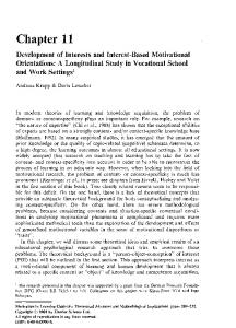
11.9.1 Tool Geometry Three views of a single point cutting tool are shown in Fig. 11.21. The nomenclature is as follows: Shank: Shank is the main body of cutting tool, normally rectangular in cross-section and is held in the holder. It is not ground. Marked as 1. Face:
It is face against which the chip slides upwards. Marked as 2.
Flank:
Marked as 3 and 4 are surfaces facing the workpiece. 3 is side flank while 4 is end flank (Seen in side view).
Cutting The lines of intersection of face with end and side flanks are cutting edges, marked edges: as 5 and 6 respectively, are end cutting edge and side cutting edge (seen in top view). Nose:
Slightly rounded, it is the point where two cutting edges meet (seen in top view).
Tool angles A – front rake angle B – lip angle C – front clearance angle D – side rake angle E – side clearance angle F – side cutting edge angle G – end cutting edge angle H – nose angle
Fig. 11.21 Geometry of a single point tool
Heel:
The lowest portion of cutting edges is called heel.
Rake:
All surfaces and edges slope back from the nose and cutting edges. This is called rake and measured by various rake angles.
Base:
Underside of the shank is the base of the tool.
Various characteristic angle of tool are described in Fig. 11.21.
INTRODUCTION TO MACHINE TOOLS
251
11.9.2 Chips The removal of material in metal cutting process is in form of chips. Chip is a form of material to be discarded (waste) but since volume may be large, they can be collected and disposed off in a useful way. Chips can be collected by allowing gravity to drop them on a steel conveyor belt, dragging the chips from a settling tank, using magnetic conveyors (for ferrous chips), or using vacuum methods of removal. It should be noted that there is a considerable amount of cutting fluid mixed in with the chips produced, and proper filtration or draining is important. These systems usually require considerable floor space; consequently, modern machine tools are designed with automated chip handling features. The collected chips may be dumped (provided they are free of harmful chemical components or fluids) or they may be recycled. Prior to their being hauled away from a manufacturing plant, the large volume of chips can be reduced to as little as one-fifth of the loose volume by compaction (crushing). Dry chips are more valuable for recycling in foundries. The final method of chip disposal depends on economics as well as meeting local, state, and federal regulations. Three types of chips are obtained from metal cutting process i.e. when a cutting tool cuts through the surface of metallic workpiece. These are: 1. Discontinuous chip 2. Continuous chip 3. Continuous chip with built up edge 1. Discontinuous Chip: The chips are small individual segments which may adhere loosely to each other. These segments are regularly formed due to the rapture of the metal ahead of the tool. The repture of metal takes place when the metal directly above the cutting edge gets compressed as shown in Fig. 11.22(a). The metals like cast iron and brass casting produce discontinuous chips. The factors responsible for the formation of discontinuous chips are: (i) Brittle and non-ductile metals. (ii) Low cutting speed. (iii) Small rake angle. 2. Continuous Chip: Such chips are ribbon like in the form of long coils having the same thickness throughout the length of the coil. The chips are produced due to continuous plastic deformation of the metal along the shear plane without rupture. Continuous chips are obtained at high speeds when the surface finish improves. A continuous chip is shown in Fig. 11.18(b). The factors responsible for continuous chips are given below: (i) (ii) (iii) (iv) (v)
Ductile material High cutting speed Large rake angle Sharp cutting edge Low friction at tool chips interface
252
MANUFACTURING SCIENCE
Low carbon steel copper, brass and alloys of Al produce continuous chips. These chips continuously rub against tool causing heat generation and power loss. The tool is also damaged.
Fig. 11.22 Types of chips
3. Continuous Chip with Built up Edge: Such chips also appear in the form of long coils, but they are not as smooth as in continuous chip formation. On closely observing the cutting edge of the tool a small lump of metal welded to the chip tool contact area can be located at cutting edge. Some material also remains welded to workpiece surface resulting in poor finish. This kind of chips are formed due to high pressure at the cutting edge. The lump of metal is known as built-up edge. Factor responsible for continuous chips with built up edge are: (i) Ductile material (ii) Coarse feed (iii) Small rake angle (iv) Low cutting speed (v) Insufficient coolant Continuous chips have to be broken from time to time. Their continuous formation is clumsy and rubbing with tool wastes power and causes damage to tool.
QUESTIONS 1. What is turning operation? On what machine turning is performed? Describe leading parts of the machine used for turning. 2. What function does a chuck perform in lathe machine? Sketch a 3-jaw chuck holding a cylindrical workpiece being cut by a tool. 3. Sketch a tailstock and explain its function. What is a live centre and when do you use it in turning? 4. What are mandrels? Describe solid, gang and cone mandrels? 5. Figure below shows turning operation on a lathe. Identify the parts marked from 1 to 10. What other operations can be performed on lathe.
INTRODUCTION TO MACHINE TOOLS
253
6. How do you specify a lathe? Make a list of specification. 7. What is a form tool? What difficulties are faced when using a form tool on lathe? Sketch a form tool and corresponding shape. 8. Figures below show two types of same machine. Identify the machine and describe functions of (a) and (b). Identify parts that are marked. What do the arrows represent?
9. Sketch a planer and explain how does a planer differ from a shaper. Make a list of specifications of a planer and another list of operations. 10. Two views (elevation and side view) of a metal cutting machine are shown in figure below. Identify the machine and parts marked. The arrow on part two indicates reciprocating motion. How is this motion obtained. Sketch the mechanism name it and describe it.
254
MANUFACTURING SCIENCE
11. Differentiate between a slotter and a shaper. Give specification of both machines. Which will be preferred for making a keyway? 12. Sketch a milling machine and show leading parts. What operations are carried out on milling machine? What is the difference between a milling cutter and a lathe tool? Which tool is similar to that used on shaper and planer? 13. Describe types of cutting and show them on sketch. What are the characteristics of single point tool? 14. Three figures (a) (b) and (c) show metal cutting operations. On which machine they are performed? Identify the operations?
15. Describe thread cutting operation on lathe.