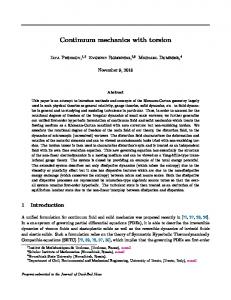
This chapter reviews some of the key elements of continuum mechanics that are
essential to both the understanding and development of the theory of plasticity.
CHAPTER 2 ELEMENTS OF CONTINUUM MECHANICS
2.1 INTRODUCTION This chapter reviews some of the key elements of continuum mechanics that are essential to both the understanding and development of the theory of plasticity. These concepts are mainly concerned with the analysis of stress and strain, equilibrium equations and compatibility conditions, as well as elastic stress-strain relations. The reader is referred to other texts such as Prager (1961), Fung (1965), Timoshenko and Goodier (1970), Spencer (1980) and Malvern (1969) for a detailed treatment of continuum mechanics. 2.2 STRESS STATE AND EQUILIBRIUM 2.2.1 IWo-dimensional elements As shown in Figure 2.1, the stress state for a two-dimensional element is defined by four stress components Oxx, Oyy, Oxy and Oy^. The moment equilibrium demands that two shear stresses are equal in magnitude, namely Oxy = Oyx- Note that compressive stresses are treated as positive here. O^w
[Or C7„, t
B
I -
"
A
1
Figure 2.1: Stress state for two-dimensional elements These stress components can be displaced as elements of a square matrix: a,•yx
O,
yy\
CHAPTER 2
11
The two most frequent cases of two-dimensional engineering problems are those of plane stress and plane strain. For the case of plane stress, the stresses normal to the xy plane are assumed to be identically zero. On the other hand, the case of plane strain only has non-zero strain components in the xy plane. In this case, the normal stress in the direction normal to the xy plane may be determined from the stresses acting on the xy plane {Oja, Oyy, Oxy) through elastic stress-strain relations that will be discussed later in this chapter Whilst plane stress is a good assumption for simplifying many engineering problems in structural and mechanical engineering, plane strain is most relevant in geotechnical engineering. This is because many important geotechnical problems, such as embankments and tunnels, may be adequately analysed as a two-dimensional plane strain problem. (a) TVansformation of stresses and principal stresses Now let us investigate the stress components at the point with respect to a new coordinate system {x'oy'), which is obtained by rotating the original coordinate system {xoy) anticlockwise by an angle of 6 (see Figure 2.1). It can be easily shown that the stresses in these two coordinate systems are related by the following equations: (^x'x' = ^"^ 2 ^ ^ ^ (^yy^^^
^,05 20 - o^ sin 20
(2.1)
Oyy = ^"^ 2 ^ ^ ~ ^ ^ 2 ^ " cos 20 + o^^ sin 20
(2.2)
a^y = o^ cos 20 H- ^ ^ " ^ " ^ sin 20
(2.3)
The principal stresses are those acting on a principal plane where shear stress is zero. The principal planes can be determined by setting equation (2.3) to zero, which gives: tan20 = 5 - ^ ^
2.4)
Substituting the above solution into equations (2.1) and (2.2) leads to the expressions for the two principal stresses: Oxx + (^yy 1
/(^^)^ + 4
(2.5)
/ ( ^ " : ^ ^ )2 + a^
(2.6)
^1
2
^
^2
(^xx ' (^yy 9
1
where o^ and CTJ are also known as the major and minor principal stresses respectively.
12
ELEMENTS OF CONTINUUM MECHANICS
The transformation of stresses, analytically expressed by the above equations, can also be simply achieved by using a Mohr-circle construction. Assume that the positive plane normal to the x direction is denoted by A and the positive plane normal to the y direction by B. Whilst compressive normal stresses are regarded as positive, shear stresses acting clockwise are treated as positive.
Shear stress
Normal stress
Figure 2.2: Transformation of stresses using a Mohr-circle construction Using the Mohr-circle construction shown in Figure 2.2, the stresses on the plane A and B are defined by the coordinates of points A and B in the Mohr-circle. The stresses for the corresponding planes A'and B' with respect to a new coordinate system (x'oy') are equal to the coordinates of the points A'and B' in the Mohrcircle. It is noted that the points A'and B'are arrived by rotating the points A and B respectively by two times the angle between the coordinate systems (xoy) and (x'oy'). By definition, the principal stresses are the coordinates of the interaction points between the Mohr-circle and the normal stress axis. (b) Equations of interior stress equilibrium By accounting for stress variation with coordinates, equations of stress equilibrium can be established. It is instructive to first consider all the stresses in the x direction, as shown in Figure 2.3. The quantity X is assumed to be the body force (i.e. force per unit volume). The equation of force equilibrium in the x direction leads to the following equation of stresses: dx
doxy By
X
(2.7)
CHAPTER 2
13
Similarly consideration of the force equilibrium in the y direction gives the second equation of stresses: dOxy ^ dOyy _
dx
^^
(2.8)
dy
where K denotes the body force in the y direction.
dy Orx +
^-^dx ax
axy
dx Figure 2.3: Equation of stress equilibrium Equations (2.7) and (2.8) are known as the equations of interior stress equilibrium for two-dimensional problems. (c) Equations of boundary stress equilibrium When some part of a boundary is subject to tractions (shear and normal components), they need to be in equilibrium with interior stresses acting surrounding that part of the boundary.
dy
Figure 2.4: Equilibrium of interior stresses with tractions applied on a boundary
14
ELEMENTS OF CONTINUUM MECHANICS
Let us assume that the orientation of the boundary with iinown tractions is denoted by the angle a, as shown in Figure 2.4. The equilibrium of the triangular element requires: cos a -H Oxv sin a = T^,
(2.9)
Oxy cos a + Oyy sin a = Ty
(2.10)
where Tx and Ty are the applied traction components in the x and y directions.
Z n
Figure 2.5: Stress state for three-dimensional elements 2.2.2 Three-dimensional elements (a) Stress tensor The state of stress for a three-dimensional point is defined by a matrix containing nine stress components shown in Figure 2.5. The nine components of the stress at any point form a second order tensor, known as the stress tensor o^j , where / and j take integral values 1,2 and 3. In this way, the stress components can be expressed as elements of a square matrix: Oxx Oyx
Oxy Oyy
Oxz Oyz
Ozx
Ozy
Ozz
'13 O 23
O-x '31
O. ^32
=
On
(2.11)
O. '^SSJ
As in the two-dimensional case, moment equilibrium demands the following relationships on shear stresses: Oxv Jxy = O,yx ;
Oxz = Oz
Oyz = O:zy
(2.12)
As a result there are only six independent stress components: three normal stresses {Oxx, Oyy, a^^ and three shear stresses {Oxy, Oy^, Oxz)-
CHAPTER 2
15
(b) Principal stresses The state of stress at a point in three dimensions can also be defined by three principal stresses 0^,02 and 03. These principal stresses are linked to the components of the stress tensor by the following cubic equation: o^ - I]0 + /20- + /3 = 0
(2.13)
where /,, /2 and 73 are known as the first, second and third stress invariant respectively, which are defined as follows: 1^=- a^ + Oyy + o^,
(2.14)
12 = Oxx Oyy + Oyy Oyy + O^z O^X " O^y^ " (Ty/ " O^^^
(2.15)
^3 ~ Oxx ^yy ^zz ~ ^xx ^yz ~ ^yy ^^xz -
Ozz Oxy^
+ 20xy Oyz Oxz
(2.16)
The stress tensor in terms of the principal stresses takes the form o-i 0 ,0
0 0