Key words: UML 2.0, Structured classes, Interactions, State machines. 1. .... secret personal identification (PIN code). ... to many from their daily life.
Chapter 3 STRUCTURAL MODELING WITH UML2.0 Classes, Interactions and State Machines Øystein Haugen1, Birger Møller-Pedersen1, Thomas Weigert2 1
Ericsson, 2Motorola, Inc.
Abstract:
This chapter will provide an overview of the structuring concepts that are proposed for the coming UML 2.0. This will be done through an example. We will illustrate that these concepts are designed such that structuring applied to classes may be reflected in the corresponding structuring of the interactions between the parts of a class.
Key words:
UML 2.0, Structured classes, Interactions, State machines
1.
STRUCTURAL CONCEPTS OF UML 2.0 – THE ORIGINS
The structuring of systems in terms of their constituents and the topology of connections between these constituents have been addressed by various communities, and a number of languages and notations have been designed in its support. While programming languages often merely provide the general mechanism of object references, specification and modeling languages typically support more advanced structuring mechanisms. In the telecom industry, specifying systems as a set of interconnected (composite) blocks was common practice already in the seventies [1]. SDL was one of the first standardized notations for modeling and specification with support for such structuring mechanisms [2]. In the 1984 version, the notion of systems consisting of entities executing state machines that define their behavior and connected by communication links was introduced. Object-orientation was first proposed for SDL in 1987 [3]; in 1992 these concepts became part of the language, when types of entities and gates as connection points for communication links were introduced. In addition, 1
2
Chapter 3
specialization was defined for types of entities with an internal structure of connected parts, and for state machines. Proprietary variations of sequence diagrams (these were often referred to as “message flow graphs” or “bounce diagrams”) had long been in use in the telecom industry. The standardization of Message Sequence Charts (MSC) was triggered by a paper by Rudolph and Grabowski [4], leading to the first MSC recommendation in 1992. MSC-2000 [5] refined earlier structuring mechanisms such as MSC references and inline expressions. UML chose a somewhat different dialect similar to, but not identical to MSC-92, as the foundation of sequence diagrams, and did not support reuse and hierarchy. With UML 2.0, the two dialects have reached more or less the same expressiveness. In 1987, Harel introduced structuring mechanisms for state machines [6]. While then state machine-based languages relied on “flat” state machines (albeit SDL supported hierarchy through calls to procedures in turn specified by state machines), Harel’s state machines were explicitly hierarchical, with composite states containing in turn states and transitions. Work on Architecture Description Languages began in the early nineties (see, for example, [7]). This area has produced a number of modeling languages such as ACME [8] and Rapide [9] which aim at analyzing certain properties of a system based upon the description of its architecture, without considering the detailed specification of its behavior. In 1994, ROOM [10] combined statecharts and structuring mechanisms like those of SDL, inspired by the Chorus distributed operating system. While SDL gates are just connection points, ROOM introduced more general ports, i.e., boundary objects mediating the communication between connected objects. ROOM further introduced the ability to associate protocol specifications to both ports and connectors. From the world of data and object modeling came the notion of contextual composition, i.e. composition with contextual links between parts of the composite [11]. In 1997, Harel and Gery applied the same structuring mechanism that had been proposed for SDL [3] earlier to statecharts, especially the mechanisms for specializing behavior specified through state machines [12]. SDL-2000 [13] adopted the ROOM port concept, as well as the hierarchical state machines of statecharts. However, it extended the latter with connection points taken from its structuring mechanisms. When UML 1.1 was adopted, only few of these structuring mechanisms became part of the language. Lessons learned with respect to the lack of structuring mechanisms for UML have been summarized in [14] and [15]. The structuring mechanisms of the coming UML 2.0 are based upon experiences with all these efforts.
3. STRUCTURAL MODELING WITH UML2.0
3
These languages have formalized what engineers and system designers have been doing all along: making informal “block” or “structure” diagrams for various reasons. Interconnected blocks were used in order to specify the structures (in terms of instances) of the complete running systems, statecharts were introduced in order to specify structures of state machines, while message sequence charts pioneered the structuring of behavior in a declarative manner.
2.
EXAMPLE – AN ACCESS CONTROL SYSTEM
This chapter will use one example – an access control system – to explain how UML 2.0 structural concepts can be used to model a system in a compact, but readable way. This example has earlier been elaborated in the TIMe method [16].
2.1
Introducing the Example – Domain Statement
In order to give the reader a first insight into our example system, we present the structured domain statement in natural English. At this stage many UML users would also apply use cases. We have chosen to omit the use cases to save space and since our focus is on the structuring mechanisms. Area of Concern: Access control has to do with controlling the access of users to a set of access zones. Only a user with known identity and correct access rights shall be allowed to enter into an access zone. Other users shall be denied access. Services – User Access: The user will enter an access zone through an access point. The authentication of a user shall be established by some means for secret personal identification (PIN code). The authorization is based on the identity of the user and the access rights associated with that user. – New User: A supervisor will have the ability to insert new users into the system. – PIN change: Users shall be able to change their personal code. As the reader now clearly understands, we will describe a system known to many from their daily life.
4
Chapter 3
2.2
Domain Class Model
We begin by constructing a simple class model describing the domain of the access control system (see Figure 3-1). While the domain model does not yet describe the classes as they ultimately make up the system to be developed, it captures the essence of the system as it applies to the domain statement. We see a number of classes that we expect to appear in the final system, based on the domain statement, as well as high-level relationships between these classes: An AccessPoint controls access to one or two Doors, through which the user enters the AccessZone. The Authorizer controls access through an AccessPoint, and thus governs access to each AccessZone. Users interact with a Panel of the AccessPoint or the Console. We use multiplicities and role names on the relationship to document important characteristics of the system. Console ACSystem Panel
*
1 1
*
AccessPoint
User 1..2
Authorizer * 1
1
Door
controls
controls
* *
1
1 governsAccess
access
AccessZone
*
*
Figure 3-1. Domain model for the access control system.
As discussed in the domain statement, the system will interact with various types of users: ordinary users try to gain authenticated access to the access zones. A supervisor is a user who in addition has the ability to add new users to the authentication system. A new user is not yet authorized to enter any access zones. The hierarchy of users is shown in the class diagram depicted in Figure 3-2. User
Supervisor
NewUser
Figure 3-2. User class hierarchy.
3. STRUCTURAL MODELING WITH UML2.0
5
Figure 3-3 shows the context of the access control system. The system context is modeled as a collaboration. A UML collaboration describes a structure of cooperating entities, each performing some specific function, which jointly accomplishes the desired functionality. The behavior of the system is the result of the cooperation of the entities that play a part in the collaboration. The context in which the ACSystem operates is comprised of four sets of objects: the ACSystem proper, a set of User objects, a set of NewUser objects, and a set of Supervisor objects. These sets are shown as parts of the collaboration. The specified system will be made up of objects corresponding to each of these parts, as specified by the multiplicities of the parts.1 The parts are linked by connectors, which specify communication paths between the objects playing these parts. Every one of these objects will be able to communicate along these paths with the linked objects. A collaboration often specifies a view of the cooperating entities only. It specifies the required features of the parts as well as required communications between them. Any object that plays these parts must at least possess the properties specified by the classifiers that type the parts of the collaboration. The system specified by the collaboration may have additional parts not shown, and the objects playing the parts may possess additional properties. ACContext
0..* :User 0..* :ACSystem
:NewUser
1..* :Supervisor
Figure 3-3. The context for the ACSystem.
1
Multiplicities indicate lower and upper bounds on the number of objects that may play such part and are shown in the upper right-hand corner of the symbol representing a part, as shown in Figure 3-3. If no multiplicity is shown, it indicates that exactly one instance will be created for a part.
6
Chapter 3
2.3
Behavior Modeling with Interactions (I)
In this section, we will describe the services of the access control system based on the domain statement in Section 2.1 and the concepts and structure outlined in Section 2.2. Interactions are often described by Sequence Diagrams where horizontal arrows represent the messages between the lifelines represented by vertical lines.2 Each lifeline represents a structural aspect of the system, such as its parts. In UML 1.x such sequence diagrams were quite simple, as illustrated by the utility service GivePIN in Figure 3-4: the ACSystem requests the personal identification number from the user and the user enters four digits. Each diagram has a frame with a name tag in the upper left corner.3 sd GivePIN :User
:ACSystem msg("Give your PIN!") Digit Digit Digit Digit
Figure 3-4. GivePIN - a very simple sequence diagram
We realize that GivePIN could be used within another interaction with the purpose of establishing access through the access control system. The sequence diagram EstablishAccess is shown in Figure 3-5. We see in Figure 3-5 that GivePIN is referenced from within another sequence diagram with the obvious interpretation that the GivePIN reference (interaction occurrence) will be replaced by the full GivePIN interaction. The EstablishAccess interaction also shows a loop (depicted as a rectangle with a loop tag in the upper left corner) where the loop may iterate between 0 and 3 2
3
The term “message” is used both for asynchronous signaling and procedure calls. The difference between these types of communication is indicated by the shape of the arrowhead. In our example we use asynchronous messages. The keyword “sd” is an abbreviation for “sequence diagram,” but is used for all Interaction diagrams. There are four variants of interaction diagrams: sequence diagrams, communication diagrams, interaction overview diagrams and timing diagrams. This example uses only sequence diagrams.
3. STRUCTURAL MODELING WITH UML2.0
7
times, allowing for the user to try several times. Finally we show an alternative construct (depicted by a rectangle marked with the keyword “alt”) distinguishing between the situation where the user is successful in getting access (ending in the continuation label PIN OK) and the situation where an error message (parameterized) is given (and ending in the continuation PIN NOK).4 A dashed horizontal dividing line separates the different alternatives. Loop and alternative are constructs introduced in UML 2.0 called combined fragments. This notation allows to concisely describe within one diagram a set of traces, which would otherwise require a number of diagrams. sd EstablishAccess(String txt)
:User
:ACSystem ref AC_EstablishAccess(txt) Idle Cardid
ref
GivePIN
loop(0,3)
msg("Try again!")
ref
GivePIN
alt
msg(txt) PIN NOK
PIN OK
Figure 3-5. EstablishAccess
The interaction EstablishAccess is applied in the specifications of the three services UserAccess (see Figure 3-6), PINChange (see Figure 3-7), and NewUser (see Figure 3-8).5 4
5
A “continuation” is a label such that scenarios starting on a continuation with a given label will continue where scenarios ending in the continuation with that label left off. Continuations are merely a syntactic device to break sequence diagrams into smaller units; no synchronization between lifelines is implied. The ACSystem lifelines have a ref-clause in their head. This notation refers to decomposition of the lifeline described in section 2.5.
8
Chapter 3 sd UserAccess :ACSystem ref AC_UserAccess
:User
Idle
ref
EstablishAccess ("Illegal PIN")
opt
PIN OK msg("Please Enter")
ref
OpenDoor CardOut Idle
Figure 3-6. UserAccess
sd PINChange :ACSystem ref AC_PINChange
:User
Idle
ref
EstablishAccess ("Illegal PIN")
opt
PIN OK msg("Give new PIN")
ref
GivePIN msg("Give PIN again")
ref
opt
GivePIN
msg("Wrong PIN")
[wrong PIN]
CardOut Idle
Figure 3-7. PINChange
3. STRUCTURAL MODELING WITH UML2.0
9
sd New_User :NewUser
:Supervisor
:ACSystem ref AC_NewUser
Idle
EstablishAccess ("NotSupervisor")
ref
alt
PIN NOK CardOut msg("Sorry")
PIN OK CardOut Cardid
ref
GivePIN
Card(Cid,PIN)
Idle
Figure 3-8. NewUser
In this section we have seen how the new structuring mechanisms of UML 2.0 contributes to making the description more compact and easier to overview.
2.4
Modeling with Internal Structures
As section 2.3 has shown, the behavior of the access control system is too complex to be captured by a simple class, and therefore we design ACSystem by decomposition: The ACSystem contains a number of access points, represented by parts specified by the class AccessPoint. The access points interact with the users who request access and are granted or denied access to the access zones. The access point does not make this decision; instead, it communicates with an Authorizer to verify the validity of an access request. The ACSystem may further have several Consoles that allow a supervisor to interact with the system, for example, to add new users. The behavior of the ACSystem results from the cooperation of its parts, and the interaction of these parts with the context of the access control system. However, in contrast to the system shown in Figure 3-3, the ACSystem not merely emerges from its parts but there will indeed be a physical system object that can be identified as an instance of the ACSystem. Consequently, we use a class to model the ACSystem. The internal structure
10
Chapter 3
of the ACSystem is represented in a similar manner as shown earlier as a structure of connected parts. ACSystem e 1..5
0..100 outp
inp
ap: AccessPoint
e
c: Console inp
d
v
outp
v
isOpen, isClosed
unlock, lock
:Authorizer
Figure 3-9. Internal structure of the access control system.
In addition to specifying which parts comprise the ACSystem, Figure 3-9 also specifies how many of these parts may be created when an instance of an ACSystem is created. As described by the multiplicities, the system will have at most hundred access points and at most five consoles. When an ACSystem is created, it also will have an Authorizer object and one Console object (a non-zero lower multiplicity indicates the number of initial objects). Access points and additional consoles can be created up to the specified maximum and each will be linked as specified in the internal structure. The parts of the ACSystem can communicate amongst each other only as specified by the connectors; for example, it is not ordinarily possible for an AccessPoint object to communicate directly with a Console object. Figure 3-9 shows the parts of the ACSystem linked in two manners: Connectors may directly attach to a part (as is the case with the Authorizer) or they may attach at ports. A port specifies a distinct interaction point between an object and its environment or between an object and its internal parts. It specifies the services a classifier provides to its environment as well as the services that a classifier requires of its environment. The provided and required interfaces of a port completely characterize any interaction that may occur between an object at the interaction point specified by the port and its environment. As such, a port fully isolates the object from its environment. This allows an object to be used in any context that satisfies the constraints specified by the ports on its classifier. A port may forward any communicated information on attached connectors. Alternatively, a behavior port indicates that the instance directly handles the communication arriving at this port. Similarly, connectors attached to a part indicate that any arriving communication is handled by the corresponding instance rather than forwarded on a connector.
3. STRUCTURAL MODELING WITH UML2.0
11
At times it will be of interest to highlight the information that is communicated along the connectors between parts of the internal structure. Information flows may be associated with connectors and describe the data that is communicated, as shown in Figure 3-9 for the information communicated from and to the environment of ACSystem. Figure 3-10 shows the class definition for Console. With each of its ports we also show the interfaces that are provided and required by the respective ports. The services that are offered by the classifier at this port to its environment are indicated by the “ball” symbol. The services that this classifier expects from its environment are indicated by the “socket” symbol. (Alternatively, these interfaces can also be shown with the type of the port.) Console e
inp outp
v validity
Code
Figure 3-10. Class definition for AccessPoint.
2.5
Behavior Modeling with Interactions (II) – Decomposition
In section 2.3, we have shown how interactions are used to specify services between the system and its environment. Our next step towards designing the access control system would be to take advantage of the decomposition mechanisms of interactions and the internal structure of classes, as described in section 2.4. These mechanisms are closely related. We shall have a closer look at the PINChange service (Figure 3-7) and see how this service is decomposed with respect to the ACSystem. Intuitively we apply magnifying glasses and look at the lifeline representing the ACSystem within PINChange following the ref-clause to AC_PINChange, shown in Figure 3-11. We see that the lifelines of AC_PINChange refer to the parts of the class ACSystem, as shown in Figure 3-9. Furthermore, we observe that there are a number of messages going to and from the frame of the sequence diagram. The points on the diagram frame are called gates and represent the message interface between the decomposition and the environment of the lifeline being decomposed. Comparing with the service PINChange in Figure 3-7, we see that the gates
12
Chapter 3
and structuring concepts of the decomposition AC_PINChange correspond one to one with the event occurrences and structuring elements of PINChange. From the top we see that the interaction EstablishAccess has a counterpart in AC_EstablishAccess, the opt-fragment6 has a counterpart and inside it we have GivePIN with its counterpart AC_GivePIN. A small difference is that in the decomposition the inner opt-fragment has an altfragment as its counterpart. This works since an opt-fragment is shorthand for an alt-fragment and the second operand of the alt-fragment in AC_PINChange has only a message that is between lifelines not visible on the upper level. We also notice that the operands of the inner alt-fragment contain introductory constraints. These constraints are guards showing the assumptions that need to be true for the operand to be valid.7 sd AC_PINChange :Console ref Console_PINChange
:Authorizer
Idle Cardid, Digit, msg("Try again")
opt
ref
AC_EstablishAccess("Illegal PIN")
PIN OK msg("Give new PIN")
ref
AC_GivePIN
Digit msg("Give PIN again")
ref
AC_GivePIN
Digit
[wrong PIN]
alt
msg("Wrong PIN") NewCode(Cid,PIN)
[else] CardOut
Idle
Figure 3-11. AC_PINChange
6
7
An “opt-fragment” is an “option” combined fragment. An option combined fragment is a shorthand for an alternative combined fragment (“alt-fragment” for short) where the second operand is empty. The keyword “else” represents the assumption that results from negating all other constraints of the same enclosing fragment.
3. STRUCTURAL MODELING WITH UML2.0
13
sd AC_EstablishAccess(String txt) :Entry ref Entry_EstablishAccess(txt)
:Authorizer
Idle Cardid Digit
ref
AC_GivePIN Code(Cid, PIN)
loop
[too low access level]
msg("Try Again")
Digit
ref
AccLevel(m)
AC_GivePIN Code(Cid, PIN)
AccLevel(lev)
alt
[too low access level 'lev'] msg("Try Again") PIN NOK
[sufficient access level 'lev'] PIN OK
Figure 3-12. AC_EstablishAccess
A decomposition is an interaction occurrence; thus we may wonder about the interplay between plain interaction occurrences and decompositions. In Figure 3-7, we have decomposed ACSystem, which is covered by EstablishAccess. We can see the decomposition in Figure 3-11 and EstablishAccess in Figure 3-5. What would happen if we (as indicated in Figure 3-5) were to decompose the lifeline representing the ACSystem of EstablishAccess? As one can expect we must then obtain AC_EstablishAccess, which is given in Figure 3-12. This interaction represents the intersection between the ACSystem lifeline in ChangePIN and the EstablishAccess interaction occurrence. The reader might want to verify that these sequence diagrams are consistent. In doing so, the reader will notice that in AC_EstablishAccess (Figure 312) one of the lifelines represents an anonymous part of the class Entry, while no such part is present in the internal structure of ACSystem given in Figure 3-9. Entry represents the commonality between AccessPoint and Console, which we discovered through the decomposition process: in the services we have applied EstablishAccess between the ACSystem and the
14
Chapter 3
user. When we decomposed ACSystem into parts of type AccessPoint, Console, and Authorizer, we realized that in AC_ChangePIN (Figure 3-11) only the Console and the Authorizer were involved, since the user has to operate the Console when he wants to change the PIN. On the other hand, if we were to decompose ACSystem in the service UserAccess, we would see that the Console is not involved at all while the AccessPoint was involved together with the Authorizer. Nevertheless, Console and AccessPoint are both be involved in establishing user access. This commonality is captured by the Entry class of the lifeline in AC_EstablishAccess (Figure 3-12).
2.6
Finalizing the Internal Structure
When studying the behavioral decomposition of ACSystem, we have learned that there are significant similarities between an access point and a console. This similarity was already hinted at in the internal structure shown in Figure 3-9: both AccessPoint and Console share a number of ports and are connected similarly. We introduce a common superclass, Entry, which abstracts these commonalities. Entry will not be able to stand alone; instead it is an abstract class, of which no objects will ever be created. Its concrete subclasses will add the necessary detail. This class hierarchy is shown in Figure 3-13. Entry
AccessPoint
Console
Figure 3-13. Class hierarchy for Entry, AccessPoint, and Console.
From examining the structure of ACSystem, we conclude that Entry will specify the interaction with the Authorizer as well as the user interactions. We decompose Entry further as shown in Figure 3-14. The Entry class also defines the classes for its Panel and Controller parts; these are shown as defined locally to Entry and are not visible outside of the context of Entry. We also see that Entry defines further interactions, Entry_EstablishAccess and Entry_GivePIN. Every instance of Entry will have the two interaction points represented by ports e and v.
3. STRUCTURAL MODELING WITH UML2.0
15
Entry Controller
Panel
sd
Entry_ Establish Access
sd
Entry_ GivePIN
e p:Panel
c:Controller
v
Figure 3-14. Internal structure of abstract class Entry.
We decide that the interaction with the user is mediated by a Panel where the user can enter the PIN. The interaction with the Authorizer will be mediated by the Controller class. It is clear that the Controller will provide different functionalities between access points and consoles. When specializing a class, all properties of the general class are inherited by the specialization but any redefinable element of the general class may be either replaced or extended. We make use of this capability and specify Controller as a redefinable class to indicate that subclasses of Entry will redefine its behavior. Figure 3-15 and Figure 3-16 show the specification of Console and AccessPoint, respectively. From Entry, these classes inherit the structure comprised of Controller and Panel. As expected, both classes redefine the Controller to provide their specific behavior. For example, the Console will add the specifics of the interaction with the supervisor for adding a new user. While the Console is rather simple, the AccessPoint adds an additional part: a Door. The Controller in an access point also interacts with the door object; it senses the status of the door and sends lock and unlock commands. Class AccessPoint redefines the Controller inherited from Entry, extending it by adding a port to communicate with the associated door instance, in addition to augmenting its behavior. (Note that the inherited aspects are graphically represented by dashed lines to differentiate them from the extensions added in this class.)
16
Chapter 3 Console
Controller
sd
sd Console_NewUser
Console_PinChange
{ redefined }
Figure 3-15. Internal structure of Console.
AccessPoint
Controller
sd AP_UserAccess
{ redefined }
c: Controller
d: Door d
Figure 3-16. Internal structure of AccessPoint.
2.7
Behavioral Modeling with State machines
We have identified Panel as one of the parts of Entry. We could have synthesized the state machine behavior of Panel from the identified and specified interactions, but we choose to make it based upon an intuitive understanding of what the behavior is supposed to do. This intuitive understanding takes as starting point the obvious states of the panel that a user will recognize: there is “no card” in the card reader or there is “one card” in the reader. The panel will behave differently in the two situations, and the user is supposed to do different things in the two situations. In order to illustrate the different mechanisms of UML state machines, we give two versions of the Panel state machine. The Panel is not the intelligent part of our entry points: its only purpose is to accept cards with identifications and accept four digits of the PIN. In Figure 3-17, the behavior of GivePIN is defined by an operation, which is performed as part of two of the transitions. We have chosen to give the state machine behavior of class Panel the same name, but there is no such requirement.
3. STRUCTURAL MODELING WITH UML2.0
17
sm Panel NoCard CardId(cid)/GivePIN; send(code(cid,PIN)) H
CardOut OneCard
givePIN/GivePIN; sen d(code(cid,PIN))
msg(t)/send(msg(t))
Figure 3-17. State machine Panel with GivePIN as an operation
In UML 1.x, the operation GivePIN would have to be defined as a private operation in the class Panel. With UML 2.0 it is also possible to define it more locally (and where it really belongs): as part of the state machine of Panel, as is illustrated in Figure 3-18: this symbol defines the properties (private attributes and operations) of the state machine Panel, while Figure 3-17 defines the states and transitions of Panel. Panel - GivePIN()
Figure 3-18. GivePIN defined as part of the Panel state machine
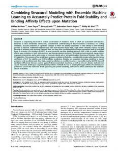
In the other version of the Panel state machine we have used a sub-state machine: GivePIN is defined as a separate state machine, and the OneCard state of the Panel state machine is a submachine state referring to the GivePIN state machine, see Figure 3-19 and Figure 3-20. The effect of the submachine state OneCard is as if the Panel state machine had a composite state with the contents of GivePIN. The benefit of submachine states is that the referenced state machine can be defined independently of the containing state machine. Reading four digits and producing a PIN is a rather general behavior and can be (re)used in other parts of the same containing state machine, or even in other state machines, as we have already observed in the corresponding interactions.
18
Chapter 3 sm Panel
Cardid(cid) NoCard
H OneCard: GivePIN
msg(t)/send(msg(t))
Figure 3-19. State machine Panel with submachine state according to GivePIN
sm GivePIN send(msg("Give your PIN!")); n=0 [n==4] digit/ send(code(cid,PIN)) enterDigit
waitCommand
Cardout [n