on the same host (Web) server with payload length 1460 bytes. (DARPA MIT dump). 1.2%. 1%. 1%. [132] normal HTTP traffic using ser- vices such as GET, ...
Desi gns& Algori thmsforPacketand ContentI nspecti on
Desi gns& Algori thms for Packetand ContentI nspecti on
I oanni sSourdi s
I oanni sSourdi s
Stellingen behorende bij het proefschrift / Propositions to the Ph.D. thesis
Designs & Algorithms for Packet and Content Inspection
van / by
Ioannis Sourdis
Delft, October 2007.
1. Informatie is het meest waardevol wanneer deze veilig in omloop wordt gebracht.
1. Information is most valuable when safely circulated. 2. Reconfigurable hardware is an efficient implementation platform for network security tasks that need to be frequently updated. 3. It is rare for a single packet to partially match more than a few tens of attack descriptions. 4. There are two ways to alleviate the tremendous needs of parallelism in network security: by either exploiting similarities among the descriptions or by filtering out the majority of them per piece of data. 5. Regular expressions are more efficient when implemented as NFAs in hardware and as DFAs in software than vice versa. 6. The difference between reconfigurable and reprogrammable is that the first can implement an arbitrary number of functions directly in hardware, while the second supports only a predefined -during fabrication- finite number of functions. An ALU is reprogrammable and not reconfigurable. – Stamatis Vassiliadis 7. Those that are able to spend more than 50% of their time doing research are most likely to be students. 8. People obey the gas law: they occupy as much space as they are given, and put pressure for more (– Dionisis Pnevmatikatos). Often, they behave similarly to gases in the opposite process: the more external pressure they get the more they resist and get high-“temp”. 9. [Part of a conversation between me and Stamatis Vassiliadis] Me: “. . . it’s not a shame not to know something.” Stamatis Vassiliadis: “It is a shame not trying to learn it!” 10. No matter how many times you read your thesis, on re-reading there is always another typo to correct or something else to chan ge. 11. There is no other meal more delicious than bread, tomato, and cheese, after hiking up a summer day at the top of Profitis Ilias (mountain) in Samos, Greece.
These propositions are considered defendable and as such have been approved by the promotor Prof. dr. K.G.W. Goossens.
2. Herconfigureerbare hardware is een effici¨ent implementatieplatform voor netwerkbeveiligingstaken die frequent vernieuwd moeten worden. 3. Het is voor een enkel pakket uitzonderlijk om gedeeltelijk overeen te komen met meer dan enkele tientallen beschrijvingen van aanvallen. 4. Er zijn twee oplossingen voor het verlichten van de enorme behoefte aan parallellisme in netwerk beveiliging: enerzijds door middel van uitnutten van gelijkheden in de beschrijvingen, anderzijds door uitfilteren van de meerderheid van de beschrijvingen per dataonderdeel. 5. Reguliere expressies zijn effici¨enter wanneer ge¨ımplementeerd als NFA’s in hardware en als DFA’s in software dan vice versa. 6. Het verschil tussen herconfigureerbaar en herprogrammeerbaar is dat de eerste een arbitrair aantal functies direct in hardware kan implementeren, terwijl de tweede slechts een vooraf gedefinieerd - tijdens productie - eindig aantal functies ondersteund. Een ALU is herprogrammeerbaar en niet herconfigureerbaar. – Stamatis Vassiliadis 7. Degenen die de mogelijkheid hebben om meer dan 50 procent van hun tijd aan onderzoek te besteden zijn met hoge waarschijnlijkheid studenten. 8. Mensen opereren gelijkend aan de natuurwet voor gassen: ze bezetten de ruimte die ze gegeven is en dringen aan op meer (– Dionisis Pnevmatikatos). Meestal gedragen ze zich ook gelijk aan gassen in het tegengestelde proces: hoe meer externe druk, hoe meer weerstand en hoe meer hun temperatuur oploopt. 9. [Deel van een gesprek tussen mij en Stamatis Vassiliadis] Ik: “. . . het is geen schande iets niet te weten.” Stamatis Vassiliadis: “het is een schande het niet te proberen te leren!” 10. Ongeacht hoe vaak je het proefschrift leest, bij elke keer is er altijd wel een schrijffout te corrigeren of iets anders te verander en. 11. Er is geen heerlijker maaltijd dan brood, tomaten en kaas na het beklimmen van de top van Profitis Ilias - berg in Samos, Griekenland - op een zomerdag. Deze stellingen worden verdedigbaar geacht en zijn als zodanig goedgekeurd door de promotor Prof. dr. K.G.W. Goossens.
Designs & Algorithms for Packet and Content Inspection Ioannis Sourdis
Designs & Algorithms for Packet and Content Inspection
PROEFSCHRIFT ter verkrijging van de graad van doctor aan de Technische Universiteit Delft, op gezag van de Rector Magnificus prof.dr.ir. J.T. Fokkema, voorzitter van het College voor Promoties, in het openbaar te verdedigen op dinsdag 18 december 2007 om 15:00 uur door
Ioannis SOURDIS electronic and computer engineer Technical University of Crete geboren te Corfu, Griekenland
Dit proefschrift is goedgekeurd door de promotors: Prof. dr. S. Vassiliadis† Prof. dr. K.G.W. Goossens Samenstelling promotiecommissie: Rector Magnificus, voorzitter Prof. dr. S. Vassiliadis†, promotor Prof. dr. K.G.W. Goossens, promotor Prof. dr. D.N. Pnevmatikatos Prof. dr. J. Takala Prof. dr. M. Valero Prof. dr.-Ing. J. Becker Prof. dr. ir. P.M. Dewilde Dr. K.L.M. Bertels Prof. dr. J.R. Long, reservelid
Technische Universiteit Delft Technische Universiteit Delft Technische Universiteit Delft Technical University of Crete Tampere University of Technology Technical University of Catalonia Universit¨at Karlsruhe Technische Universiteit Delft Technische Universiteit Delft Technische Universiteit Delft
CIP-DATA KONINKLIJKE BIBLIOTHEEK, DEN HAAG Sourdis, Ioannis Designs & Algorithms for Packet and Content Inspection Ioannis Sourdis. – Delft: TU Delft, Faculty of Elektrotechniek, Wiskunde en Informatica – Ill. Thesis Technische Universiteit Delft. – With ref. – Met samenvatting in het Nederlands.
Perilambnetai sÔnoyh sta Ellhnik. ISBN 978-90-807957-8-5
Cover page: “The Packet Inspector”, by Ioannis Sourdis, © 2007. Subject headings: Network Security, Intrusion Detection, Reconfigurable Packet Inspection, Pattern Matching, Perfect Hashing, Regular Expressions. Copyright © 2007 Ioannis SOURDIS All rights reserved. No part of this publication may be reproduced, stored in a retrieval system, or transmitted, in any form or by any means, electronic, mechanical, photocopying, recording, or otherwise, without permission of the author. Printed in The Netherlands
To my mentor Stamatis.
Sto dskalì mou Stamth.
Designs & Algorithms for Packet and Content Inspection Ioannis Sourdis
Abstract
T
his dissertation deals with essential issues pertaining to high performance processing for network security and deep packet inspection. The proposed solutions keep pace with the increasing number and complexity of known attack descriptions providing multi-Gbps processing rates. We advocate the use of reconfigurable hardware to provide flexibility, hardware speed, and parallelism in challenging packet and content inspection functions. This thesis is divided in two parts, firstly content inspection and secondly packet inspection. The first part considers high speed scanning and analyzing packet payloads to detect hazardous contents. Such contents are described in either static patterns or regular expression format and need to be matched against incoming data. The proposed static pattern matching approach introduces pre-decoding to share matching characters in CAM-like comparators and a new perfect hashing algorithm to predict a matching pattern. The FPGA-designs match over 2,000 static patterns, provide 2-8 Gbps operating throughput and require 10-30% area of a large reconfigurable device; that is half the performance of an ASIC and approximately 30% more efficient compared to previous FPGA-based solutions. The regular expression design is performed following a Non-Deterministic Finite Automata (NFA) approach and introducing new basic building blocks for complex regular expressions features. Theoretical grounds in support of the new blocks are established to prove their correctness. In doing so, approximately four times less Finite Automata states need to be stored. The designs achieve 1.6-3.2 Gbps throughput using 10-30% area of a large FPGA for matching over 1,500 regular expressions; that is 10-20× more efficient than previous FPGA-based works and comparable to ASICs. The second part of the thesis concerns offloading the overall processing of a packet inspection engine. Packet pre-filtering is introduced as a means to resolve or at least alleviate the processing requirements of matching incoming traffic against large datasets of known attacks. Partially matching descriptions of malicious traffic avoids further processing of over 98% of the attack descriptions per packet. Packet pre-filtering is implemented in reconfigurable technology and sustains 2.5 to 10 Gbps processing rates in a Xilinx Virtex2 device. i
Acknowledgements I would not have reached the point to complete my PhD if it was not for all my teachers I had since now; from the first, my parents as elementary-school teachers, to the most recent, my PhD advisor the late Prof.dr. Stamatis Vassiliadis. They taught me everything I know, or the way to learn it. I would like first and foremost to gratefully acknowledge them all. Normally, I would have dedicated my thesis to my family, my parents and my sister for their love and support, and to my girlfriend who I am so lucky I have met, for all her care and love. However, things sometimes (actually usually) do not go as planned. That is why only these lines are for them, to tell them how grateful I feel they are in my life. In Greek, so that my parents can read it:
Sa e�mai eugn¸mwn gia thn st rixh kai thn agph sa .
The one my thesis is dedicated to was supposed to be physically present at my defense, to strangle me a bit with his questions so that “arriving to Ithaca” would get sweeter. Now, I can only say I miss him very much, especially today! I feel privileged I had the chance to meet Stamatis Vassiliadis and spend three years under his mentorship. I am grateful for all the time he shared with me at work and also in personal life, for everything he taught me, for working all these late hours together, and for having all these wonderful dinners with us (his students). I have changed and I see some things differently after the past three years; that is mostly because of Stamatis. I am very proud I have been his student and more complete as a person I got to know his personal side. Although it is so obvious, without the help of the Rector Magnificus Prof.dr.ir. J.T. Fokkema and Dr. Georgi Gaydadjiev it would not be possible to officially have Prof.dr. Stamatis Vassiliadis as my promotor. I am grateful to both of them. Prof. Dionisis Pnevmatikatos was my MSc advisor, but he continues helping and advising me until now at every chance he has. His comments and suggestions have been always more than helpful, I deeply thank him for that and also iii
because, after all, the topic of this thesis was his initial suggestion. I would like to thank also Dr. Georgi Gaydadjiev and Dr. Koen Bertels for their help, support and encouragement the difficult past year and for putting all this effort and keep CE group together. Many thanks go to Prof.dr. Kees Goossens who significantly helped the last months of my PhD with his valuable comments that improved the quality of my thesis. Prof. Jarmo Takala helped very much by carefully reading my thesis and providing very detailed comments. Prof.dr. Mateo Valero also put significant amount of time -spare time he does not haveto provide comments on my thesis, I therefore would like to acknowledge him too. My life in Delft would have been less fun without my friends and colleagues. Roel and Maria have a special part of it, I thank them very much for their friendship, support and advice. I would also like to thank Barbara, Carlo, Christos, Christoforos, Daniele, Dimitris, Lotfi, Niki, Pepijn, Sebastian, Thodoris and the rest of the Greeks, Mediterraneans and others for all the fun we had during the past few years. It is always a pleasure to gather and have dinners together, like the old days with Stamatis. Roel and Christos get an extra acknowledgement for been “victimized” to proofread parts of my thesis. I am certainly fully responsible for any typos left. I also thank Pepijn for all the interesting discussions we had and for his help on translating my abstract and propositions in Dutch. Finally, I am thankful to Bert and Lidwina for their technical and administrative support, they definitely made my life simpler these years in the CE group.
Ioannis Sourdis
Delft, The Netherlands, 2007
iv
Contents Abstract
i
Acknowledgments
iii
List of Tables
ix
List of Figures
xi
List of Acronyms
xiv
1 Introduction
1
1.1
Deep Packet Inspection . . . . . . . . . . . . . . . . . . . . .
3
1.2
Problem Framework . . . . . . . . . . . . . . . . . . . . . .
5
1.3
Dissertation Objectives and Main Contributions . . . . . . . .
6
1.4
Dissertation overview . . . . . . . . . . . . . . . . . . . . . .
9
2 Intrusion Detection Systems
11
2.1
IDS Tasks . . . . . . . . . . . . . . . . . . . . . . . . . . . .
12
2.2
IDS Analysis . . . . . . . . . . . . . . . . . . . . . . . . . .
16
2.3
Implementation Platforms . . . . . . . . . . . . . . . . . . .
19
2.4
Conclusions . . . . . . . . . . . . . . . . . . . . . . . . . . .
22
3 Static Pattern Matching 3.1
23
HW-based Pattern Matching . . . . . . . . . . . . . . . . . .
v
25
3.1.1
CAM and Discrete Comparators . . . . . . . . . . . .
27
3.1.2
Regular Expressions . . . . . . . . . . . . . . . . . .
28
3.1.3
Hashing . . . . . . . . . . . . . . . . . . . . . . . . .
29
3.1.4
Other Algorithms . . . . . . . . . . . . . . . . . . . .
32
3.1.5
ASICs . . . . . . . . . . . . . . . . . . . . . . . . . .
33
Pre-decoded CAM . . . . . . . . . . . . . . . . . . . . . . .
33
3.2.1
Performance Optimization . . . . . . . . . . . . . . .
36
3.2.2
Area Optimization . . . . . . . . . . . . . . . . . . .
39
Perfect Hashing Memory . . . . . . . . . . . . . . . . . . . .
39
3.3.1
Perfect Hashing Tree . . . . . . . . . . . . . . . . . .
40
3.3.2
PHmem Basic Building Function . . . . . . . . . . .
44
3.3.3
Proof of PHmem Correctness . . . . . . . . . . . . .
47
3.3.4
Theoretical Analysis of the PHmem Algorithm . . . .
49
3.3.5
Pattern Pre-processing & Implementation Issues . . .
54
3.3.6
PHmem Implementation in ASIC . . . . . . . . . . .
57
Evaluation . . . . . . . . . . . . . . . . . . . . . . . . . . . .
57
3.4.1
DCAM Evaluation . . . . . . . . . . . . . . . . . . .
58
3.4.2
PHmem Evaluation . . . . . . . . . . . . . . . . . . .
61
3.4.3
Memory-Logic Tradeoff . . . . . . . . . . . . . . . .
62
3.4.4
Scalability
. . . . . . . . . . . . . . . . . . . . . . .
63
3.5
Comparison . . . . . . . . . . . . . . . . . . . . . . . . . . .
64
3.6
Conclusions . . . . . . . . . . . . . . . . . . . . . . . . . . .
67
3.2
3.3
3.4
4 Regular Expression Matching
69
4.1
Regular Expressions in IDS . . . . . . . . . . . . . . . . . . .
72
4.2
Related Work . . . . . . . . . . . . . . . . . . . . . . . . . .
75
4.3
Regular Expressions Engine . . . . . . . . . . . . . . . . . .
77
4.3.1
Basic NFA blocks
. . . . . . . . . . . . . . . . . . .
77
4.3.2
Area Optimizations . . . . . . . . . . . . . . . . . . .
85
4.3.3
Performance Optmizations . . . . . . . . . . . . . . .
86
Synthesis Methodology . . . . . . . . . . . . . . . . . . . . .
86
4.4
vi
4.5
Evaluation . . . . . . . . . . . . . . . . . . . . . . . . . . . .
90
4.6
Comparison . . . . . . . . . . . . . . . . . . . . . . . . . . .
96
4.7
Conclusions . . . . . . . . . . . . . . . . . . . . . . . . . . . 100
5 Packet Prefiltering
101
5.1
Related Work . . . . . . . . . . . . . . . . . . . . . . . . . . 104
5.2
Packet Prefiltering . . . . . . . . . . . . . . . . . . . . . . . . 105
5.3
Integrating Packet Pre-filtering . . . . . . . . . . . . . . . . . 112
5.4
Analysis . . . . . . . . . . . . . . . . . . . . . . . . . . . . . 116
5.5
Experimental Results . . . . . . . . . . . . . . . . . . . . . . 121
5.6
5.5.1
Simulation Results . . . . . . . . . . . . . . . . . . . 121
5.5.2
Implementation Results . . . . . . . . . . . . . . . . 130
Conclusions . . . . . . . . . . . . . . . . . . . . . . . . . . . 133
6 Conclusions
135
6.1
Summary . . . . . . . . . . . . . . . . . . . . . . . . . . . . 136
6.2
Contributions . . . . . . . . . . . . . . . . . . . . . . . . . . 138
6.3
Proposed Research Directions . . . . . . . . . . . . . . . . . 140
Bibliography
143
List of Publications
157
Samenvatting
161
SÔnoyh
163
(Synopsis in Greek)
Curriculum Vitae
165
vii
List of Tables 1.1
Worldwide Economic Impact of Network Attacks 1997-2006 (in billion U.S. $) [1, 2]. . . . . . . . . . . . . . . . . . . . . .
2
2.1
Snort-PCRE basic syntax. . . . . . . . . . . . . . . . . . . . .
15
2.2
Current SNORT syntax features which make IDS tasks more computationally intensive. . . . . . . . . . . . . . . . . . . .
16
2.3
Profiling Snort IDS [3–6]. . . . . . . . . . . . . . . . . . . . .
17
2.4
Characteristics of various Snort rulesets, number of rules, number of unique static patterns and number of unique regular expressions. . . . . . . . . . . . . . . . . . . . . . . . . . . .
18
3.1
Perfect Hash Tree algorithm - main process. . . . . . . . . . .
42
3.2
Basic Building function of the Perfect Hashing algorithm. . . .
45
3.3
Hash trees evaluation. . . . . . . . . . . . . . . . . . . . . . .
61
3.4
Comparison of FPGA-based pattern matching approaches. . .
66
4.1
Regular expressions characteristics used in Snort and Bleeding Edge rulesets. . . . . . . . . . . . . . . . . . . . . . . . . . .
73
4.2
The basic building blocks of our Regular Expression Engine. .
78
4.3
Generation and Implementation times for Snort and Bleeding rulesets of Oct.’06. . . . . . . . . . . . . . . . . . . . . . . .
89
Comparison between our RegExp Engines and other HW regular expression approaches. . . . . . . . . . . . . . . . . . . .
99
4.4
5.1
Most frequent characters in normal traffic traces. . . . . . . . 119
5.2
Packet Pre-filtering Area Cost. . . . . . . . . . . . . . . . . . 130 ix
List of Figures 1.1
Wide area and Last mile network bandwidth growth vs. computing power of single chip processors. . . . . . . . . . . . . .
3
A Network Intrusion Detection System consists of several preprocessors and the detection engine. . . . . . . . . . . . . . .
5
2.1
NIDS decomposition and IDS rule example. . . . . . . . . . .
13
2.2
Performance-Flexibility tradeoff between different IDS implementation solutions. . . . . . . . . . . . . . . . . . . . . . . .
19
Abstract illustration of performance and area efficiency for various static pattern matching approaches. . . . . . . . . . .
26
3.2
Basic CAM discrete comparator structure and optimization. . .
34
3.3
Pre-decoded CAM (DCAM). . . . . . . . . . . . . . . . . . .
35
3.4
DCAM processing two characters per cycle. . . . . . . . . . .
36
3.5
The DCAM structure of an N -search pattern module with parallelism P = 4. . . . . . . . . . . . . . . . . . . . . . . . . .
37
3.6
DCAM with Multiple Clock Domains. . . . . . . . . . . . . .
38
3.7
Partial Matching of long patterns in DCAM. . . . . . . . . . .
39
3.8
Perfect Hashing memory block diagram. . . . . . . . . . . . .
41
3.9
Perfect Hash trees: the select of each multiplexer is a function generated by the SUB HASH. . . . . . . . . . . . . . . . . . .
43
3.10 An example of using SUB HASH to split a Set in two subsets which require one bit less to be encoded compared to the set. .
47
3.11 Worst case number of operations required to generate a Perfect Hash Tree for various sets of patterns. . . . . . . . . . . . . .
52
1.2
3.1
xi
3.12 Perfect Hash Tree Cost in 4-input gates of various pattern sets.
55
3.13 An example of storing patterns in the PHmem pattern memory.
56
3.14 Comparison between the Discrete Comparator CAM and the DCAM architectures. . . . . . . . . . . . . . . . . . . . . . .
59
3.15 PHmem and DCAM performance, area cost, and efficiency. . .
60
3.16 PHmem and DCAM scalability. . . . . . . . . . . . . . . . .
63
3.17 Normalized Performance Efficiency Metric of PHmem, DCAM and related work. . . . . . . . . . . . . . . . . . . . .
65
4.1
NFA and DFA representations of the regular expressions (x|y) ∗ x{2} and (x|y) ∗ y(x|y){n} (for n=2). The second example illustrates the DFA state explosion. . . . . . . . . . .
71
Characteristics of Snort rulesets regarding the regular expressions. . . . . . . . . . . . . . . . . . . . . . . . . . . . . . .
74
Distribution of two of the most commonly used constrained repetitions in Snort IDS, type Exactly and AtLeast. Results are for the Snort v2.4 Oct. 2006 version. . . . . . . . . . . . .
74
4.4
Block diagram of our Regular Expression Engines. . . . . . .
76
4.5
The Exactly block: a{N }. . . . . . . . . . . . . . . . . . . .
79
4.6
The AtLeast block: a{N, }. . . . . . . . . . . . . . . . . . . .
80
4.7
The Between block: a{N, M } = a{N }a{0, M − N }. . . . .
82
4.2 4.3
b+ [∧ \n]{2}.
4.8
An implementation for the regular expression
. .
84
4.9
Proposed methodology for generating regular expressions pattern matching designs. . . . . . . . . . . . . . . . . . . . . .
87
4.10 Hierarchical decomposition or the regular expression “∧ CEL \ s[∧ \n]{100, }”. . . . . . . . . . . . . . . . . . . .
89
4.11 Area cost of the constrained repetitions blocks. . . . . . . . .
91
4.12 Area and performance improvements when applying a stepby-step optimization for three different IDS rulesets. . . . . .
93
5.1
The effect of packet pre-filtering in a sequential and a parallel IDS processing model. . . . . . . . . . . . . . . . . . . . . . 102
5.2
The Packet Pre-filtering block diagram. Packet pre-filtering is customized based on the IDS ruleset at hand. . . . . . . . . . 107 xii
5.3
Pipelined priority encoder implementation details. . . . . . . . 109
5.4
An example of the pipelined priority encoder. . . . . . . . . . 110
5.5
Packet pre-filtering alternatives.
5.6
PINE: Packet INspection Engine. A Reconfigurable Intrusion Detection Engine utilizing packet pre-filtering. . . . . . . . . . 115
5.7
Probability for a packet to activate more than 32 or 64 rules 1 considering random traffic, c = 256 . . . . . . . . . . . . . . . 117
5.8
Probability for a packet to activate more than 32 or 64 rules considering that all prefix characters used in prefiltering have 10% or 6% probability to be found. The payload size is between 512 bytes to 1 Mbyte. . . . . . . . . . . . . . . . . . . 118
5.9
Probability for a packet to activate more than 32 or 64 rules considering that all prefix characters used in prefiltering have c = 10% probability to be found and the payload size is very long (1-256 Mbytes). . . . . . . . . . . . . . . . . . . . . . . 120
. . . . . . . . . . . . . . . . 111
5.10 Packet trace statistics: number of packets that include payload and header-only packets in Defcon11 traces. . . . . . . . . . . 122 5.11 Cumulative distribution of payload pattern length in the SNORT rules. . . . . . . . . . . . . . . . . . . . . . . . . . . 122 5.12 Average number of candidate rules per packet after the prefiltering step as a function of the pre-filtering length. . . . . . 123 5.13 Maximum number of candidate rules per single incoming packet after the pre-filtering step as a function of the prefiltering length (length 2 was omitted for clarity due to exceedingly large values). . . . . . . . . . . . . . . . . . . . . . . . 124 5.14 The average number of activated rules per packet when matching different portions of the rules in the pre-filtering stage. . . 126 5.15 The maximum number of activated rules per packet when matching different portions of the rules in the pre-filtering stage. 127 5.16 Comparison of the average number of activated rules per incoming packet when choosing different prefix lengths and different parts of the rules to be included in the prefiltering . . . . 128 5.17 Comparison of the maximum number of activated rules per incoming packet when choosing different prefix lengths and different parts of the rules to be included in the prefiltering . . 128 xiii
List of Acronyms ALU ASIC bps CAM CPU DCAM DFA DPI DoS ELC FA FF FLOPS FPGA FSM FTP GPP HDL HTTP ICMP IP LUT NFA NIDS NIPS NP PCRE PEM PHmem PLA RPC RegExpr SMTP TCAM TCP UDP WAN
Arithmetic Logic Unit Application-Specific Integrated Circuit bits per second Content Addressable Memory Central Processing Unit Decoded CAM Deterministic Finite Automaton Deep Packet Inspection Denial of Service Equivalent Logic Cells Finite Automaton Flip-Flop Floating point Operations Per Second Field Programmable Gate Array Finite State Machine File Transfer Protocol General Purpose Processor Hardware Description Language Hyper Text Transfer Protocol Internet Control Message Protocol Internet Protocol Look Up Table Non-deterministic Finite Automaton Network Intrusion Detection System Network Intrusion Prevention System Network Processor Perl-Compatible Regular Expressions Performance Efficiency Metric Perfect-Hashing Memory Programmable Logic Array Remote Procedure Call Regular Expression Simple Mail Transfer Protocol Ternary Content Addressable Memory Transmission Control Protocol User Datagram Protocol Wide Area Network xiv
Digital information is most valuable when safely circulated
Chapter 1
Introduction
T
he proliferation of Internet and networking applications, coupled with the wide-spread availability of system hacks and viruses, urges the need for network security. The security of digital information systems has an increasing impact on modern societies and economies. Information is most valuable when (safely) circulated and hence, network security is a critical issue with great financial impact and significant effect on society. Private industries in finance, trade, services, transportation, manufacturing, and public sectors such as medical, vital services, national economy, defense and intelligence depend on computing systems. Consequently, any information and network security failure of these systems may often result in significant economic damage or disasters. Recent analyses show the economic impact of network security. It is estimated that worldwide digital attacks cost billions of US dollars every year [1, 2]. As depicted in Table 1.1, Computer Economics Inc. estimates that approximately 13-17 billion dollars are lost every year due to network attacks [1]. Another analysis by the British company Mi2g indicates that the annual economic cost is up to hundreds of billion dollars [2]. In either case, sophisticated network security systems are necessary for modern societies and economic prosperity. The growing gap between network bandwidth requirements and available computing power [7] imposes severe limitations to existing network security systems. Gilder identified a gap between network bandwidth and computing power [7]. On one hand, technological advances (still) allow transistor count to (presumably) double every eighteen months [8]. On the other hand, it has been postulated that network bandwidth doubles every six months. Assuming that increase in transistor count indicates computing power improvement, 1
2
C HAPTER 1. I NTRODUCTION
Table 1.1: Worldwide Economic Impact of Network Attacks 1997-2006 (in billion U.S. $) [1, 2].
Year Computer Economics [1] 2006 13.3 2005 14.2 2004 17.5 2003 13.0 2002 11.1 2001 13.2 2000 17.1 1999 13.0 1998 6.1 1997 3.3 Sources: Computer Economics [1] and Mi2g [2]
Mi2g [2] NA NA NA 185-226 110-130 33-40 25-30 19-23 3.8-4.7 1.7-2.9
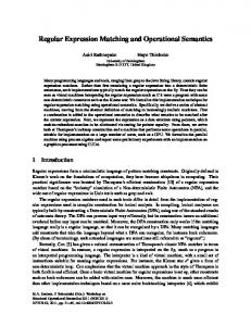
network bandwidth grows three times faster than computing power. Under the conjectures stated above it can be indicated that network processing gets more computationally intensive. Increasingly higher network processing performance is required than the computing systems may provide. The graph of Figure 1.1 shows the above point in practice. Network line rates rapidly grow by a factor of 2-4× per year, while computing power has a constant improvement of no more than 1.6× per year. In the last twenty years, wide area network (WAN) bandwidth has increased from a few hundreds Kbits per second to tens of Gbps. WAN bandwidth quadruples every year verifying Gilder’s claim. The “last mile” network bandwidth follows WAN growth with a delay of a few years. Although, until recently, last mile network bandwidth was increasing about 1.5× per year, recent advances in fiber optics technology allow a 2-4× growth in the coming years. On the contrary, computing power increases up to 1.6× per year. Figure 1.1 depicts the computing power of single-chip processors over the past two decades measured in million floating point operations per second (MFLOPS). An Intel 80486 in the early 90’s could perform 3.48 MFLOPS, a Pentium III in 1999 145 MFLOPS, while a Core 2 Duo of 2006 can execute 508 MFLOPS. After the year 2000 there is an increasing gap between network bandwidth and computing power, small but already evident for the “last mile” networks and substantially larger for WAN. In summary, the economic and social impact of information security coupled
1.1. D EEP PACKET I NSPECTION Single chip computing power FLOPS
3 Last Mile bandwidth bits/sec
Wide Area Network bandwidth bits/sec
106 10
5
10
4
10 Gbps
622Mbps
22 Mbps
310 Mbps
155 Mbps
2
101
256 Kbps
14.4 Kbps 1.5 Mbps
80486 3.48 MFlops 0
10
Last Mile 1.5-4x/year 50-100 Mbps
2.5 Gbps
103 10
WAN 4x/year
40 Gbps
1990
Pent 33.7 PentPro MFlops 41.5 MFlops 2 Mbps Pent
28.8 Kbps
1995
20 Mbps P3 12 Mbps P2
56 Kbps
4 Mbps
384 Kbps
2000
1.55 Mbps P4
P4 P3 Tualatin 248 MFlops
4 Mbps
Pent M 392 MFlops
2005
Computing 1.4-1.6x/year
Core 2 Duo 1CP 508 MFlops
2010
Figure 1.1: Wide area and Last mile network bandwidth growth vs. computing power of single chip processors. All values in the graph have been normalized to their initial value of 1990.
with the increasing network processing requirements impose the need for efficient and effective network security solutions. These solutions should provide high performance at reasonable cost, flexibility, and scalability in order to keep up with current and future network security needs. The above sketch the challenges addressed in this thesis. The remaining of this introductory chapter is organized in four sections. Section 1.1 provides a brief description of Deep Packet Inspection, an efficient solution for network security. Section 1.2 draws the problem framework of this dissertation. Section 1.3 presents the thesis objectives outlining the dissertation scope and describes the main contributions. Finally, Section 1.4 overviews the remaining contents of the dissertation.
1.1 Deep Packet Inspection High speed and always-on network access is commonplace around the world creating a demand for more sophisticated packet processing and increased network security. The answer to this sophisticated network processing and network security can be provided by Deep Packet Inspection (DPI) [9]. In essence, deep packet inspection is able to accurately classify and control traf-
4
C HAPTER 1. I NTRODUCTION
fic in terms of content and applications. In other words, it analyzes packets content and provides a content-aware processing. The most challenging task in DPI is content inspection, since the body (payload) of each packet needs to be scanned [3, 4]. In general, DPI systems should provide the following: • high processing throughput, • low implementation cost, • flexibility in modifying and updating the content descriptions, and • scalability as the number of the content descriptions increases. The above goals become more difficult to achieve due to two reasons. First, the gap between network bandwidth and computing power is growing [7]. Second, the database of known attack patterns becomes larger and more complex. Currently, several network functions need a more efficient analysis and information about the content and the application data of the processing packets. DPI is used in network applications such as: • Network Intrusion Detection/Prevention Systems: As opposed to traditional firewalls, NIDS/NIPS scan the entire packet payload for patterns that indicate hazardous content. A combination of packet classification (header matching) and content inspection is used to identify known attack descriptions. Previous techniques such as stateful inspection are still required to provide efficient security. • Layer 7 Switches1 : authentication, load balancing, content-based filtering, and monitoring are some of the features that layer 7 switches support. For example application aware web switches provide transparent and scalable load balancing in data centers. • Traffic Management and Routing: Content-based routing and traffic management may differentiate traffic classes based on the application data. This dissertation addresses the above Deep Packet Inspection challenges focussing on DPI for Network Security (NIDS/NIPS). Although, the principles 1
A network device that integrates routing and switching by forwarding traffic at layer 2 speed using layer 7 (application layer) information. Also known as content-switches, content-service switches, web-switches or application-switches.
1.2. P ROBLEM F RAMEWORK
5
Network Intrusion Detection System PreProcessors Reassembly & Reorder Stateful Inspection
Detection Engine Search for known attack patterns
Decoding
Packet Classification/ Header matching Content Inspection/ pattern matching
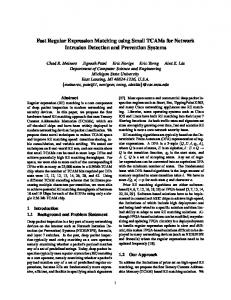
Figure 1.2: A Network Intrusion Detection System consists of several preprocessors and the detection engine. Preprocessors are related to packet reassembly and reordering, stateful inspection and several decoding schemes. The detection engine is the NIDS core which scans each packet against various attack patterns. This thesis aims at improving and accelerating the most computationally intensive NIDS part, the detection engine.
followed in all DPI network applications remain unchanged, we can note that in NIDS2 the content descriptions may be more complex and more in number, creating significant performance limitations and implementation difficulties compared to other network applications such as content-aware traffic management and switching.
1.2 Problem Framework Like most networking systems, a network intrusion detection system requires complex interfaces and functions to handle network protocols and keep track of multiple flows. Some of these functions may be of significant research interest while others are just implementation details. Building a complete NIDS is not within this thesis scope. We provide a NIDS decomposition and describe below the framework of the problem addressed in the thesis. Figure 1.2 illustrates an abstract block diagram of a network intrusion detection system. A NIDS consists of two main parts, the preprocessors and the detection engine. There are several preprocessors that perform reassembly and 2
For the rest of the dissertation by NIDS we mean both NIDS and NIPS
6
C HAPTER 1. I NTRODUCTION
reordering of TCP packets, stateful inspection functions, and various packet decodings. After the preprocessing phase comes the main detection engine which examines incoming traffic against known attack patterns. The NIDS detection engine is the core of the system. It performs packet classification (header matching) and content inspection (payload pattern matching) using multiple packet header and the payload descriptions of malicious traffic. Currently NIDS databases, denoted also as rulesets in the rest of the thesis, contain thousands of attack descriptions each one possibly using complex and/or long payload patterns. It is worth noting that the NIDS detection engine requires up to 85% of the total execution time when running in a GPP, while pattern matching alone takes about 30-80% of the total processing (Chapter 2). Existing systems support moderate performance limited to a few hundred Mbits per second (Mbps) and often compromise accuracy. Abstracting the NIDS implementation details and the preprocessors tasks, the focus of this dissertation turns to the NIDS detection engine. The basic aim is to accelerate the content inspection and reduce the overall required processing of the NIDS detection engine. The proposed solutions should further provide flexibility and scalability in order to satisfy the increasing needs of network security.
1.3 Dissertation Objectives and Main Contributions In this dissertation, we focus on deep packet inspection with emphasis on improving the efficiency of the required content inspection and minimizing the packet processing load. We are particularly interested in Network Intrusion Detection Systems due to the complex and computationally demanding content descriptions used to identify hazardous packets. To solve the performance problems regarding the execution of NIDS on GPPs and other existing platforms, we propose reconfigurable computing supporting the specific computational requirements of the NIDS. As identified in Section 1.2, current proposals suffer from a number of drawbacks, which have been resolved or substantially alleviated by the techniques presented here3 . We discuss below the objectives that determine the scope of this dissertation, and the main thesis contributions: • Augment the benefits of reconfigurable hardware for DPI: As mentioned earlier, Intrusion Detection Systems (NIDS) should sustain high 3 A detailed discussion on how such drawbacks are resolved is presented in Chapters 3, 4, and 5.
1.3. D ISSERTATION O BJECTIVES
AND
M AIN C ONTRIBUTIONS
7
processing throughput and provide the flexibility of updating mechanisms in order to renew and improve their rulesets. It is a well known fact that, NIDS running in GPP cannot support a throughput higher than a few hundreds of Mbps [10]. In this dissertation we advocate the use of reconfigurable hardware as the implementation platform of a NIDS. Reconfigurable technology is able to provide the required flexibility to modify the system when needed, while the fast (hardware) processing rates can be achieved exploiting specialized circuitry and parallelism. The proposed solutions are designed and implemented for reconfigurable technologies. In addition, we follow a methodology of automatically generating the HDL description of the designs for a given ruleset in order to improve flexibility and speed up the system update. Chapters 3, 4, and 5 provide implementation results in reconfigurable hardware for every proposed design. • Address the problem of static\explicit pattern matching for NIDS: Content inspection is the most computationally intensive task in NIDS. Matching static payload strings, in other words the literal meaning of patterns, is one of the two content inspection tasks4 . Pattern matching should be performed in high-speed at the lowest possible implementation cost. We address the above issue presenting two static pattern matching techniques. The first one is Decoded CAM (DCAM) and uses logic to match the search patterns and exploits pattern similarities. The second approach Perfect Hashing Memory (PHmem) utilizes a new perfect hashing technique to hash the incoming data and determine the location of a single pattern that may match. The proposed designs match thousands of IDS patterns and support 2-8 Gbps throughput. Chapter 3 presents the two methods in detail. • Address the problem of regular expression pattern matching for NIDS: Regular expressions is a more advanced way to describe hazardous contents in NIDS and more challenging to implement. Regular expression matching should also support high processing throughput at the lowest possible implementation cost. There are several significant issues in regular expression pattern matching that make their implementation difficult in both software and hardware. On the one hand, Deterministic Finite Automata (DFA) implementations suffer from state explosion, on the other hand, Non-deterministic Finite Automata (NFA) have limited performance, while complicated syntax features such as 4
The other content inspection task is regular expression matching.
8
C HAPTER 1. I NTRODUCTION
constrained repetitions require significant amount of resources. We address the above providing a solution in Chapter 4. The proposed NFA approach achieves 1.6-3.2 Gbps throughput and saves three quarters of the required NFA states. • Compare the proposed content inspection techniques against existing related work: It is essential to compare the proposed content inspection techniques against related work. It is also important to have a metric that measures the efficiency of each solution. We evaluate every content inspection design in terms of performance (throughput) and area cost. A Performance Efficiency Metric (PEM) is utilized to measure the efficiency of the designs. It is actually the achieved throughput of a design over its implementation cost. At the end of Chapters 3 and 4 we present a detailed comparison between related works and the proposed content inspection designs. Our static pattern matching approach achieves half the performance of an Application-Specific Integrated Circuit (ASIC) and is about 30% more efficient than previous FPGA-based solutions. Our regular expression designs are 10-20× more efficient than previous FPGA works and comparable to ASIC DFA implementations. • Solve Deep Packet Inspection computational complexity problems: As discussed earlier, the network bandwidth requirements increase faster than the offered computing capabilities. Currently, NIDS require multiGigabit/sec throughput while their rulesets grow rapidly. The first dissertation objective aims at reducing the NIDS computational requirements. In addition, performance should be maintained, despite the fact that NIDS rulesets become larger and more complex. As a means to resolve, or at least alleviate, the increasing computational needs of high speed intrusion detection systems, a technique called packet pre-filtering is introduced. Packet pre-filtering is able to exclude from further processing the majority of the rules per incoming packet and thus reduce the required overall NIDS processing. In our experiments, packet prefiltering leaves only a few tens of IDS rules per packet (out of thousands) to be entirely matched. The FPGA implementation of the algorithm sustains 2.5-10 Gbps throughput. Packet pre-filtering is extensively covered in Chapter 5. • Address Scalability Issues of the NIDS tasks: NIDS rulesets become increasingly larger as they are constantly updated with new attack descriptions. In addition, their rule syntax becomes more complex in order to express hazardous contents more efficiently. As a consequence, any
1.4. D ISSERTATION
OVERVIEW
9
proposed solution for content inspection or a complete packet inspection engine should be able to scale well in terms of performance and implementation cost as the NIDS ruleset grows and becomes more complicated. All the content inspection solutions of Chapters 3 and 4 are evaluated as the content descriptions increase and show that their performance and implementation cost scale well as the ruleset becomes larger. In addition, the proposed packet pre-filtering technique in Chapter 5 aims, among others, at improving the scalability of the packet inspection engine. An overview of how the research objectives have been attained and how they are presented in this dissertation follows.
1.4 Dissertation overview The thesis consists of three parts: The first part offers a background analysis of Intrusion Detection Systems, covered in Chapter 2. The second part, covered in Chapters 3 and 4, deals with the most computationally intensive NIDS task, content inspection. Chapters 3 and 4 present pattern matching and regular expression matching techniques, respectively, for NIDS. The third part is Chapter 5, and describes a general solution for the computational complexity and scalability of DPI. More precisely, the remainder of the dissertation is organized as follows: Chapter 2 provides some background information and a concise description of network intrusion detection systems. We describe the structure of the NIDS rules and explain the main NIDS tasks. Furthermore, we identify the most challenging and computationally intensive IDS tasks that substantially diminish performance. Finally, we discuss the alternative NIDS implementation platforms analyzing their tradeoffs. As mentioned earlier the most computational intensive NIDS task is content inspection. NIDS rules use widely static patterns and regular expressions to describe hazardous payload contents. Consequently, static pattern matching is one of the two major content inspection functions. Chapter 3 describes two new static pattern matching techniques to examine incoming packets against the intrusion detection search patterns. The first approach, DCAM, pre-decodes incoming characters, aligns the decoded data and performs a logical AND to produce the match signal for each pattern. The second approach, PHmem, introduces a new perfect hashing technique to access a memory that
10
C HAPTER 1. I NTRODUCTION
contains the search patterns and a simple comparison between incoming data and memory output determines the match. It is proven, that PHmem guarantees a perfect hash generation for any given set of patterns. Additionally, a theoretical analysis shows the PHmem generation complexity and the worst case implementation cost of the perfect hash function. Both approaches are implemented in reconfigurable hardware. We evaluate them in terms of performance and area cost, compare them with related works and analyze their efficiency, scalability and tradeoffs. The second content inspection function, regular expression matching, is discussed in Chapter 4. A Nondeterministic Finite Automata (NFA) approach is introduced for reconfigurable hardware. The proposed solution introduces three new basic building blocks to support more complex regular expression descriptions than the previous approaches. Theoretical grounds supporting the new blocks are established to prove their correctness. The suggested methodology is supported by a tool that automatically generates the circuitry for the given regular expressions. The proposed technique is implemented and evaluated in reconfigurable technology, while the generated designs are compared against related works. Chapter 5 presents a new technique called packet pre-filtering to address the increasing processing needs of current and future intrusion detection systems. Packet pre-filtering lends itself to both software and hardware implementations. It selects a small portion from each IDS rule to be matched. The result of this partial match is only a small number of rules per packet that are activated for further processing. This way, we reduce the overall required NIDS processing. A theoretical analysis and a real traffic trace-driven evaluation show the effectiveness of packet pre-filtering. Moreover, the technique has been designed for reconfigurable hardware and implementation results are reported. Finally, concluding remarks are presented in Chapter 6. The chapter summarizes the dissertation, outlines its contributions and suggests future research directions.
Chapter 2
Intrusion Detection Systems
F
irewalls have been used extensively to prevent access to systems from all but a few, well defined access points (ports), but they cannot eliminate all security threats nor can they detect attacks when they happen. Stateful inspection firewalls are able to understand details of the protocol that are inspecting by tracking the state of a connection. They actually establish and monitor connections until they are terminated. However, current network security needs, require a much more efficient analysis and understanding of the application data [9]. Content-based security threats and problems occur more frequently, in an every day basis. Virus and worm inflections, SPAMs (unsolicited e-mails), email spoofing, and dangerous or undesirable data, get more and more annoying and cause innumerable problems. Therefore, next generation firewalls should support Deep Packet Inspection properties, in order to provide protection from these attacks. Network Intrusion Detection Systems (NIDS) are able to support DPI processing and protect an internal network from external attacks1 . NIDS check the packet header, rely on pattern matching techniques to analyze packet payload, and make decisions on the significance of the packet body, based on the content of the payload. This Chapter provides some background information regarding Intrusion Detection Systems. The remaining of the Chapter is organized as follows: Section 2.1 gives an overview of NIDS tasks focusing on the features of the NIDS rules. Section 2.2 analyzes the profile of the widely used open source NIDS Snort [11, 12] and points out the most challenging NIDS parts. Finally, in Section 2.3 we discuss alternative implementation platforms for NIDS. 1
Depending on the NIDS placement, a NIDS may monitor also internal traffic detecting intrusions that might have already affected parts of the protected network.
11
12
C HAPTER 2. I NTRUSION D ETECTION S YSTEMS
2.1 IDS Tasks As briefly described in Chapter 1.2, Intrusion Detection Systems (IDS) use several preprocessors and a ruleset-based detection engine which performs packet classification and content inspection. Figure 2.1 illustrates a breakdown of an intrusion detection system. It is worth noting that the described IDS generates per packet alerts and subsequently correlations between multiple alerts may indicate a complete attack plan [13–15]. An IDS rule such as the ones of Snort [12] and Bleeding [16] open source IDS, consists of a header matching part and a payload matching part. The first one checks the header of each incoming packet using packet classification techniques. The second examines the payload of each packet performing content inspection. Content Inspection involves matching packet payload against predefined patterns either described as static patterns or regular expressions. Additional restrictions concerning the placement of the above patterns introduce further complexity to the processing of the IDS tasks. Below, each IDS task is discussed in detail. Preprocessors: The IDS preprocessors implement the necessary functions that allow the subsequent detection engine to correctly examine incoming traffic against predefined attack descriptions. Preprocessors are responsible for three kinds of tasks. First, they reassemble and reorder TCP packets into larger ones. This is necessary in order to detect attacks that span across multiple packets. Second, they perform stateful inspection functions such as flow tracking or portscan detection; that is, functions related to the protocol level that keep track of different connections/flows. Stateful inspection can also be seen as a module which has an overview of the traffic -at a higher level than the content inspection- checking for abnormal events such as buffer overflows or Denial of Service (DoS) attacks. Third, preprocessors perform specialized inspection functions, mostly decoding of various kinds of traffic, e.g., Telnet, FTP, RPC, HTTP, SMTP, packets with malicious encodings, etc. After the preprocessors comes the detection engine which uses a rule database (ruleset) to describe malicious packets. Each rule has a packet classification and a content inspection part. Furthermore, content inspection includes static pattern matching, regular expression matching and pattern placement restrictions. Packet Classification: The header part of each NIDS rule describes the header of a potentially dangerous packet. As depicted in Figure 2.1, the header description may consist of some or all the following: Protocol, Destination IP and Port and Source IP and Port. The IP and Port fields of a rule may spec-
2.1. IDS TASKS
13
PreProcessors
Reassembly & Reorder
Stateful Inspection
Detection Engine ruleset rule1 rule2 rule3 rule4
ruleN
Decoding
Header Matching part alert Protocol Dest IP/Port -> Src IP/Port (content:"Static Pattern"; pcre:"/Regural Expression/i"; within:10;) Payload part
Example of IDS rule: alert tcp $EXTERNAL_NET any -> $HOME_NET 80 (content:"ATTACK"; pcre:"/^PASS\s*\n/smi"; within:10;)
Figure 2.1: NIDS decomposition. Incoming traffic is scanned first by a series of preprocessors that perform packet reordering and reassembly, stateful inspection and decoding of specific kinds of traffic. Subsequently, packets are examined against rules that describe malicious activity. Each rule has a packet header and payload description. An example of IDS rule is depicted at the right bottom part of the Figure.
ify ranges of values instead of a specific address or port. This makes packet classification more challenging than a simple comparison of numerical values. Many researchers in the past have proposed different techniques for packet classification and IP lookup such as [17–19], while some of them also use reconfigurable hardware [20–22]. In this thesis and particularly in Chapter 5 we use the method proposed in [23] and implement simple comparators to match the specified addresses or ranges of addresses and ports. This method achieves high performance and fits well within the proposed reconfigurable designs. Static Pattern Matching: Matching the literal meaning of predefined (static) patterns is certainly the most significant IDS task. Static patterns are used to describe malicious payload contents and provide an insight of the packet application data. An IDS rule may contain one or more static patterns of a few bytes up to several hundreds of bytes long. Figure 2.1 illustrates an IDS-rule example which contains a static pattern. The static pattern ATTACK is indicated as a malicious payload pattern using the statement: content:"ATTACK". Matching thousands of payload patterns in parallel per incoming packet creates fundamental difficulties in IDS performance. Initially, IDS systems described
14
C HAPTER 2. I NTRUSION D ETECTION S YSTEMS
malicious contents only with static patterns, however, recently they started using both static patterns and regular expressions. Regular Expression Matching: We next discuss the regular expressions used in IDS packet payload scanning. More precisely, we describe the features of the regular expressions included in Snort and Bleeding Edge IDS. Snort and Bleeding Edge open source IDS [12, 16], used in the remainder of this thesis, adopted the Perl-compatible regular expression syntax (PCRE) [24]. The IDS rule example of Figure 2.1 uses the statement pcre:"/∧PASS\s*\n/smi"; to describe malicious content in regular expression format. Besides the remaining part of the rule, in order to identify a dangerous packet based on this rule, a string that matches the regular expression “/∧ PASS\s*\n/smi” needs to be included in the payload. Apart from the well known features of a strict definition of regular expressions, PCRE is extended with new operations such as flags and constrained repetitions. Table 2.1 describes the PCRE basic syntax supported by our regular expression pattern matching engines. Matching regular expressions is considered substantially more efficient and, at the same time, more complex and computationally intensive. Even if malicious contents are described in regular expression formats alone, some parts of them usually contain static patterns which are more efficient to match separately (Chapter 4). Pattern Placement and Other Payload Restrictions: Restrictions regarding packet payloads and payload pattern placement are features that create additional difficulties in IDS implementation. Table 2.2 depicts some of the Snort syntax features which make the IDS rules more complex. The above commands change the original meaning of the payload content rule parts (either static patterns or regular expressions) adding extra constraints regarding the placement of the matching patterns in the packet payload. Consequently, rules might specify the packet payload part where a pattern should be matched, relative either to the beginning or the end of a packet or relative to a previously matched pattern. In addition, commands such as byte test select and test a byte payload field using several numerical or logical operators. Each IDS rule might specify different payload constraints to describe a suspicious packet using the above syntaxes. For example, the IDS rule of Figure 2.1 uses the statement within:10; to state that the second payload pattern (the regular expression /∧ PASS\s*\n/smi) needs to be matched within 10 bytes after matching the first pattern (ATTACK). The above restrictions create significant implementation difficulties, making each rule to possibly require a separate module (engine, thread, etc.) to keep track of the satisfied conditions, specify the parts of the payload which are valid for each pattern to match, and store
2.1. IDS TASKS
15
Table 2.1: Snort-PCRE basic syntax. Description All ASCII characters, excluding meta-characters, match a single instance of themselves [\∧ $.—?*+() Meta-characters. Each one has a special meaning . Matches any character except “new line” \? Backslash escapes meta-characters, returning them to their literal meaning [abc] Character class. Matches one character inside the brackets. In this case, equivalent to (a|b|c) [a-fA-F0-9] Character class with range. [∧ abc] Negated character class. Matches every character except each non-Meta character inside breackets. RegExp* Kleene Star. Matches zero or more times the RegExpr. RegExp+ Plus. Matches one or more times the RegExpr. RegExp? Question. Matches zero or one times the RegExpr. RegExp{N} Exactly. Matches N times the RegExpr. RegExp{N, } AtLeast. Matches N times or more the RegExpr. RegExp{N,M} Between. Matches N to M times the RegExpr. \xFF Matches the ASCII character with the numerical value indicated by the hexadecimal number FF. \000 Matches the ASCII character with the numerical value indicated by the octal number 000. \d, \w and \s Shorthand character classes matching digits 0-9, word chars and whitespace, respectively. \n, \r and \t Match an LF char, CR char and a tab char, respectively. (RegExp) Groups RegExprs, so operators can be applied. RegExp1RegExp2 Concatenation. RegExpr 1, followed by RegExpr 2. RegExp1 | Reg- Union. RegExpr 1 or RegExpr 2. Exp2 ∧ RegExp Matches RegExpr only if at the beginning of the string. RegExp$ Dollar. Matches RegExpr only if at the end of the string. (?=RegExp), Lookaround. Without consuming chars, stops the match(?!RegExp), ing if the RegExp inside does not match. (?
16
C HAPTER 2. I NTRUSION D ETECTION S YSTEMS
Table 2.2: Current SNORT syntax features which make IDS tasks more computationally intensive. Feature Description depth specifies how far into a packet Snort should search for the specified pattern. offset specifies where to start searching for a pattern within a packet. distance specifies how far into a packet Snort should ignore before starting to search for the specified pattern relative to the end of a previous pattern match. within makes sure that at most N bytes are between pattern matches. isdataat verifies that the payload has data at a specific location, optionally looking if data relative to the end of the previous content match. byte test tests a byte field against a specific value (with operator i.e. less than (), equal (=), not (!), bitwise AND (&), bitwise OR (ˆ ) and various options such as value, offset, relative, endian, string, and number type). Capable of testing binary values or converting representative byte strings to their binary equivalent and testing them. byte jump allows rules to be written for length encoded protocols. By having an option that reads the length of the portion of data, then skips that far forward in the packet, rules can be written that skip over specific portions of length-encoded protocols and perform detection in very specific locations. Several options are supported such as byte to convert, offset, relative, multiplier , big/little endian, string, HEX/DEC/OCT, align and from beginning dsize tests the packet payload size.
payload byte fields to be tested using the byte test and byte jump commands. The above features introduce significant cost and limit performance both in software and hardware NIDS implementations. In the previous discussion, we described the main IDS tasks. This dissertation aims at accelerating the main IDS execution loop, which is the detection engine, and improve the content inspection parts. The next section shows the reasons why these are the most challenging IDS tasks providing some analysis in IDS performance and ruleset characteristics.
2.2 IDS Analysis This section analyzes Snort [11, 12], which is a widely used open source IDS, and identifies the most challenging IDS tasks. We show that all Snort profiling attempts found in literature conclude that pattern matching and in general
2.2. IDS A NALYSIS
17
Table 2.3: Profiling Snort IDS [3–6]. Fisk et al. Yusuf et al. YingYu Schuff et al. IDS tasks 2002 [3] 2006 [5] 2006 [6] 2007 [4] String matching 31%-80% 51% 25%-35% 46% Content Regular Expr. 15% Inspection Other matching 5.8% 4% 16-32.5% Total 36.8%- 80+% 55% 41%-67.5% 61% 6.7% 7%-15% Packet 4% 15% 8.5% 10-12.5% Classification Total 15.2% 4% 17%-27.5% 15% Decode 2% 25% Reassembly 13% Preprocessing Other 8% Total 33% 5-20% 15% Other 8% 6%-14% 9%
content inspection is the most computationally intensive IDS task. We further show that Snort IDS rulesets grow rapidly, containing increasingly more rules and content descriptions. Several researchers in the past performed profiling of an IDS system in order to identify performance bottlenecks. Table 2.3 illustrates the profile of Snort IDS as analyzed in [3–6]. In 2002, Fisk and Varghese used network traffic traces of 8.7 million packets and showed that string matching needs about 30% and for web traffic up to 80% of the total Snort processing [3]. The second and third most demanding IDS functions are related to packet classification. More recently, in 2006, Yusuf et al. analyzed Snort functions showing that payload matching needs over 50% of processing, while packet decoding and preprocessing need 25% and 8%, respectively [5]. Ying Yu reported that string matching required 25-35% of the total Snort processing for various packet traces [6]. Other content inspection functions need another 16-32.5%, packet classification about 17-27.5%, and preprocessing 5-20%. Finally, in 2007 the Snort analysis of Schuff et al. resulted in 61% of processing for content inspection, 15% for packet classification and another 15% for decoding and other preprocessing functions [4]. All the above agree that content inspection is the most computationally intensive task requiring 40% to over 80% of the IDS time, while packet classification and preprocessing come next spending combined about 15-35%. Focusing on the IDS detection engine, as indicated in Section 1.2, targets over 65-85% of the total IDS processing. It is also worth noting that all the above analyses showed that IDS systems may support a few tens or hundreds of Mbps throughput when running in General Purpose Processors.
18
C HAPTER 2. I NTRUSION D ETECTION S YSTEMS
Table 2.4: Characteristics of various Snort rulesets, number of rules, number of unique static patterns and number of unique regular expressions. Snort Rulesets v2.6 July 2007 v2.4 Oct. 2006 v2.4 Apr. 2006 v2.3 Mar. 2005 v2.2 July 2004 v2.1 Feb. 2004 v1.9 May 2003
# Rules 8,145 7,000 4,392 3,107 2,384 2,162 2,062
# Static Patterns 2,927 2,558 1,537 2,188 1,631 942 909
# Chars of St. Patterns 63,953 52,841 24,258 33,618 20,911 11,199 10,692
# Regular Expressions 1,687 1,504 509 301 157 104 65
# Chars of RegExprs 86,024 69,127 19,580 9,638 2,269 1,562 544
The second challenging IDS issue besides content inspection is the continuous growth of IDS rulesets and particularly the payload pattern descriptions. The above is pointed out in Table 2.4 which depicts the Snort IDS ruleset rapid growth over the past few years. In the past five years, the Snort ruleset has quadrupled; in 2003 there were about 2,000 rules and currently Snort includes more than 8,000 IDS rules. Furthermore, unique payload static patterns became 3× more and the number of their characters increased 6×. In 2003, there were less than 1,000 unique patterns, which accounted for more than 10,000 characters. Within a year the number of patterns increased by about 60% and the number of total characters doubled. Since then, the number of patterns doubled again and the number of characters tripled resulting in about 3,000 unique payload static patterns and 64,000 characters. Until 2005, regular expressions were not used widely to describe malicious payload contents. In that period, IDS rules contained only a few tens of regular expressions. Since 2006, regular expressions have been widely used and have even replaced some static patterns. This can be observed in the Apr. 2006 ruleset where the number of static patterns decreased and regular expressions increased over 60% compared to the previous ruleset. In less than two years, regular expressions tripled and their number of (Non-Meta) characters2 quadrupled. Over the past five years, the number of regular expressions and their number of characters increased 25× and 160×, respectively. The rapid increase of payload content descriptions in IDS rulesets indicates the increasing processing requirements of such systems and the prominent need for scalable IDS processing. In summary, the rapid growth of IDS rulesets and the increasing processing requirements of IDS content inspection and detection engine create the need for more efficient and scalable IDS solutions. 2
Non Meta characters are explained in Chapter 4.
2.3. I MPLEMENTATION P LATFORMS
Generic
Flexibility Time to market Reduced risk
General Network Purpose Processors Processors
19
Dedicated Performance Power Consumption Cost Reconfigrable HW (+GPP)
Application Specific Fixed Funtion ASIC
Figure 2.2: Performance-Flexibility tradeoff between different IDS implementation solutions.
2.3 Implementation Platforms There are several different implementation platforms for IDS, each having advantages and disadvantages. The first IDSs were built in GPPs, while other commercial products implement mostly only parts of an IDS in fixedfunction/dedicated ASICs. Network processors can also be used for IDS offering some dedicated modules for network functions, while reconfigurable hardware may provide the increased flexibility that such systems require. There is a tradeoff between performance and flexibility in these solutions. General-purpose microprocessors are very flexible, but do not have adequate performance. Network processors are less flexible but have slightly better performance. Reconfigurable hardware provides some flexibility and better performance. Finally, dedicated ASICs are not flexible but can process packets at wire rates. This tradeoff is shown in Figure 2.2. Next we discuss each alternative in more detail. General purpose processors (GPPs) are used for their flexibility to adapt to IDS ruleset changes and their short time to complete the software development. An IDS implemented for GPPs does not require running the code of every IDS rule for each packet. Based on packet classification a specific subset of rules may apply and can be called. This “on the fly” flexibility is another significant GPP advantage. On the other hand, GPPs fall short in performance and cannot process data at wire rates. As shown in the examples of Section 2.2 [3–6], performance is limited to a few tens or hundreds of Mbps. On the contrary, dedicated ASICs are designed to process packets at wire rates, however are not flexible3 . Hardwired (custom) chips are difficult and expen3 In this thesis the term ASIC is used to refer to fixed-function ASICs as opposed to reconfigurable hardware. Related IDS ASIC approaches use fixed-function, dedicated hardware.
20
C HAPTER 2. I NTRUSION D ETECTION S YSTEMS
sive to modify, to add features, fix bugs or adapt to the rapidly changing IDS features. Moreover, ASICs require massive product volumes to amortize their high NRE cost (non-recurring expenses). In order to provide the required IDS flexibility and update IDS ruleset, ASICs are forced to follow memory-based designs where the contents of an IDS rule are compiled into memory contents that may indicate payload patterns or states of an FSM-like engine. This memory-based architecture restricts the design alternatives and limits performance. Systems’ performance is restricted by the memory which, at best, may require a single access per operation and in other cases multiple accesses. Although ASICs are currently the fastest implementation platform for IDS, their performance is not as high as it could be expected compared to e.g., reconfigurable hardware. It can be presumed that reconfigurable platforms are about 510× slower than ASICs in absolute operating frequency, since current FPGAs can operate at the order of 400-500 MHz, while ASICs at 2-4 GHz. However, as shown in Chapter 3 and 4, IDS functions implemented in ASICs are at best 2-3× faster than reconfigurable hardware. Network processors (NP) combine the GPP flexibility including one or multiple microprocessors and employ dedicated blocks for network functions such as packet classification and memory management in order to improve performance. The NP architectures can be also viewed as powerful GPPs or programmable engines combined with application-specific, fixed-function coprocessors. Current NPs are not prepared for IDS processing and in particular content inspection. Such functions need to be processed in the NP microprocessor(s) and, therefore, inherit the GPP performance limitations. As a consequence, new content inspection coprocessors/modules need to be designed. They need to somehow provide flexibility in order to update the IDS rules. This can be achieved by either using fixed-function, memory-based modules (as in ASICs) or seek the required flexibility in a different technology and/or implementation platform. Reconfigurable Technology may be the answer to the above flexibility. In this thesis, reconfigurable hardware is proposed as a solution for both IDS flexibility and performance. However, this does not imply that an intrusion detection system should be entirely built with reconfigurable logic. Several parts of the system can be fixed-function or reprogrammable (e.g., microprocessor, GPP, ALU) instead of reconfigurable. To explain the difference between reprogrammable and reconfigurable, a reconfigurable device can support directly in hardware arbitrary functions on demand, while a reprogrammable device can choose only between its predefined (and committed at fabrication), finite number of functions. Reconfigurable hardware has the flexibility to update its
2.3. I MPLEMENTATION P LATFORMS
21
functionality on demand and can support high performance. It achieves worse performance than an ASIC, yet not as much as expected. Furthermore, it is less flexible than GPPs (software), but still flexible enough to update the IDS rulesets. The difference in flexibility between software and reconfigurable hardware lies in the speed of changing the functionality; not considering the time to develop the software program or hardware design. Currently, software can change its functionality substantially faster than hardware can be reconfigured. This permits to dynamically call in software a different function per packet, while in reconfigurable hardware we can only change functionality per IDS ruleset. That is, in software, based on the packet classification each packet may need only a (different) subset of rules to be checked, changing the executed routine (functionality) from packet to packet. Obviously the routines of all IDS rules need to be available in the memory hierarchy, however, only the necessary ones are executed. On the contrary, current reconfiguration times do not allow something similar in FPGAs. The hardware of every IDS rule needs to be “installed” in the device and process every packet. The available reconfigurable devices cannot be reconfigured for each incoming packet, they can however update (statically, before the IDS execution) the implemented rules whenever a new ruleset is released. In order to allow the software properties described above, reconfigurable technologies would require finer-grain reconfiguration area and higher reconfiguration speeds. FPGA technologies such as Xilinx allow partial (dynamic) reconfiguration of areas which may span the entire length of a device and a fraction of one column requiring a few msecs [25]. This is prohibitive for per-packet reconfiguration. It may be sufficient to update the reconfigurable parts of an IDS system (content inspection part, packet classification part, etc.) each time a new ruleset is released, however, this would require a fast design and implementation flow. A new ruleset is released every few weeks and needs to be installed relatively fast. Consequently, it is inefficient to implement a new design manually each time. Automatic design generators would be more efficient to output a new design ready to be implemented and downloaded in the FPGA device. The designs proposed in the coming Chapters (Chapters 3, 4, and 5) are all (in parts or in whole) automatically generated for the given ruleset at hand. This speeds up the process of having a new design for every new ruleset and leaves the implementation of the design (Synthesis, Place & Route) being the main bottleneck of the process. Several solutions can be envisioned to speed up the implementation phase of a design, such as patches of additional rules installed via dynamic partial reconfiguration, incremental implementation flow, and im-
22
C HAPTER 2. I NTRUSION D ETECTION S YSTEMS
plementation guidefiles. Currently, the implementation phase of a complete design takes a few hours. More details regarding the design and implementation times can be found in Section 4.4. It is worth noting that a first attempt to design a complete reconfigurable IDS is SIFT, proposed in [26]. However, the system is used to process only parts of incoming traffic requiring a subsequent GPP to run Snort IDS and possibly being vulnerable to DoS attacks. SIFT puts together in a bruteforce way string matching and header matching without any attempt to reduce the overall processing load and optimize at the rule-level such as the one proposed here in Chapter 5. Therefore, each packet needs to be processed against every IDS rule.
2.4 Conclusions It has been indicated that IDS is currently the most efficient solution for network security providing content-aware processing. In this chapter, we described the IDS tasks and discussed the most challenging issues in IDS performance and implementation. The core of an IDS is the detection engine which uses a large ruleset of attack descriptions. The main functions are header matching and payload matching (content inspection). Profiling the popular open source Snort IDS shows that payload matching is the most computationally intensive IDS task requiring 40-80% of the total execution time. The entire detection engine, which is the focus of this thesis, runs for more than 65-80% of the total time in software-based IDS (in GPP). The rapid growth of IDS rulesets and especially their payload content descriptions indicate the increase of IDS processing requirements and reveal the need for scalable IDS solutions in terms of performance and implementation cost. We discussed alternative IDS implementation platforms, analyzing their advantages and disadvantages and presenting their flexibility-performance tradeoff. We advocate the use of reconfigurable hardware for the solutions provided in this thesis regarding the IDS detection engine and content inspection tasks. We explained that reconfigurable technology can provide high (hardware) performance close to that of an ASIC and sufficient flexibility to allow the update of the IDS rulesets. We further pointed out the need for automatic design generation in order to speed up the IDS update process.
Chapter 3
Static Pattern Matching
M
atching large sets of patterns against an incoming stream of data is a fundamental task in several fields such as network security [27–38] or computational biology (i.e., biosequence similarity search, DNA search) [39, 40]. High-speed network Intrusion Detection Systems (IDS) rely on efficient pattern matching techniques to analyze the packet payload and make decisions on the significance of the packet body. However, matching the streaming payload bytes against thousands of patterns at multi-gigabit rates is a challenging task. As shown in Chapter 2.2, pattern matching takes 40-80% of the total IDS execution, while the overall throughput is limited to a few hundred Mbps [3, 10]. On the other hand, hardware-based solutions can significantly increase performance and achieve substantially higher throughput. In this chapter we address a single challenge regarding IDS systems, and present efficient static pattern matching techniques to analyze packets payload in multi-gigabit rates and detect hazardous contents. We denote as static pattern matching the search of an incoming stream of data for the literal/exact meaning of character strings. This does not include performing more advanced computations such as regular expressions pattern matching which is covered in the next Chapter 4. Current IDSs require both static and regular expressions pattern matching. As we show in the next chapter, efficient static pattern matching would be required even if IDSs were using only regular expressions to describe hazardous payload contents. That is due to the fact that IDS regular expressions contain a significant amount of static patterns that is more efficient to be matched separately. Consequently, static pattern matching remains a significant functionality for intrusion detection and deep packet inspection. We present three static pattern matching techniques for reconfigurable tech23
24
C HAPTER 3. S TATIC PATTERN M ATCHING
nologies. The first one is a simple bruteforce approach using discrete comparators [30, 41] and therefore is only briefly described in the beginning of Section 3.2 (Figure 3.2). Exploiting fine grain pipeline and parallelism, discrete comparators show the performance potential of pattern matching in reconfigurable hardware [30, 41]. Subsequently, we present pre-Decoded CAM (DCAM) which pre-decodes incoming data maintaining high processing throughput and substantially reducing area requirements [34]. In order to exploit pattern similarities and reduce the area cost of the designs, DCAM shares character comparators in centralized decoders. We improve DCAM and further decrease the required logic resources by partially matching long patterns. The third and more efficient approach Perfect Hashing memory (PHmem) combines logic and memory for the matching [42]. PHmem utilizes a new perfect hashing technique to hash the incoming data and determine the location of a single pattern that may match. Subsequently, we read this pattern from memory and compare it against the incoming data. The contributions of this chapter regarding IDS static pattern matching are the following: • Bruteforce discrete comparators, when implemented in reconfigurable hardware, can achieve 2.5-10 Gbps pattern matching (for 8 to 32 bits datapath width) exploiting fine-grain pipelining and parallelism. • Pre-decoding and partial matching of long patterns (DCAM) can reduce 4-5× the area cost of discrete comparator designs while maintaining high performance. • Perfect Hashing reduces 2× further the area cost while supporting similar performance. • The proposed Perfect Hashing algorithm is the first to provide all three properties bellow: Perfect hashing: the algorithm guarantees the generation of a perfect hash function for any pattern set without collisions; that is, the function outputs a unique key for each pattern of the set. Minimal hashing: the number of required memory entries is equal to the number of patterns. Guaranteed Throughput: a single memory access obtains the possibly matching pattern. • In addition, PHmem introduces the following:
3.1. HW- BASED PATTERN M ATCHING
25
Parallelism: processing multiple incoming bytes per cycle without increasing the required memory resources. Low generation complexity: requires the lowest complexity for generating a hash function compared to all previous perfect hashing algorithms. • We present a theoretical analysis of the proposed perfect hashing algorithm. We prove its correctness and find the worst case area cost of the perfect hash function. In addition, we guarantee the effectiveness of the PHmem for any given input and analyze the worst-case complexity of generating the perfect hash function. • The combination of the proposed PHmem and DCAM provides the most efficient IDS pattern matching designs compared to related work. The rest of the chapter is organized as follows. In the next Section, we discuss related work. In Section 3.2 we present DCAM as an improvement to the discrete comparator designs. Subsequently, in Section 3.3 we describe our perfect-hashing approach (PHmem) and analyze the proposed algorithm. In Sections 3.4 and 3.5, we present the implementation results of both DCAM and PHmem and compare them with related work. Finally, in Section 3.6 we present our conclusions.
3.1 HW-based Pattern Matching Matching multiple patterns in conventional CPUs cannot escape from the performance limitations introduced by the narrow datapaths and the limited -if any- parallelism. Several algorithms have been developed to improve pattern matching performance, however, their GPP implementations result in modest performance [43–47]. Alternatively, specialized hardwired pattern matching modules can increase the processing throughput, exploiting specialized circuitry and parallelism. Two different implementation platforms are adopted for hardware pattern matching, namely reconfigurable hardware and ASICs. The related hardware pattern matching approaches, described next, are categorized here as follows: the CAM or discrete comparators structures, regular expressions, hashing, and various other algorithms implemented in hardware. Most of them can only be implemented in FPGAs since the designs do not offer update mechanisms, while some of them are suitable for ASICs and changing
C HAPTER 3. S TATIC PATTERN M ATCHING
Performance
26
ASIC
CAM
& discrete CMP
RegExp
CAM
with Predecoding
RegExp
with Predecoding
BDDs
KMP
Aho-Corasick
Shift-OR
TCAM
Perfect Hashing Bloom Filters
Area Efficiency Figure 3.1: Abstract illustration of performance and area efficiency for various static pattern matching approaches.
the contents of the embedded memory blocks is sufficient to modify the search pattern set. Figure 3.1 offers an abstract illustration of the performance and area efficiency for hardware pattern matching approaches. Most related works use reconfigurable hardware to implement their pattern matching designs. One of the first attempts in string matching using FPGAs dates back to 1993 and was presented by Pryor et al. [48], implemented in the Splash-2 platform [49]. CAM and discrete comparators implemented in FPGAs can support high processing throughput, at a high area cost unless some resource sharing techniques are applied (e.g. predecoding [31, 32, 34, 50]). Regular expressions have similar area cost, and slightly lower performance due to the difficulty of pipelining the combinational logic that calculates the next state transition. Various algorithms such as Aho-Corasick [44], Shift-OR [51], and KMP [52] have poor performance unless they are modified for hardware (i.e., FPGA) implementations, while in general they require a significant amount of resources. Various kinds of hashing techniques can achieve a satisfactory performance, at a low area cost. For example Bloom filters require low area, however, need multiple memory accesses to determine a match, limiting overall performance. On the
3.1. HW- BASED PATTERN M ATCHING
27
contrary, perfect hashing can alleviate this drawback since a single memory access and a subsequent comparison per cycle is sufficient to produce the match. Finally, ASIC implementations offer a great performance potential, however, their rigid nature and high fabrication cost constitute significant drawbacks. In the rest of this section, we describe the above pattern matching approaches providing some details of specific designs and analyzing their area and performance tradeoffs.
3.1.1 CAM and Discrete Comparators A bruteforce approach for pattern matching is to use Content Addressable Memories (CAMs) or discrete comparators. These approaches may achieve very high processing throughput since it is relatively straightforward to exploit parallelism and fine-grain pipelining. On the other hand, their area cost can be high, unless some specific techniques are applied for resource sharing. In one of the first attempts for NIDS pattern matching, Gokhale et al. [29] used CAM generated for FPGA devices to match Snort patterns. Their hardware operates at 68MHz with 32-bit data every clock cycle, giving a throughput of 2.2 Gbps and a 25-fold improvement on a GPP. Closer to our first work of [30, 41] is the work by Cho et al. [28]. Their pattern matching design used 4 parallel comparators for every pattern so that the system advances 4 bytes of input packet every clock cycle. The design implemented in an Altera EP20K device runs at 90MHz, achieving 2.88 Gbps throughput. Our first static pattern matching solution, briefly described in the beginning of Section 3.2, improved upon the above introducing fine-grain pipelining, fan-out control, and parallelism, showing that a processing throughput of 10Gbps is feasible for pattern matching designs implemented in FPGA devices [30, 41]. More recently, Yu et al. proposed the use of Ternary Content Addressable Memory (TCAM) for payload pattern matching [53]. They partition long patterns in order to fit them into the TCAM width and achieve 1-2 Gbps throughput. Furthermore, Bu et al. improved CAM-like structures in [54, 55] achieving 2-3 Gbps and requiring 0.5-1 logic cells per matching character. Finally, Yusuf and Luk described a tree-based CAM structure, representing multiple patterns as a boolean expression in the form of a Binary Decision Diagram (BDD) [56]. Many researchers such as Cho et al. [33, 37] improved the resource sharing of the basic discrete comparator structures. However, the most significant improvement for the CAM-like approaches was pre-decoding. It was first introduced for regular expression optimization by Clark and Schimmel [50] and
28
C HAPTER 3. S TATIC PATTERN M ATCHING
later adapted in discrete comparator solutions by Baker et al. [31] and Sourdis et al. [34] (Section 3.2). The main idea behind this technique is that incoming characters are pre-decoded in a centralized decoder resulting in each unique character being represented by a single wire. The incoming data are decoded, subsequently properly delayed and the shifted, decoded characters are AND-ed to produce the match signal of the pattern. Apart from the significant area savings (∼5×), pre-decoding may maintain discrete comparators performance (at least in [34]), while it is relatively straightforward to be implemented. Baker et al. further improved the efficiency of pre-decoding by sharing sub-patterns longer than a single character in [35, 57, 58]. In summary, CAM and discrete comparators can achieve high processing throughput exploiting parallelism and fine-grain pipelining. Their high resource requirements can be tackled by pre-decoding, a technique which shares their character comparators among all pattern matching blocks. In general, a throughput of 2.5-10 Gbps can be achieved in technologies such as Xilinx Virtex2.
3.1.2 Regular Expressions An alternative solution for static pattern matching is the use of regular expressions. There are two main options for regular expression implementations. The first one is using Non-deterministic Finite Automata (NFAs), having multiple active states at a single cycle, while the second is Deterministic Finite automata (DFAs) which allow one active state at a time and result in a potentially larger number of states compared to NFAs. Sidhu and Prassanna [59] used Regular Expressions and NFAs for finding matches to a given regular expression1 . Hutchings, Franklin, and Carver [27] also used NFAs to describe Snort static patterns. Lockwood used the Field Programmable Port Extender (FPX) platform [60], to implement DFAs for pattern matching [61, 62]. The cost of the above designs is similar or slightly better than the bruteforce CAM designs, while the performance is relatively lower. Clark et al. proposed pre-decoding for regular expressions in [32, 50] substantially reducing the implementation cost of their designs. Sutton attempted to extend this technique by changing the width of predecoding [63]. Pre-decoded Regular expressions have similar area cost with pre-decoded CAMs, however, they fall short in terms of performance. 1
More details on this technique are provided in Chapter 4.
3.1. HW- BASED PATTERN M ATCHING
29
Although different implementations may have different characteristics, a general conclusion is that regular expressions have similar area requirements to the CAM-like ones and achieve lower performance due to the fact that their designs are difficult to pipeline.
3.1.3 Hashing Another pattern matching technique known for decades, yet only recently used for NIDS pattern matching, is hashing. Hashing an incoming stream of data may select only one or a few search patterns out of a set which will possibly match (excluding all the rest). In most cases the hash function provides an address to retrieve the possibly matching pattern(s) from a memory, and subsequently, a comparison between the incoming data and the search pattern(s) will determine the output. Before describing different hashing algorithms for pattern matching we first present some of the prominent characteristics of a hash algorithm as identified by Brain and Tharp in [64]. A hash function is characterized by the following: 1. The sensitivity of the algorithm and function to pattern collisions. 2. The ability of the algorithm to form minimal perfect hash function. That is, the patterns are arranged continuously by the function. 3. The memory requirements of the algorithm at retrieval time. 4. The complexity of the generated hash function. (not mentioned by Brain and Tharp in [64], however possibly implied in point 3.). 5. The number of memory accesses required to the pattern memory to retrieve/distiguish a key, in other words, to resolve possible pattern collisions. 6. The complexity and time of building the perfect hash function for a set of arbitrary patterns. 7. The ability of the algorithm to form an ordered perfect hash function. That is, the hash output orders the elements in a predefined way. The most important characteristics of a hash function used for pattern matching are the first two described above, namely the function should be collision-free and minimal. The guarantee of collision-free hashing (perfect hashing) makes
30
C HAPTER 3. S TATIC PATTERN M ATCHING
sure that a single memory access can retrieve the possibly matching pattern and therefore offers a guaranteed throughput. Moreover, having a minimal perfect hash function guarantees a minimal pattern memory size because the address space needed by the function is equal to the number of search patterns. The complexity of the generated hash function is also significant since it may determine the overall performance and area requirements of the system. In case a hash function is not perfect, the maximum number of memory accesses to resolve possible pattern collisions is critical for the performance of the system. When a hash algorithm requires additional memory to produce a result (apart from the pattern memory), the size of this memory is also important. Furthermore, the generation of the hash function should be done within acceptable time limits in order to be able to update/modify the pattern set and regenerate the function fast. Finally, whether a perfect hashing algorithm creates an ordered set may be of interest, since it may determine the placement of the patterns in the pattern memory. On the other hand, the order of the hash function output and consequently the placement of the patterns in the memory can change using an indirection memory [65]. In 1982, Burkowski proposed to match unique prefixes of the search patterns and use the result to derive the remaining pattern from a memory [66]. Cho and Mangione-Smith utilized the same technique for intrusion detection pattern matching [33,37,67,68]. They implemented their designs targeting FPGA devices and ASIC. Their memory requirements are similar to the size of the pattern set, the logic overhead in reconfigurable devices is about 0.26 Logic Cells/character (LC/char) and the performance is about 2 Gbps (Virtex4). In ASIC 0.18µm technology their approach supports 7 Gbps throughput while their memory requirements is about 5× the size of the pattern set. The most significant drawback of the above designs, especially when implemented in ASIC where the hash functions cannot be updated, is that the prefix matching may result in collisions. The above designs perform a complete match of the pattern prefixes instead of using a hash function, yet matching prefixes could be considered as a primitive form of hashing. In any case, these designs are closely related to hashing approaches since replacing the prefix matching module with hashing would result in the same functionality. Some more efficient hashing algorithms were proposed in [42, 64, 65, 69, 70] ( [42] is described in detail in Section 3.3). Brain and Tharp used compressed tries to implement a perfect hash function, however, their algorithm requires multiple memory accesses to generate the unique address [64]. In [65, 69] there was proposed a CRC-polynomial implementation to hash incoming data and determine the possible match pattern [65]. These designs require min-
3.1. HW- BASED PATTERN M ATCHING
31
imum logic and support 2-3.7 Gbps (in Virtex2Pro), however, the memory requirements are about 2.5-8× the size of the pattern set. Additionally, using CRC-polynomials for hashing does not guarantee collision avoidance and is not minimal. Botwicz et al. proposed another hashing technique using the Karp-Rabin algorithm for the hash generation [71] and a secondary module to resolve collisions [70]. Their designs require memory of 1.5-3.2× the size of the pattern set and their performance is 2-3 Gbps in Altera Stratix2 devices. A slightly different hashing approach for IDS pattern matching is the use of Bloom Filters [72]. Lockwood et al. proposed several variations of designs that use bloom filters to determine whether the incoming data can match any of the search IDS patterns [36, 73–78]. Bloom Filters use multiple hash functions on the incoming stream of data and their outputs are addresses to a single-bit width memory location. In case all the hash functions agree and indicate a “hit” then incoming data may match one of the IDS search patterns. Bloom filters may produce a false-positive match. In order to resolve false positives, Lockwood et al. proposed a secondary hash module which accesses (possibly multiple times) an external memory. This decision however may limit the overall pattern matching performance. In case of successive accesses to the external memory, due to multiple true or false positive matches, the overall performance is determined by the throughput of the secondary hash module. In summary, apart from the prefix matching technique, the area cost of the hash functions used above is low requiring only a few gates for their implementation. However, in most cases the hash function is not perfect and therefore needs additional logic or memory to resolve collisions. Furthermore, reconfigurable hardware is often preferred for its flexibility to modify the hash functions based on the pattern set at hand. Most designs process a single incoming character per cycle, showing that introducing parallelism to increase throughput is not a straightforward option for hashing approaches. The proposed Perfect Hashing algorithm of Section 3.3 is the first hashing technique that combines the following characteristics: • Guarantee of generating a collision-free perfect hash function for any given set of patterns. • Minimal pattern memory requirements. • A single memory access is sufficient to retrieve a unique key (without any collisions). • The worst case complexity of the perfect hash function generation is
32
C HAPTER 3. S TATIC PATTERN M ATCHING
the lowest compared to related works. PHmem generation requires O(n log n), where n is the number of patterns, and the second best requires O(n2 ) [64]. • Propose a technique to exploit parallelism and process multiple incoming bytes per cycle.
3.1.4 Other Algorithms Besides the approaches described above mostly created for hardware implementation, several algorithms have been used for (IDS) pattern matching, such as the Boyer-Moore [43], Knuth-Morris-Pratt (KMP) [52], Aho-Corasick [44] and others [45–47, 51], originally meant for software implementations. However, their performance in General Purpose Processors (GPPs) is rather limited to a few hundreds Mbps. There have been several attempts to adapt for and implement such algorithms in hardware. Baker et al. implemented the KMP algorithm [52] in reconfigurable hardware [79–81]. Compared to discrete comparator approaches, their designs are more area efficient while maintaining about 60-70% of the performance. The original KMP algorithm requires in some cases (in mismatches) two state transitions “consuming” a single incoming character. To address this limitation Baker et al. modified the KMP algorithm supporting two comparisons per cycle to guarantee processing of one character per cycle. Several variations/modifications of the Aho-Corasick algorithm have been proposed for hardware-based IDS pattern matching [82–85]. The performance of these designs is not high (about 1 Gbps), however, their major drawback is the high memory requirements; between a few tens of bytes and 1 KByte per matching character, as indicated in [86]. Dimopoulos et al. modified the Aho-Corasick algorithm to reduce the memory requirements to 8-20 bytes per matching character. Another algorithm used for IDS pattern matching both in software [87] and hardware [88] is the Shift-Or algorithm introduced in [51]. Similarly to the previous cases, the Shift-Or algorithm has limited performance and significant memory requirements, while the memory size increases exponentially in the number of processing bytes per cycle. Finally, another FSM-like algorithm which shares common characteristics with Aho-Corasick was proposed by van Lunteren in [86]. In this case the memory requirements are reduced to 4-8 bytes per matching character while the processing throughput is in the order of 0.8-1 Gbps in a Xilinx Virtex4.
3.2. P RE - DECODED CAM
33
3.1.5 ASICs There are several pattern matching solutions designed for ASIC instead of reconfigurable hardware. In order to support pattern set modifications, ASIC designs need to narrow their design alternatives down to only memory-based solutions. Hence, generic processing engines are exploited (e.g. FSMs) which base their functionality on the contents of a memory; for example, the memory may store the required state transitions to match a specific pattern. It could be expected that an ASIC pattern matching approach would be up to an order of magnitude faster than reconfigurable hardware designs, however this does not hold true. The memory latency severely degrades ASIC pattern matching performance. Tan and Sherwood proposed a pattern matching approach designed for ASIC [38, 89, 90]. Instead of having a single FSM which would have a single incoming ASCII-character as input, they constructed 8 parallel binary FSMs. Their designs can support up to 10 Gbps throughput in 130 nm technology. Furthermore, Brodie et al. proposed a generic FSM design to support DFA matching in ASIC [91] and achieved 16 Gbps in 65 nm technology. Both approaches have significant memory requirements and are rather rigid in accommodating patterns with extreme characteristics e.g. patterns that require a larger number of states than the allocated on-chip memory per FSM. In summary, an ASIC approach for pattern matching may offer higher performance than a reconfigurable one, at the cost however of limited flexibility and higher fabrication cost.
3.2 Pre-decoded CAM Simple CAM or discrete comparator designs may provide high performance [28–30], however, they are not scalable due to their high area cost. In [30, 41], we assumed the simple organization depicted in Figure 3.2(a). The input stream is inserted in a shift register (8-bit width), and the individual entries are fanned out to the pattern comparators. Therefore, we have one comparator for each pattern, fed from the shift register. This implementation is simple and regular, and with proper use of pipelining the circuit can be very fast. Its drawback, however, is the high area cost. To remedy this cost, in [34] we had suggested sharing the character comparators exploiting similarities between patterns (Figure 3.2(b)). The Pre-Decoded CAM architecture (DCAM), presented in [34], builds on
34
C HAPTER 3. S TATIC PATTERN M ATCHING
B0
4
B1
4
4
A0
4
A1
R e g i s t e r s
Match “AB”
8
4
B0
4
B1 4
A0
4
A1
4
A0
4
A1
R e g i s t e r s
Match “AB”
8
4
A0
4
A1
4
C0
4
C1
R e g i s t e r s
Match “AC”
(a)
4
C0
4
C1
R e g i s t e r s
Match “AC”
(b)
Figure 3.2: Basic CAM Comparator structure and optimization. Part (a) depicts the straightforward implementation where a shift register holds the last N characters of the input stream. Each character is compared against the desired value (in two nibbles to fit in FPGA LUTs) and all the partial matches are combined with an AND gate to produce the final match result. Part (b) depicts an optimization where the match “A” signals are shared across the two search strings “AB” and “AC” to save area.
this idea extending it further by the following observation: instead of keeping a window of input characters in the shift register each of which is compared against search patterns, we can first test for equality of the input for the desired characters, and then delay the partial matching signals. Figure 3.3 depicts how we can first test for equality of the distinct characters of interest and then delay the matching of pattern characters to obtain the complete match of a pattern. This approach achieves not only the sharing of the equality logic for character comparators (each ASCII character is matched only once), but also replaces the 8-bit wide shift registers used in our initial approach with possibly multiple single bit shift registers for the equality result(s). Hence, if we can exploit this advantage, the potential for area savings is significant. One of the possible shortfalls of the DCAM architecture is that the number of the single bit shift registers is proportional to the length of search patterns. Figure 3.3 illustrates this point: to match a string of length four characters, we (i) need to test equality for these four characters (in the dashed “decoder” block), and to delay the matching of the first character by three cycles, the matching of the second character by two cycles, and so on, for the width of the search
3.2. P RE - DECODED CAM
35 Decoder
Incoming Packets 8
8
=C
8
=B
8
=A
Match “ABCA”
SRL16
Figure 3.3: Details of Pre-decoded CAM matching: four comparators provide the equality signals for characters A, B, and C. To match the string “ABCA” we have to remember the matching of character A 3 cycles earlier, the matching of B two cycles earlier, etc, until the final character is matched in the current cycle. This is achieved with the shift registers of length 3, 2, ... at the proper match lines.
pattern. In total, the number of storage elements required in this approach is L ∗ (L − 1)/2 for a string of length L. For many, long search patterns, this number can exceed the number of bits in the character shift register used in the original CAM design. To our advantage, however, is the fact that these shift registers are true FIFOs with one input and one output, as opposed to the shift registers in the simple design (Figure 3.2(a)) in which each entry in the shift register is fan-out to comparators. To tackle this possible obstacle, we use two techniques. First, we reduce the number of shift registers by sharing their outputs whenever the same character is used in the same position in multiple search patterns. Second, we use the SRL16 optimized implementation of shift register that is available in recent Xilinx devices and uses a single logic cell for a shift register of any width up to 17 [92]. Together these two optimizations lead to significant area savings. More precisely, we use one SRL16 cell at the output of each equality test (i.e. for each distinct character) and for each location (offset) where this character appears in a search pattern. However, we share the output of the SRL16 cells for search pattern characters that appear in the same position in multiple search strings. To avoid fan-out problems we replicate SRL16 cells so that the fanout does not exceed 16. This is based on an experimental evaluation we performed on Xilinx devices which showed that when the fanout exceeds 16 the operating frequency drops significantly. In the following subsections we describe the techniques used to achieve an efficient implementation of the DCAM approach.
36
C HAPTER 3. S TATIC PATTERN M ATCHING
Incoming Packets 16
8
8
DEC1
DEC0
=C
=ABC+1
=B =A
=C =B
=ABC+0
=A
SRL16
Figure 3.4: DCAM processing two characters per cycle: Two sets of comparators provide matching information for the two character positions. Their results have to be properly delayed to ensure matching of the string ABC starting at an offset of either 0 or 1 within the 16-bit input word.
3.2.1 Performance Optimization In order to achieve better performance we use the following techniques to improve the operating speed, as well as the throughput of our DCAM implementation: fine-grain pipelining, fan-out control, parallelism, design partitioning. Fine-grain pipelining and fan-out control: To achieve high operating frequency, we use extensive fine grain pipeline. In fact, each of our pipeline stages consists of a single processing LUT and a pipeline register in its output. In this way the operating frequency is limited by the latency of a single logic cell and the interconnection wires. To keep interconnection wires short, we addressed the long data distribution wires that usually have large fan-out by providing a pipelined fan-out tree. More details on these two techniques can be found in [30]. Parallelism: As alluded earlier, to increase the processing throughput of a DCAM we can use parallelism. We can widen the distribution paths by a factor of P providing P copies of comparators(decoders) and the corresponding matching gates. Figure 3.4 illustrates this point for P = 2. The single string ABC is searched for starting at offset 0 or 1 within the 2-byte wide input stream, and the two partial results are OR-ed to provide the final match signal. This technique can be used for any value of P , not restricted to powers of two. Note also that the decoders provide the equality signals only for the distinct characters in the N search patterns. Therefore we can reduce the required area (and the fanout of the input lines) if the patterns are “similar”. In the next subsection we exploit this behavior to further reduce the area cost of DCAMs.
3.2. P RE - DECODED CAM
37
+3
DEC3
C
8
DEC2
C
8
DEC1
C
DEC0
C
8
+2 +1 +0
32
Pattern 0
SRL16 Shift Registers +3
8
E n c o d e r
+2 +1 +0
Pattern N
Figure 3.5: The structure of an N -search pattern module with parallelism P = 4. Each of the P copies of the decoder generates the equality signals for C characters, where C is the number of distinct characters that appear in the N search strings. A shared network of SRL16 shift registers provides the results in the desired timing, and P AND gates provide the match signals for each search pattern.
Search Pattern Partitioning: In the DCAM implementation we use partitioning to achieve better performance and area density. In terms of performance, a limiting factor to the scaling of an implementation to a large number of search patterns is the fanout and the length of the interconnections. For example, if we consider a set of search patterns with 10,000 uniformly distributed characters, we have an average fanout of 40 for each of the decoders outputs. Furthermore, the distance between all the decoders outputs and the equality checking AND gates will be significant. If we partition the entire set of search patterns in smaller groups, we can implement the entire fanout-decode-match logic for each of these groups in a much smaller area, reducing the average length of the wires. This reduction in the wire length though comes at the cost of multiple decoders. With grouping, we need to decode a character for each of the group in which they appear, increasing the area cost. On the other hand, the smaller groups may require smaller decoders, if the number of distinct characters in the group is small. Hence, if we group together search patterns with more similarities we can reclaim some of the multi-decoder overhead. In the partitioned design, each of the partitions will have a structure similar to the one depicted in Figure 3.5 (when P = 4). In each partition, incoming data are decoded, shifted properly, compared in the AND gates, and then encoded in a priority encoder. The multiple partitions are fed data through a fanout tree,
38
C HAPTER 3. S TATIC PATTERN M ATCHING
CLK_F/S
CLK_F
Slow to Fast
Packets
CLK_F/S
GROUP 0
Fast to Slow
Slow to Fast
GROUP 1
Fast to Slow
Slow to Fast
GROUP N
Fast to Slow
CLK_F
Slow to Fast
E n c o d e r
Figure 3.6: DCAM with Multiple Clock Domains. Long, wide but slower busses (depicted with thick lines) distribute input data over large distances to the multiple search matching groups. These groups operate at higher clock rates to produce results faster.
and all the individual matching results will be combined to produce the final matching output. Each of the partitions will be relatively small, and hence can operate at a high frequency. However, for large designs, the fanout of the input stream must traverse long distances. In our designs we have found that these long wires limit the frequency for the entire design. As depicted in Figure 3.6, to tackle this bottleneck we used multiple clocks: one slow clock to distribute the data across long distances over wide busses, and a fast clock for the smaller and faster partitioned matching function. Experimenting with various partition sizes and slow-to-fast clock speed ratios we found that reasonable sizes for groups is between 64 and 256 search patterns, while a slow clock of twice the period is slow enough for our designs. To identify which search patterns should be included in a group we have to determine the relative cost of the various different possible groupings. The goal of the partitioning algorithm is (i) to minimize the total number of distinct characters that need to be decoded for each group, and (ii) to maximize the number of characters that appear in the same position in multiple of search patterns of the group (in order to share the shift registers). For this work we have implemented a simple, greedy algorithm to partition iteratively the set of search strings [34], alternatively the heuristic proposed by Kernighan and Lin (1970) for the mincut problem can be used [93].
3.3. P ERFECT H ASHING M EMORY
8
D E C O D E R
39 Delay
16 C
SRL16 Shift Registers
AND-tree
SRL16
15
match
AND-tree
Figure 3.7: Partial Matching of long patterns. In this example a 31-byte pattern is matched. The first 16 bytes are partially matched and the result is properly delayed to feed the second substring comparator. Both substring comparators are feed from the same pool of shifted decoded characters (SRL16s) and therefore sharing of decoded characters is higher.
3.2.2 Area Optimization To reduce DCAM area cost, we split long patterns in smaller substrings and match each substring sequentially. In doing so, we do not need to delay decoded data for a large number of cycles. Instead, only the partial match signal should be delayed. Figure 3.7 depicts the block diagram of matching patterns longer than 16 characters. Long patterns are partially matched in substrings of maximally 16 characters long. That is because the AND-tree of a 16 character substring requires only 5 LUTs, while only a single SRL16 shift register is required to delay each decoded input character. Consequently, a pattern longer than 16 characters is partitioned in smaller substrings which are matched sequentially. The partial match of each substring is properly delayed and provides input to the ANDtree of the next substring. This way all the substring comparators need decoded characters delayed no more than 15 cycles.
3.3 Perfect Hashing Memory The alternative pattern matching approach that we propose in this chapter is the Perfect Hashing Memory (PHmem). Instead of matching each pattern separately, it is more efficient to utilize a hash module to determine which pattern is a possible match, read this pattern from a memory and compare it against the incoming data. Hardware hashing for pattern matching is a technique known for decades. We use a perfect hashing mechanism and extend previous hard-
40
C HAPTER 3. S TATIC PATTERN M ATCHING
ware hashing solutions for pattern matching based on two approaches proposed in the early 80’s. The first one used unique pattern prefixes matching to access a memory and retrieve the remaining search patterns [66] (also later used by Cho et al. in [33, 37]), while the second showed that a hash function for a set of items can be composed by several sub-hashes of its subsets [94]. Fig. 3.8 depicts our Perfect Hashing Memory (PHmem) scheme. The incoming packet data are shifted into a serial-in parallel-out shift register. The parallel-out lines of the shift register provide input to the comparator which is also fed by the memory that stores the patterns. Selected bit positions of the shifted incoming data are used as input to a hash module (hash tree), which outputs the ID of the “possible match” pattern. For memory utilization reasons (see Section 3.3.5), we do not use this pattern ID to directly read the search pattern from the pattern memory. We utilize instead an indirection memory, similar to [65]. The indirection memory outputs the actual location of the pattern in the pattern memory and its length that is used to determine which bytes of the pattern memory and the incoming data are needed to be compared. In our case the indirection memory performs a 1-to-1 instead of the N-to-1 mapping in [65], since the output address has the same width (# of bits) as the pattern ID. The implementation of the hash tree and the memories are pipelined. Consequently, the incoming bitstream must be buffered by the same amount of pipeline stages in order to correctly align it for comparison with the chosen pattern from the pattern memory. This alignment is implicitly performed by the shift register and in this manner we can perform one comparison in each cycle.
3.3.1 Perfect Hashing Tree The proposed scheme requires the hash function to generate a different address for each pattern, in other words, requires a perfect hash function which has no collisions for a given set of patterns. Furthermore, the address space would preferably be minimal and equal to the number of patterns. Instead of matching unique pattern prefixes as in [66], we hash unique substrings in order to distinguish the patterns. To do so, we introduce a perfect hashing method to guarantee that no collisions will occur for a given set. Generating such a perfect hash function may be difficult and time consuming. In our approach, instead of searching for a single hash function, we search for multiple simpler sub-hashes that when put together in a tree-like structure will construct a perfect hash function. The perfect hash tree, is created based on the idea of “divide and conquer”. Let A be a set of unique substrings = {a1 , a2 , .., an } and H(A) a perfect hash function of A, then the perfect hash
3.3. P ERFECT H ASHING M EMORY
41
Shift Register
Incoming Data
Hash Tree Intermediate Pattern_ID
Comparator
Match Pattern ID
Length
Indirection Memory
Address
Pattern Memory
Figure 3.8: Perfect Hashing memory block diagram.
tree is created according to the following equations: � H(A) = h0 H1 (1st half of A), H2 (2nd half of A) H1 (1st half of A) = h1 H1.1 (1st quarter of A), � H1.2 (2nd quarter of A)
(3.1)
(3.2)
and so on for the smaller subsets of the element file A (until each subset contains a single element). The h0 , h1 , etc. are functions that combine subhashes. The H1 , H2 , H1.1, H1.2 , etc. are perfect hashes of subsets (subhashes). Following the above methodology, we create a binary hash tree. For a given set of n patterns that have unique substrings, we consider the set of substrings as an n×m matrix A. Each row of the matrix A (m bits long) represents a substring, which differs at least in one bit from all the other rows. Each column of the matrix A (n bits long) represents a different bit position of the substrings. The perfect hash tree should have log2 (n) output bits in order to be minimal. We construct the tree by recursively partitioning the given matrix as follows: • Search for a function (e.g., h0 ) that separates the matrix A in two parts (e.g., A0 , A1 ), which can be encoded in log2 (n) − 1 bits each (using the SUB HASH described in Section 3.3.2). • Recursively repeat the procedure for each part of the matrix, in order to separate them again in smaller parts (performed by HASH TREE of Table 3.1 described below). • The process terminates when all parts contain one row.
42
C HAPTER 3. S TATIC PATTERN M ATCHING
Table 3.1: Perfect Hash Tree algorithm - main process. H = HASH TREE (A){ SubsetSize={x ∈ N, |A| − 2⌈log2 (
|A| )⌉ 2
≤ x ≤ 2⌈log2 (
|A| )⌉ 2
}
h = SUB HASH (A, SubsetSize) // h|A1 : A1 7→{1}({0, 1} // h|A0 : A0 7→{0}({0, 1} where A1 ∪ A0 = A and A1 ∩ A0 = Ø // |A0 |, |A1 | ∈ SubsetSize IF(|A1 | > 1) H1 =HASH TREE (A1 ) IF(|A0 | > 1) H2 =HASH TREE (A0 ) RETURN(h ◦ (h ∗ H1 + h ∗ H2 )) } //Construct the binary perfect hash tree (BPHT) for a given set A, //calling HASH TREE BPHT = HASH TREE (A);
Table 3.1 depicts the formal description of the HASH TREE. In order to generate the hash tree, the HASH TREE process recursively splits the given set of items in two subsets. The number of items that such two subsets may contain is an integer value that belongs to SubsetSize. SubsetSize is calculated by the HASH TREE so that each subset can be encoded in log2 (n) − 1 bits. To split a given set in two, a basic function hi is used, generated by the SUB HASH as described in Section 3.3.2). Fig. 3.9(a) depicts the hardware implementation of the binary hash tree using 2-to-1 multiplexers for each tree node. In general, a tree node splits a given n-element set S in two parts and is represented by a 2-to-1 multiplexer (log2 (n) − 1 bits wide). The select bit of the multiplexer is the function hi generated by SUB HASH and selects one of the two encoded parts of the set H1 (S1 ), H2 (S0 ). The node output H(S) (log2 (n) bits wide) consists of the multiplexer output, and the select bit of the multiplexer (MSbit). A leaf node of the hash tree separates 3 or 4 elements and consists of a 1-bit 2-to-1 multiplexer and its select bit. Each input of a leaf multiplexer is a single bit that separates 2 elements. To exemplify the hardware representation of the algorithm consider the following: the hash function H(A) of Eq. 3.1 is the output
3.3. P ERFECT H ASHING M EMORY hx
43
h1
2
h0
h2 hy
k-2
k k-1
k-2
2
k-1
k-1
h0, h1, h2, .., hx, .., hy: single bit functions generated by SUB_HASH
(a) Binary Hash Tree.
hx
h1
w g-w
h2 hy
i j-i
j
h0
y
g
k-m-y t
k-m-t
k-m
m k-m
k
k-m
h0, h1, h2, .., hx, .., hy: multiple-bit functions generated by SUB_HASH
(b) Optimized Hash Tree.
Figure 3.9: Perfect Hash trees: the select of each multiplexer is a function generated by the SUB HASH.
of the entire binary tree of Fig. 3.9(a) (k-bits) created by the concatenation of h0 and the output of the root multiplexer. The h0 is also used to choose between the inputs of the root multiplexer (H1 , H2 ) which encode the two halves of A. Similarly, we can associate Eq. 3.2 with the second node of the binary tree, and so on. The binary perfect hash tree can separate a set of patterns; however, we can optimize it and further reduce its area. In a single search for a select bit, we can find more than one select bits (in practice 2-5 bits) that can be used together to divide the set into more than two parts (4 to 32). The block diagram of our optimized hash tree is illustrated in Fig. 3.9(b). Each node of the tree can have more than two branches and therefore the tree is more compact and area efficient.
44
C HAPTER 3. S TATIC PATTERN M ATCHING
To prove that our method generates perfect hash functions, we need to prove the following: 1. For any given set A of n items that can be encoded in ⌈log2 (n)⌉ bits, our method generates a function h : A → {0, 1} to split the set in two subsets that can be encoded in ⌈log2 (n/2)⌉ bits (that is log2 (n)−1 bits). 2. Based one the first proof, the proposed scheme outputs a perfect hash function for the initial set of patterns. Below we provide some background information regarding the basic building function h : A → {0, 1} required for the PHmem. Then, we describe our method to generate such a function for any given set A. Subsequently, we prove that the proposed perfect hash trees construct perfect hash functions.
3.3.2 PHmem Basic Building Function Before describing the proposed method to divide a given set in two parts, we discuss the following. We show that there is a broad range of suitable functions which contain a large number of “don’t care” terms. Then, we explain the reason why existing algorithms that minimize logic functions are not suitable for our case. Subsequently, we describe our method and show that guarantees to find a solution for any given input set. There is more than one function h : A → {0, 1} that can split a given set A of n items (m bits long) in two parts A0 and A1 which can be encoded in ⌈log2 ( n2 )⌉ bits (where A1 ∪ A0 = A, � A�1 ∩ A0 = Ø). The number of such n functions is equal to the combination of selecting t items out of n, where t n is the number of items and t ∈ SubsetSize. That is due to the fact that any function f : A → {0, 1} which selects any t items out of the n satisfies the above condition�2 . �For instance, when the number of items n is a power n 128 C 37 of two, there exist n =n C n2 = nn! 64 ≃ 2.4 × 10 ). ! n ! functions (e.g. 2
2 2
Moreover, all the possible input values (m bits long) that do not belong to the set A are “don’t care” terms since they do not change the effectiveness of the function. This wide range of functions suitable for our algorithm and the large number of “don’t care” terms leave room to find a simple function that meets our requirements.
There are several algorithms to minimize the cost of a logic function. Two of them are the well famous methods of Karnaugh [95] and Quine-Mcluskey [96].
3.3. P ERFECT H ASHING M EMORY
45
Table 3.2: Basic Building function of the Perfect Hashing algorithm. constant Threshold ∈ [1, m] h = SUB HASH (A, SubsetSize){ distance=|A| FOR k= 1 to Threshold { Find any k-input XOR function f of the bit columns {1,..,m}, of A, such that f : A → {0, 1}, where f|A1 : A1 7→ {1} ( {0, 1}, f|A0 : A0 7→ {0} ( {0, 1}, with A1 ∪ A0 = A, A1 ∩ A0 = Ø IF(|A1 | ∈SubsetSize){ F =f break // Instead of break-ing, the algorithm can be modified to find any suitable function // and then choose the one of the lower implementation cost. } ELSE IF(∀x ∈ SubsetSize, min(|x − |A1 ||) ≤ distance){ distance = min(|x − |A1 ||) F =f } } IF(|A1 | ∈ SubsetSize){ RETURN(F ) } ELSE IF(|A1 | ≥ max(SubsetSize)){ new A=A1 , where F|A1 : A1 7→{1}({0, 1} RETURN(F ∗SUB HASH (new A,SubsetSize)) } ELSE IF(|A1 | ≤ min(SubsetSize)){ new A=A0 , where F|A0 : A0 7→{0}({0, 1} newSubsetSize= {y ∈ N, ∀x ∈SubsetSize, y = x − |A1 |} where A1 is F|A1 : A1 7→{1}({0, 1} RETURN(F +SUB HASH (new A,newSubsetSize)) } }
Others use Exclusive-Or Sum of Products (ESOP) [97] representations [98, 99], and are especially effective in incompletely specified functions (having “don’t care” terms). Although these algorithms can be used in our case, they require to explicitly specify the output of the function for the input terms of interest, limiting the alternative solutions to only a single function out of n Ct . In our case it is required to split the given set of items using any of the n Ct functions rather than specifying a single one.
46
C HAPTER 3. S TATIC PATTERN M ATCHING
We propose a new method (SUB HASH) described in Table 3.2, to find a function h : A → {0, 1} to separate a given set of items A (n × m matrix, |A| = n) into two subsets A1 and A0 which can be encoded in ⌈log2 (n/2)⌉ bits each. For simplicity, we assume for any function f : A → {0, 1} that |A1 | ≥ |A0 |, where f|A1 : A1 7→ {1} ({0, 1} and f|A0 : A0 7→ {0} ( {0, 1}. Otherwise we can use the inverted f , f¯. Starting from a given set A and the SubsetSize specified by HASH TREE, the SUB HASH exhaustively searches whether any k-input XOR function satisfies the condition2 . Variable k is assigned values between ‘1’ and Threshold, where Threshold can be a value between ‘1’ and the length of the items m (bits). The greater the Threshold, the more computationally intensive the for-loop and on the other hand the more XOR functions are checked. In case a function satisfies the condition then the process is terminated and the identified function is returned. Otherwise, the function that produces subsets closer to the SubsetSize is picked and a new SUB HASH iteration starts. In case the found function F outputs ‘1’ for more than SubsetSize items of the specified set, then the following is performed: the new set is the subset of items for which the F outputs ‘1’, the SubsetSize remains the same and the returned function is the product of F and the result of the new SUB HASH call. When F outputs ‘1’ for less than SubsetSize items, the new set is the subset for which F outputs ‘0’, while the new SubsetSize consists of the elements in SubsetSize each one subtracted by |A1 |3 . In this case, the returned value is the sum of F and the function returned by the new SUB HASH call. Fig. 3.10 depicts an example of a set split in two using SUB HASH. The process requires four iterations before it meets the condition, while the last intermediate function needs to be inverted in order to meet the condition. In summary, when the condition is not met then the same process is repeated to a subset of the set as specified above. The subset is smaller than the set of the previous iteration by at least one item. That is due to the definition that every item differs in at least one bit position compared to any other item, and consequently, there exists a single-bit input function which outputs for at least one item of the set a different value (¯ v ) compared to the rest of the items (v). This way it is guaranteed that the recursive process will terminate n with a solution in a finite (n − 2⌈log2 ( 2 )⌉ ) number of steps. In practice, all the results obtained in this paper required a single iteration of SUB HASH having a Threshold=4. 2 The condition for a basic building function is the number of items of each subset to belong to the SubsetSize, |A0 |,|A1 | ∈SubsetSize. 3 |A1 | is the number of A items for which F outputs ‘1’.
3.3. P ERFECT H ASHING M EMORY Set
2log2n
SubsetSize 2log2n/2
m
0 0 0 0 1 1 1 1 1 1 1 1 1 1 1 1
47
F1 F2 n2
0 0 0 0 0 0 1 1 1 1 1 1
Set2
F3
n3
0 0 0 1 1 1
Set3
SubsetSize1 = 2log2n/2 SubsetSize2 = SubsetSize1 SubsetSize3 = SubsetSize2-(n2-n3) SubsetSize4 = SubsetSize3
n4
F4 0 0 1
F4
0 1 1
Set4
h = F1(F2+F3F4)
Figure 3.10: An example of using SUB HASH to split a Set in two subsets which require one bit less to be encoded compared to the set. Note that each Fi function is the result of a SUB HASH call and consists of either a single column selection or a XOR of multiple columns. For presentation reasons, the items of the set are sorted so that Fi outputs ‘0’ for the upper items of the set and ‘1’ for the rest, however, any function that outputs equal number of ‘0s’ (and ‘1s’) with the Fi of the example would have the same functionality.
3.3.3 Proof of PHmem Correctness Considering the perfect hash trees of Figure 3.9, we proved above that our algorithm can always generate the functions h which are the select bits of the tree multiplexers. In addition, each element of a matrix A differs to any other element at least in one bit position. Therefore, it is given that there always exist single bit inputs for the leaf multiplexers to separate pairs of elements. The above indicate that our method can generate all the inputs of the proposed perfect hash trees (MUX selects, leaf MUX inputs). It remains to prove that given these inputs the perfect hash tree structure generates a perfect hash function for any given set A. Theorem 3.1. When every node of a tree has the following properties: • The node multiplexes n perfect hash functions HA1 , HA2 , . . . , HAn of the subsets A1 , A2 , . . . , An , respectively, where A1 ∩A2 ∩· · ·∩An = Ø, S = A1 ∪ A2 ∪ · · · ∪ An , and the set S is denoted as the set of the node. • A function h : S → {1, 2, . . . , n} is used to multiplex the HA1 , HA2 , . . . , HAn so that ∀ x ∈ Ai and y ∈ Aj , where i, j ∈ {1, 2, . . . , n} and i 6= j, then h|x 6= h|y .
48
C HAPTER 3. S TATIC PATTERN M ATCHING
• The node output Hnode is the concatenation of the h and the output of the multiplexer. Then the tree constructs a perfect hash function for the set T = S1 ∪ S2 ∪ · · · ∪ Sm , where S1 , S2 , . . . , Sm are the sets of the leaf nodes4 . Proof. By definition, a hash function H : A → {1, 2, . . . , x} of set A={a1 , a2 , .., ax } that outputs a different value for each element ai is perfect: ∀ i, j ∈ {1, 2, . . . , x}, where i 6= j, then H|ai 6= H|aj
(3.3)
Also if h|S , where S = A1 ∪ A2 ∪ · · · ∪ An and A1 ∩ A2 ∩ · · · ∩ An = Ø, is a hash function that separates the n subsets A1 , A2 , . . . , An having a different output for elements of different subsets is also perfect, that is:
∀ x ∈ Ai , y ∈ Aj , where i, j ∈ {1, .., n} and i 6= j, then h|x 6= h|y
(3.4)
We construct our hash trees based on the fact that the inputs of the leaf nodes and the “selects” of the multiplexers are perfect hash functions, since they separate without collisions entries within a subset and different subsets, respectively. Consequently, remains to prove that a node which combines the outputs of perfect hash functions HA1 , HA2 , .., HAn of the subsets A1 , A2 , .., An using a perfect hash function h|S which separates these subsets, outputs also a perfect hash function Hnode for the entire set S 5 . The output Hnode of the node is the following: Hnode = h|S ◦6 IF(h|S = h|A1 ) THEN HA1 ELSE IF(h|S = h|A2 ) THEN HA2 ELSE ... IF(h|S = h|An ) THEN HAn 4 T can also be considered as the set Sroot of the root node or the union of the disjoint sets of all the nodes of a single tree level. 5 Assuming n subsets A1 , A2 , . . . , An of x elements each, then HA1 , HA2 , .., HAn output ⌈log2 (x)⌉ bits each, h|S outputs ⌈log 2 (n)⌉ bits, and Hnode outputs ⌈log2 (n)⌉ + ⌈log 2 (x)⌉ bits. 6 Where “◦” is the concatenation operator.
3.3. P ERFECT H ASHING M EMORY
49
The Hnode outputs different values for either two entries of the same subset Hnode|ai 6= Hnode|aj (∀ ai , aj ∈ Ak , where i 6= j) based on Eq. 3.3, or for two entries of different subsets Hnode|x 6= Hnode|y (∀ x ∈ Ai , y ∈ Aj , where i 6= j) based on Eq. 3.4. Consequently, each tree node outputs a perfect hash function for its set S. Given the above, we prove that the entire tree outputs a perfect hash function as follows: • The root node outputs a perfect hash function iff its multiplexer’s inputs are perfect hash functions. (It is given that the h can be generated by SUB HASH) • Then the nodes of the next tree level output perfect hash functions under the same assumption, iff their multiplexers’ inputs are perfect hash functions. • We consider the same for each coming tree level until the leaf nodes. • Then we only need to prove that the inputs of the leaf nodes are perfect hash functions. This is given since each element of the entire set differs to any other element and consequently there exists a single bit (perfect hash function) that separates any pair of elements in the set. Consequently, the initial assumption holds true and the root node output perfect hash function for the entire set.
3.3.4 Theoretical Analysis of the PHmem Algorithm Next, we present a theoretical analysis of the PHmem algorithm. We first analyze the worst case complexity of generating a perfect hash tree using the algorithm described above. Subsequently, we find the bounds of the generated perfect hash trees area cost. PHmem Generation Complexity: To analyze the worst case complexity of the PHmem algorithm, we first calculate the complexity of the inner for-loop of the recursive basic function SUB HASH, then we find its worst case number of iterations, and finally estimate the number of SUB HASH calls needed for an entire perfect hash tree.
50
C HAPTER 3. S TATIC PATTERN M ATCHING
The For-loop of the SUB HASH checks for k-input XOR functions where k=1 to Threshold (Threshold is denoted in this paragraph as T ). When m is the length of each item (number of bit-columns), then the complexity for a given value of k is:
� � m! m K compl(m, k) = =m Ck = = k k!(m − k)!
k Y (m − t) t=0
(3.5)
k!
k
The 3.5 is O( mk ). Since k gets values from 1 to T , the complexity of the For-loop is:
FOR LOOP compl(m, T ) =
T X k=1
The 3.6 is
T � X K compl(m, k) = k=1
k Y � (m − t) � t=0
k!
(3.6)
O(T mT ).
The maximum number of iterations before the SUB HASH splits a given set of n items in two halves (which can be encoded in ⌈log2 (n/2)⌉ bits) is: n
MAX iter(n) = n − 2⌈log2 ( 2 )⌉
(3.7)
The 3.7 is O(n). That is the number of SUB HASH iterations needed when each iteration reduces the initial set by only one item (worst case scenario). Consequently, based on Eq. 3.6 and 3.7 the complexity of SUB HASH that splits a set of n items of length m is:
SUB HASH compl(n, m, T ) = FOR LOOP compl(m, T ) ∗ MAX iters(n) = T X k=1
k Y � (m − t) � t=0
k!
n
(n − 2⌈log2 ( 2 )⌉ )
(3.8)
3.3. P ERFECT H ASHING M EMORY
51
Therefore, the SUB HASH complexity is O(T mT n), and for T=1, that is O(mn). The threshold T determines the order of the SUB HASH complexity. Based on the values of m and n, T can be chosen so that the overall processing is completed within reasonable time. The SUB HASH is called by HASH TREE until the set is split in subsets of a single item. The complexity of the entire perfect hash tree generation, when the initial set contains n items (when n is a power of 2) is:
PHmem compl(n, m, T ) = ⌈log2 (n)⌉−1
X
L=0
SUB HASH compl(
� n L , m, T ) ∗ 2 2L
(3.9)
The complexity of the entire perfect hash tree generation is O(T mT n log2 n). Based in equation 3.9 we estimate the worst case number of operations needed for the generations of perfect hash trees given different sets of patterns. It is worth noting that the above equations do not intend to give the exact number of operations rather than their order of magnitude. Figure 3.11 depicts the number of operations needed when generating perfect hash trees for different sizes of pattern sets. Figure 3.11(a) shows the worst case complexity of PHmem algorithm when generating a perfect hash tree for 1024 patterns of length 16 to 512 bits and thresholds 1, 2, and 4. When Threshold is 1 or 2 then in all cases the worst case complexity is relatively low (below 1012 ). For Threshold 4 the generations of the perfect hash tree becomes computationally intensive for patterns longer than 128 bits. We can notice that the higher the threshold the faster the complexity grows as the pattern length increases; this is also verified by the complexity of equation 3.9 which is O(T mT n log2 n). Figure 3.11(b) depicts the worst case number of operations needed for 32 bit long patterns -note that this is after deleting all bit columns unnecessary to distinguish the patterns- for thresholds 1, 2, and 4 and number of patterns n between 28 to 220 . As the number of patterns n increases the number of required operations grows O(n log2 n). Again, for thresholds 1 and 2 the complexity is acceptable while for threshold 4 as the number of patterns increases the generation of the perfect hash function becomes significantly complex. Finally, Figure 3.11(c) shows the worst case complexity when generating a perfect hash tree for 1024 patterns of lengths 16, 32 and 64 bits and thresholds
52
C HAPTER 3. S TATIC PATTERN M ATCHING 16
10
14
operations
10
#patterns=1024, Threshold=1 #patterns=1024, Threshold=2 #patterns=1024, Threshold=4
12
10
10
10
8
10
6
10
0 1632 64
128
256
512
length of patterns (bits)
(a) Varying the pattern length. 14
10
13
length=32, Threshold=1 length=32, Threshold=2 length=32, Threshold=4
10
12
10
operations
11
10
10
10
9
10
8
10
7
10
6
10
2^8
2^10
2^12
2^14
2^16
2^18
2^20
number of patterns
(b) Varying the number of patterns. 22
10
#patterns=1024, length=16 #patterns=1024, length=32 #patterns=1024, length=64
20
10
18
10
operations
16
10
14
10
12
10
10
10
8
10
6
10
0
5
10
15
20
Threshold
(c) Varying the Threshold.
Figure 3.11: Worst case number of operations required to generate a Perfect Hash Tree for various sets of patterns.
3.3. P ERFECT H ASHING M EMORY
53
1 to 20. The number of operations needed grows significantly as the threshold increases. for Thresholds greater than 4-5 the perfect hash generation becomes substantially complex; that is more than 1012 operations are needed. On the other hand, as can be observed there is an upper limit to the function (depending on the value of m). That is due to the fact that when T > m the complexity does not change, since it is impossible to select more columns (T ) than the available ones (m). n
In practice, one iteration of SUB HASH (instead of n − 2⌈log2 ( 2 )⌉ ) is enough to generate a basic function and therefore the complexity becomes O(T mT n) In summary, the value of Threshold is the most significant parameter that determines the perfect hash tree generation complexity. In any case tough we can choose the a suitable Threshold value to keep the complexity in acceptable rates. Perfect Hash Tree Area Cost: We estimate next the worst case area cost of the Perfect hash tree in terms of 4-input gates. To do so we need to calculate the cost of the select functions (generated by the SUB HASH) and also the multiplexers cost. In the worst case, the cost of a basic hash function generated by the SUB HASH can have a number of inputs equal to Threshold T multiplied by the maximum number of SUB HASH iterations MAX iters. We can estimate that such function can be mapped in tree like structure of 4-input gates (similar to FPGA LUTs) assuming that the number of inputs N is a power of 2. For a binary tree the number of nodes would be (N − 1). For a 4-ary tree every three binary-tree nodes can be combined in one 4-ary tree node. Consequently, the number of 4-ary tree nodes is N 3−1 and the cost of the select function in terms of 4-input logic gates as a function of the number of inputs is: MAX iters ∗ T − 1 = 3 n (n − 2⌈log2 ( 2 )⌉ ) ∗ T − 1 3
Costbasic function (n) =
(3.10)
Assuming that each 2-to-1 single bit wide multiplexer and its select bit fits in a 4-input LUT and that the perfect hash tree is complete (the number of patterns n is power of 2), we can calculate the maximum cost of the Perfect hash tree. Each level L of the perfect hash tree has 2L multiplexers of width n log2 ( 2L+1 ) (where level L = 0 to log2 (n) − 1). Additionally, the select of
54
C HAPTER 3. S TATIC PATTERN M ATCHING
each multiplexer separates in two parts 2nL items. Consequently, the overall maximum cost of the Perfect hash tree in terms of 4-input gates is:
log2 (n)−1 "
X
log2
L=0
CostPHmem = # n n � + Costbasic function ( L ) 2L 2L+1 2
(3.11)
In practice the cost of the basic function Costbasic f unction (n) is about 1 (4input gate) and therefore the over all cost of the perfect hash tree
CostPHmempract =
log2 (n)−1 �
X
L=0
log2
n �
2L+1
� + 1 2L
(3.12)
Figure 3.12 illustrates the worst case cost of various perfect hash trees based on the equation 3.11. Figure 3.12(a) depicts the cost of perfect hash trees which separate 1024 patterns if length 32 bits and use threshold 1 to 8 for their generation. Additionally, the same figure shows the cost of the same perfect hash trees when assuming that in practice the select function of each tree node fits in a single 4-input LUT (Equation 3.12). In practice the cost of the tree would be about 2 ∗ 103 , while for Threshold up to 8 the worst case area cost can be an order of magnitude higher. Finally, Figure 3.12(b) shows the worst case area cost (Equation 3.11) of hash trees that separate 29 to 220 patterns, and also the area cost in practice (Equation 3.12). The worst case area cost is O(n log2 n) relative to the number of patterns n.
3.3.5 Pattern Pre-processing & Implementation Issues This Section describes the preprocessing phase of the patterns before the perfect hashing generation, and also implementation issues regarding the pattern memory, pipelining of the design and parallelism. Pattern Pre-processing: To generate a PHmem design for a given set of IDS patterns, we first extract the patterns from the Snort ruleset and group them according to their length, such that patterns of each group have a unique substring. We then reduce the length of the substrings, keeping only the bitpositions that are necessary to distinguish the patterns (in practice 11-26 bits).
3.3. P ERFECT H ASHING M EMORY
55
5
10
# 4−input gates
#patterns=1024 from eq 4.11 #patterns=1024 in practice
4
10
3
10
1
2
3
4 5 Threshold
6
7
8
(a) Varying the Threshold 8
10
7
# 4−input gates
10
length=32, Threshold=1 length=32, Threshold=2 length=32, Threshold=4 in practice
6
10
5
10
4
10
3
10 2^8
2^9 2^10 2^11 2^12 2^13 2^14 2^15 2^16 2^17 2^18 2^19 2^20 number of patterns
(b) Varying the number of patterns.
Figure 3.12: Perfect Hash Tree Cost in 4-input gates of various pattern sets.
This step takes only a few seconds and substantially reduces the overall generation times at least 2-10×. Subsequently, we generate the hash trees for every reduced substring file. Pattern Memory: We store the search patterns in the widest Xilinx dual-port block RAM configuration (512 entries × 36 bits), a choice that limits group size to a maximum of 512 patterns. Patterns of the same group should have unique substrings (for simplicity prefixes or suffixes) in order to distinguish them using hashing. The grouping algorithm takes into account the length of
56
C HAPTER 3. S TATIC PATTERN M ATCHING
Figure 3.13: An example of storing patterns in the pattern memory. There are five groups of patterns, distributed in the pattern memory such that each memory bank (block RAM) contains patterns of one or two groups.
the patterns, so that longer patterns are grouped first. Patterns of all groups are stored in the same memory, which is constructed by several memory banks. Each bank is dual-ported, therefore, our grouping algorithm ensures that in each bank are stored patterns (or parts of patterns) of maximally two different groups. This restriction is necessary to guarantee that one pattern of each group can be read at every clock cycle. Fig. 3.13 depicts an example of the way patterns are stored in the pattern memory. In our designs the memory utilization is about 60-70%. We use an indirection memory to decouple the choice of a perfect hashing function from the actual placement of patterns in the memory; this flexibility allows us to store patterns sorted by length and increase memory utilization. We generated eight groups of patterns, each group using a different hash tree and indirection memory port, while they all read patterns for the centralized banked pattern memory. Pipelining and Parallelism: In order to achieve better performance, we use several techniques to improve the operating frequency and throughput of our designs. We increase the operating frequency of the logic using extensively fine-grain pipelining in the hash trees and the comparator. The memory blocks are also limiting the operating frequency so we generate designs that duplicate the memory and allow it to operate at half the frequency of the rest of the design. To increase the throughput of our designs we exploit parallelism. We can widen the distribution paths by a factor of 2 by providing 2 copies of comparators and adapting the procedure of hash tree generation. More precisely, in order to process two incoming bytes per cycle, we first replicate the comparators such that each one of them compares memory patterns against incoming data in two different offsets (0 and 1 byte offsets), and their match signals are OR-ed. Furthermore, each substring file should contain two substrings of every pattern in offsets 0 and 1 byte. These substrings can be identical, since they
3.4. E VALUATION
57
point out the same pattern, but they should be different compared to the rest of the substrings that exist in the file. This restriction, however, makes grouping patterns more difficult resulting in a potentially larger number of groups (in practice 1-3 more groups). The main advantage of this approach is that using parallelism does not increase the size of the pattern memory. Each pattern is stored only once in the memory, and it is compared against incoming data in two different offsets.
3.3.6 PHmem Implementation in ASIC The above method is designed for reconfigurable hardware. We investigate next the feasibility of implementing PHmem in ASIC. Although some parts of PHmem need to remain reconfigurable in order to support patterns update, other parts can be implemented in conventional hardware. The hash trees have to be reconfigurable, otherwise, the search patterns could not be updated. On the contrary, the remaining design can be in ASIC if we make a few small changes. More precisely, the delay of the hash trees and/or the shift register have to be calibrated, so that the delay between the time a pattern enters the system and the time pattern memory is accessed is fixed. This is required in order to correctly align the incoming data with the pattern read from the pattern memory. The above is feasible and can be implemented with some SRL16-like modules, which will add a variable delay on the shift register and the hash output. Furthermore, the output of the indirection memory (pattern address and length) should be used as follows. The patterns are stored one after the other in the pattern memory without any fixed alignment. The pattern memory should be as wide as the longest pattern and dual ported so that when a pattern is stored in to consecutive memory lines can be entirely read in a single cycle. Subsequently a barrel shifter is required to align the read pattern. It is worth noting that a barrel shifter that shifts up to 256 positions would require four levels of 4-to-1 multiplexers [100].
3.4 Evaluation In this section, we first present the implementation results of DCAM and PHmem. We also present results of designs that use PHmem to match patterns up to 50 bytes long and DCAM for longer patterns. Then, we evaluate the efficiency of our designs and investigate the effectiveness of utilizing memory blocks and/or DCAM for pattern matching.
58
C HAPTER 3. S TATIC PATTERN M ATCHING
We implemented both DCAM and PHmem using the rules of the SNORT open-source intrusion detection system [12]. SNORT v2.3.2 has 2,188 unique patterns of 1-122 characters long, and 33,618 characters in total. We implemented our designs in Virtex2 devices with -6 speed grade, except DCAM designs that process 4 bytes per cycle, which were implemented in a Virtex28000-5 (the only available speed grade for the largest Virtex2 device). We measure our pattern matching designs performance in terms of operating throughput (Gbps), and their area cost in terms of number of logic cells required for each matching character (all post Place and Route results). For designs that require memory we measure the memory area cost based on the fact that 12 bytes of memory occupy area similar to a logic cell [101]. In order to evaluate our schemes and compare them with the related research, we also utilize a Performance Efficiency Metric (PEM), which takes into account both performance and area cost, described in the following equation: PEM =
Performance = Area Cost
Throughput Logic Cells + MEMbytes 12 Character
(3.13)
3.4.1 DCAM Evaluation We evaluate next the improvement of designs that use predecoding compared to the discrete comparators approach, and then show DCAM final implementation results. DCAM vs. Discrete Comparators: To get a better feeling for the improvement of the predecoding (DCAM) compared to our first discrete comparator CAM design, we present a comparison between DCAM and Discrete comparators designs in terms of area and performance in a Virtex2-6000-6. The designs match 50 to 210 IDS patterns and process four bytes per cycle. Figure 3.14(a) plots the operating frequency for the discrete comparators CAM designs (denoted as CAM) and the DCAM approach. The results show that while for the smallest rule set both implementations operate at 340 MHz, when the rule set size increases, the scalability of the DCAM approach is better, and for 210 rules achieves about 12% better frequency. Figure 3.14(b) plots the cost of the designs again in terms of LC (logic cells) per search pattern character. It is clear that the DCAM approach results in drastically smaller designs: for the largest rule set, the DCAM area cost is about 4 logic cells per character, while the cost of our earlier design is almost 20 logic cells per character. All in all,
3.4. E VALUATION
59
Frequency (MHz)
CAM
DCAM
350 330 310 290 270 250 230 0
50
100
150
Number of patterns
200
250
(a) Performance comparison measured in operating frequency (MHz).
LC/character
CAM 20 18 16 14 12 10 8 6 4 2 0
0
50
DCAM
100
150
Number of patterns
200
250
(b) Area cost comparison in logic cells (LC) per matching character.
Figure 3.14: Comparison between the Discrete Comparator CAM and the DCAM architectures.
and for these rule sets, DCAM offers 12% better performance at an area cost of about 15 as compared to the discrete comparator CAM design. DCAM results: We evaluate next the performance and cost of DCAMs. We implemented designs that process 1,2 and 4 bytes per cycle (P=1,2 and 4) with different partition sizes: partitions of 64, 128, 256, 512 patterns (G64, G128, G256, G512) and designs without partitioning (NG). Figure 3.15(a) illustrates DCAM performance in terms of processing throughput (Gbps). Designs that process one byte per cycle achieve 1.4 to 3 Gbps throughput, while designs that process 2 bytes per cycle can support 1.9 to 5.5 Gbps. Finally, designs with 4 bytes datapaths have a processing throughput between 3.2 to 8.2, however, these designs were implemented in Virtex2-8000-5 (instead of -6 speed grade design ) because there is not available Virtex2 device of -6 speed grade large enough to fit them. From our results we can draw two general trends for
60
C HAPTER 3. S TATIC PATTERN M ATCHING 9
DpCAM
Throughput (Gbps)
8
PHmem
7 6
PHmem + DpCAM P=1 P=2 P=4
5 4 3 2 1 0
G64
G128 G256
G512
NG PHm PHDm PHm PHDm
(a) DCAM and PHmem Performance. Eq. Logic Cells / char
3
DpCAM
2.5
PHmem
2
PHmem + DpCAM P=1 P=2 P=4
1.5 1 0.5 0
7 6
G64 G128
G256 G512
NG
PHm PHDm PHm
PHDm
(b) DCAM and PHmem Area Cost. DpCAM
PHmem PHmem+DpCAM
PEM
5 4
P=1 P=2 P=4
3 2 1 0
G64 G128 G256 G512 NG PHm PHDm PHm PHDm
(c) DCAM and PHmem Efficiency.
Figure 3.15: PHmem and DCAM performance, area cost, and efficiency. Memory area is calculated based on the following equation: 12 × M EM bytes = Logic Cell.
group size. The first is that smaller group sizes can support higher throughput. The second is that when the group size approaches 512 the performance deteriorates, indicating that optimal group sizes will be in the 64-256 range. We measured area cost and plot the number of logic cells needed for each search pattern character in Figure 3.15(b). Unlike performance, the effect of group size on the area cost is more pronounced. As expected, larger group sizes result in smaller area cost due to the smaller replication of comparators
3.4. E VALUATION
61
Table 3.3: Hash trees evaluation.
Description Binary Tree Combin. Binary Tree Pipel. Opt. Tree Combin. Opt. Tree Pipel.
LUTs 399 502 231 391
FFs 31 514 31 401
Freq. MHz 143 449 144 410
LUT-levels 8 8 6 6
in the different groups. In all, the area cost for the entire SNORT rule set is 0.58 to 0.99, 1.1 to 1.6, and 1.8 to 2.7 logic cells per search pattern character for designs that process 1,2, and 4 bytes per cycle respectively. While smaller group sizes offer the best performance, it appears that if we also take into account the area cost, the medium group sizes (128 or 256) become also attractive. This conclusion is more clear in figure 3.15(c) where we evaluate the efficiency (PEM) of our designs (P erf ormance / Area Cost). For P = 1 the most efficient design is G256, for P = 2 is G64, G128, and G256 groupings have similar efficiency , while for P = 4 where the designs are larger and thus more complicated the best perf ormance/area tradeoff is in G64.
3.4.2 PHmem Evaluation In this paragraph, we first provide some implementation results of individual Perfect hashing trees, then evaluate the complete PHmem designs when matching complete IDS pattern sets, and finally investigate the benefits of using both PHmem and DCAM. Table 3.3 presents the results of four hash tree configurations that distinguish a sample set of 494 patterns with unique substrings of 14 bytes length (22bits when minimized). For both the binary and optimized trees, we utilize two different configurations, i.e., using only registered inputs and outputs or using fine-grain pipelining. The designs were placed and routed in a Virtex2-500-6 device. The pipelined hash trees require more area and can operate at about 3 times higher frequency, while the optimized hash trees require about 20%-50% less area. Figures 3.15(a), 3.15(b), and 3.15(c) illustrate the performance, area cost and efficiency of Perfect Hashing designs. We implemented designs that process 1 and 2 incoming bytes per cycle (P=1 and 2). Apart from the designs that operate in a single clock domain (denoted as PHm), there are designs with double
62
C HAPTER 3. S TATIC PATTERN M ATCHING
memory size (denoted as PHDm) that operates in half the operating frequency in relation to the rest of the circuit. Our perfect hashing design that processes one byte per clock cycle achieves 2 Gbps of throughput, using 35 block RAMs (630 Kbits, including the indirection memories), and requiring 0.48 equivalent logic cells (ELC) per matching character (counting also the area due to the memory blocks). A design that utilizes double memory to increase the overall performance of the pattern matching module achieves about 2.9 Gbps, requiring 0.9 ELC (including the block RAMs area) per matching character. The design that processes 2 bytes per clock cycle achieves 4 Gbps in, while needing 0.69 ELC per character. Finally, when using double size of memory and process 2 bytes per cycle, PHmem can support more than 5.7 Gbps of throughput, requiring 1.1 ELC per matching character. It is noteworthy that about 30-50% of the required logic area is because of the registered memory inputs and outputs and the shift registers of incoming data. Using a different memory utilization strategy like [65] for example, would possibly decrease the area cost. PHmem + DCAM PHmem designs have a significant disadvantage when the pattern set includes very long patterns. The pattern memory in this case must be wide enough to fit these long patterns, which results in low memory utilization. Figure 3.4.1 depicts the implementation results of designs that use PHmem for matching patterns up to 50 characters long and the DCAM for longer patterns. These designs have similar performance with the original PHmem designs and lower area cost. Consequently, the performance efficiency metric is higher 10 to 25%.
3.4.3 Memory-Logic Tradeoff DCAM and PHmem offer a different balance in the resources used for pattern matching. The decision of following one of the two approaches, or the combination of both, is related to the available resources of a specific device. In general, using a few tens of block RAMs is relatively inexpensive in recent FPGA devices, while running out of logic cells can be more critical for a system. Counting ELCs that include memory area gives an estimate of the designs area cost. By using this metric to measure area, we evaluate and compare the efficiency of PHmem and DCAM designs. Fig. 3.15(c) illustrates the performance efficiency metric of DCAM and PHmem. It is clear that the perfect
3.4. E VALUATION
63
120
Normalized Area Cost Eq. LC/char (%)
100 80 18K chars 33.6K chars
60 40 20 0
DpCAM, DpCAM, DpCAM, DpCAM, PHmem G64, P1 G128, P1 G256, P1 G64, P4 SM P1
PHmem PHmem DM P1 SM P2
PHmem DM P2
Figure 3.16: Normalized area cost per matching character of different PHmem, DCAM designs that match 18K and 33.6K pattern characters. The values are normalized to the designs that match 18K characters.
hashing designs outperform DCAM, since they require less area and maintain similar performance. PHmem designs with DCAM for matching long patterns are even more efficient. The reason is that they have a better pattern memory utilization (over 70%) and therefore require fewer resources. Designs that require more logic usually lead to more complicated implementation (synthesis, place & route and wire distances) and require longer cycle times. Consequently, PHmem is simpler to synthesize compared to DCAM, while the cycle time variation from one design to another is negligible. In summary, even though the PEM (Eq. 3.13) gives an estimate of which approach is more efficient, it is difficult to make a decision in advance, since the pattern matching module will be part of a larger system.
3.4.4 Scalability An IDS pattern matching module needs to scale in terms of performance and area cost as the number of search patterns increases. That is essential since the IDS rulesets and the number of search patterns constantly grow. Two different pattern sets were used to evaluate the scalability of our designs. Apart from the one used in our previous results which contains about 33K characters, an older Snort pattern set (18K characters) was employed for this analysis. Both DCAM and PHmem designs do not have significant performance variations as the pattern set grows from 18K to 33K characters. Fig. 3.16 depicts how the area cost scales in terms of ELCs per character. Generally speaking, DCAM area cost scales well as the pattern set almost doubles since character sharing is more efficient. DCAM designs that match over 33K characters require about
64
C HAPTER 3. S TATIC PATTERN M ATCHING
75% of the LC/char compared to the designs that match 18K characters. On the other hand, PHmem shows some small variations in area cost primarily due to variations in the pattern memory utilization, however, in general the area cost is stable. Implementing a memory with a barrel shifter as proposed in 3.3.6 would improve PHmem memory utilization and scalability. In summary, when the pattern set doubles DCAM and PHmem designs require 1.5× and 2× more resources respectively, while there are up to 5% variations in throughput.
3.5 Comparison In Table 3.4, we attempt a fair comparison with previously reported research on FPGA-based pattern matching designs that can store a full IDS ruleset. The Table contains our results as well as the results of the most efficient recent related approaches for exact pattern matching. Here, the reader should be cautioned that some related works were implemented and evaluated on different FPGA families. Based on previous experience of implementing a single design in different device families [34, 42, 65] and the Xilinx datasheets [102], we estimate that compared to Virtex2, Spartan3 is about 10-20% slower, while Virtex2Pro is about 25-30% faster. Fig. 3.17 illustrates the normalized PEM of our designs and related work, taking into account the device used for the implementation. Note that the above results intend to give a better estimate of different pattern matching designs since different device families achieve different performance results. Compared to related works, PHmem (P=2) has at least 20% better efficiency. DCAM has slightly lower or higher efficiency compared to most of the related works, while PHmem+DCAM is at least 30% better. Compared to Attig et al. Bloom-Filter design [103], PHmem has better efficiency [42]. Bloom filters perform approximate pattern matching, since they allow false positives. Attig et al. proposed the elimination of false positives using external SDRAM which needs 20 cycles to verify a match. Since the operation of this SDRAM is not pipelined, the design’s performance is not guaranteed under worst-case traffic. It is difficult to compare any FPGA-based approach against the“Bit-Split FSM” of Tan and Sherwood [38], which was implemented in ASIC 0.13µm technology. Tan and Sherwood attempted to normalize the area cost of FPGA designs in order to compare them against their ASIC designs. Based on this normalization, our best PHmem design has similar and up to 5× lower efficiency compared to “bit-split FSM” designs, that is: 492 and 540
3.5. C OMPARISON
Normalized Efficiency
7 6 5 4 3 2 1
0
P P h hm m em P h P h m m em
P P h hm e m em m P P = = 1 P 1 P h hm em D M m em em P P = = 2 & 2 D & D C D M A C em A M M P = & P = 1 D & 1 C D A M D M C A M P = D P = 2 2 C A M D M D P C A M = 1 D P C A M = 2 P C R = 4 C P = C R 1 B D C P D = 2 B D s P = D s 1 N F A P = 6 s R P = R O D 4 M -b L P as = 1 U ed na P = ry 1 P T r U n ee ar = 1 -b y P as = ed 4 P = 1
Normalized new PEM
65
Figure 3.17: Normalized Performance Efficiency Metric of PHmem, DCAM and related work. The efficiency of designs implemented in other than Virtex2 devices is normalized as follows: Spartan3: ×1.2, Virtex2Pro: ÷1.25 [34, 42, 65, 102].
Gbps/(char/mm2 ) for PHmem and PHmem+DCAM, compared to 5562,699 Gbps/(char/mm2 ) for Bit-split. Despite the fact that our approach is less efficient than the above ASIC implementation, there are several advantages to oppose. The implementation and fabrication of an ASIC is substantially more expensive than an FPGA-based solution. In addition, as part of a larger system, a pattern matching module should provide the flexibility to adapt to new specifications and requirements on demand. Such flexibility can be provided more effectively by reconfigurable hardware instead of an ASIC. Therefore, reconfigurable hardware is an attractive solution for IDS pattern matching providing flexibility, fast time to market and low NRE costs (nonrecurring expenses).
66
C HAPTER 3. S TATIC PATTERN M ATCHING
Table 3.4: Comparison of FPGA-based pattern matching approaches. Input ThrouLUTs Logic Equivalent MEM bits Device ghput #chars PEM /FFs Cells7 LC/char Kbits /cycle (Gbps) Virtex2 4,165 2.000 9,466 0.48 630 4.15 -1000 8,252 8 6,271 16,852 0.90 1,2608 3.17 2.8578 13,418 PHmem Virtex2 8,811 4.000 15,672 0.68 702 5.81 -3000 13,642 16 10,899 22,114 1.10 1,4048 33,618 5.18 5.7148 18,922 Virtex2 19,183 8 2.667 24,470 0.72 0 3.66 -3000 22,948 Virtex2 41,416 DCAM 16 4.943 48,678 1.44 0 3.41 -6000 44,845 Virtex2 75,363 32 8.205 17,538 2.69 0 3.04 -8000 86,623 3,451 2.108 6,272 0.45 288 4.72 Virtex2 5,805 PHmem 8 -1000 4,410 + 9,052 0.71 4.06 2.8868 5768 8,115 DCAM for 20,911 6,675 long patterns 4.167 10,224 0.64 306 6.46 Vitex2 9,459 [42] 16 -1500 7,659 12,106 0.89 6.44 5.7348 6128 11,685 Virtex2 8 2.000 ? 2,570 0.50 630 4.00 [65] -1000 18,636 CRC Hash Virtex2 16 3.712 ? 5,230 0.96 1,188 3.87 + MEM -3000 11,780 8 2.500 ? ∼0.60 0 ∼4.17 [56] Virtex2 ? 19,715 BDDs -8000 70,680 48 ∼12-14 ? ∼3.60 0 3.33 ? [32] Virtex2 32 7.004 ? 54,890 3.10 0 17,5379 2.26 NFAs -8000 [33] Spartan3 16,930 2.000 ? 0.81 0 2.46 RDL w/Reuse -1500 ? 8 20,800 [37] Spartan3 4,415 1.900 >8,00010 >0.4710 162 1
(4.1)
Figure 4.5(a) depicts the circuit that matches a single character a; it is a logical AND between the input i and the match of character a feeding a flip-flop. This circuit can be reduced to a single flip-flop having i as an input and the a ¯ as a reset. Applying the concatenation for N a’s results in a sequence of flip-
80
C HAPTER 4. R EGULAR E XPRESSION M ATCHING
i
a
log2N Bit Counter
o Count N
RST
Figure 4.6: The AtLeast block: a{N, }.
flops as depicted in Figure 4.5(b). The correctness of this circuit can be proven by induction, however, is also given by the definition of the concatenation function and therefore omitted from this study. The sequence of flip-flops to implement a{N } is actually a true FIFO with a reset (flush) pin, and can be designed for FPGA-based platforms as depicted in Figure 4.5(c). The proposed Exactly block (Figure 4.5(c)) has the following functionality. When a token i is received in the input, the exactly block forwards it after N matches. The input token enters the shift register if there is a match of the ‘a’ character (otherwise the register is reset). The shift register (successive flip-flops and SRL16 resources) is N bits long and one bit wide. The token is shifted for N cycles if there is no mismatch. In case of a mismatch, the shift register must be reset. Each SRL16 (16 bits long) is implemented in a single LUT and does not have a reset pin. Therefore, a mechanism is required to reset the contents of the shift register. To do so, flip-flops are inserted between the SRL16s. The first flip-flop is reset whenever a mismatch occurs. The rest of the flip-flops are reset for 16 cycles in order to erase the contents of their previous SRL16. When the shift register is shorter than 17 bits (N < 17) then the reset of the second flip-flop lasts N − 1 cycles. We use a 4-bit counter in order to reset the flip-flops for 16 cycles. It is noteworthy that a new token can be immediately processed in the cycle after a reset, since the first flipflop and SRL16 continue to shift their contents. The block can keep track of all incoming tokens and therefore supports overlapping matches. The exactly block has an area cost O(N ). However, the use of SRL16 minimizes the actual resources, since an SRL16 and a flip-flop can be mapped on a single logic cell. The implementation cost in terms of logic cells is relatively low, for example, the regular expression a{1000} requires only 63 logic cells.
4.3. R EGULAR E XPRESSIONS E NGINE
81
AtLeast block: In this block (e.g., a{N, }) continuous matches will be reported for each N or more successive ‘a’ symbols. When a token is received, the block should output a token after N matches and the output should remain active until the first mismatch. The AtLeast block can be defined as: a{N, } =
∞ [
a{k}
(4.2)
k=N
We prove next that the output of the AtLeast block is affected only by the first input token after the last reset, while subsequent tokens can be ignored. Consequently, we can implement this block with a single counter controlled by the first token received after a reset (Figure 4.6). The counter counts up to N and remains at value N activating the output until a mismatch. Theorem 4.1. The output of the AtLeast block a{N, } =
∞ [
a{k} depends
k=N
on only the first still active input token (received after the last mismatch). Any subsequent input token does not affect the output of the block. Proof. Let ilast be the last token received at time t = 0, then the output of the AtLeast block for this token is: AtLeast(ilast ) =
∞ [
a{k}
(4.3)
k=N
Let also if irst be the first token (still processed, not reset) received at time −t < 0. Then the remaining AtLeast output for if irst is:
AtLeast(if irst ) =
S∞ k=N −t a{k} for N > t S∞
k=0 a{k}
(4.4)
for N ≤ t
However, AtLeast(ilast ) ⊂ AtLeast(if irst ) and therefore ilast can be ignored. Hence, the AtLeast block can be implemented using a single counter controlled by the first input token after a reset. The counter keeps track of the number of matches (up to N) and its implementation cost is O(log2 N ). About 70% of
82
C HAPTER 4. R EGULAR E XPRESSION M ATCHING
N i a
Start Counting M-N log2(M-N) oBit
Counter
RST
RST
o Output “1” for (M-N) matches
Figure 4.7: The Between block: a{N, M } = a{N }a{0, M − N }.
the constrained repetitions in Snort v2.4 are of this kind. Therefore, the above implementation substantially reduces the area requirements of the hardware engines. Between block: The Between block (e.g., a{N, M }), matches N to M successive matches of ‘a’, its formal definition is the following:
a{N, M } =
M [
a{k}
(4.5)
k=N
Let us first define a block a{0, N } =
N [
a{k} which has an active output
k=0
from the time an input token is received up to N matches. We prove next that the output of the a{0, N } block is affected by only the last input token, while previous tokens can be ignored. Consequently, this block can be implemented by a single counter which resets at every mismatch, starts counting from ‘0’ every time a new input token i arrives, counts up to N and then resets. Theorem 4.2. The output of the block a{0, N } =
N [
a{k} depends only on
k=0
the last still active input token (received after the last mismatch). Any previous input token does not affect the output of the block. Proof. Let ilast be the last token received at time t = 0, then the output of the a{0, N } block for this token is:
4.3. R EGULAR E XPRESSIONS E NGINE
a{0, N }(ilast ) =
83
N [
a{k}
(4.6)
k=0
Let also iprev be any previous token still active received at time −t < 0, then the remaining output tokens of the a{0, N } block for iprev is:
a{0, N }(iprev ) =
SN −t k=0 a{k}
Ø
for N > t (4.7) for N ≤ t
However, a{0, N }(iprev ) ⊂ a{0, N }(ilast ) and therefore iprev can be ignored.
The Between block a{N, M } can be considered as the concatenation of an exactly block a{N } and a block such the one described above a{0, M − N }:
a{N, M } =
M [
k=N
a{k} = a{N }
M[ −N
a{k}
(4.8)
k=0
As depicted in Figure 4.7, the proposed design for the Between block is actually a{N }a{0, M − N }. The functionality of the Between block is the following. The incoming token enters the shift register (length N ) which can be reset (flushed) by a mismatch. After N simultaneous matches, the shift register outputs ‘1’ and the counter is enabled. The counter (counts up to M − N ) outputs ‘1’ for M − N simultaneous matches. Furthermore, it is reset and starts counting from ‘0’ whenever it is enabled by the shift register, even if it has already started counting for a previous token. In case of an intermediate mismatch, the counter is reset. It could be assumed that the a{0, M − N } block and a second counter (replacing the a{N }) would be sufficient to implement this block without the use of the shift register. However, this is not possible since the intermediate tokens would be lost and therefore other (overlapping) matches would be missed. Consequently, the implementation cost of the between block is O(N + log2 (M − N )), and like the exactly block the FPGA area cost is not high due to the use of SRL16s. Design Issues: The above constrained repetition blocks support repetitions of only a single character or a character class. They do not support repetitions of expressions
84
C HAPTER 4. R EGULAR E XPRESSION M ATCHING [^\n]{2}
b+ i
FF
b
FF
FF
o
Not \n
Figure 4.8: An implementation for the regular expression b+ [∧ \n]{2}.
that require more than one cycle to match (e.g., (ab){10}), especially when the length of the expression between the parenthesis is unknown or not constant (e.g., ((ca) ∗ |b){10}, ((ab|b){10})). In these cases, the expressions are unrolled. To our advantage however is the fact that more than 95% of the constrained repetitions included in Snort v2.4 and Bleeding Edge IDS regular expressions are of a single character or character class. The rest 5% are repetitions of regular expressions that require multiple and possibly variable number of cycles to match. These cases are implemented via unrolling the constrained repetitions. Detecting overlapping matches may not be useful when a basic building block is at the end of a regular expression or forms one on its own. In that case the first match is enough to match the regular expression. Then, the shift registers of the Exactly and Between block can be reduced to a counter. On the contrary, when a basic block is placed in a larger regular expression, the first match may not lead to the match of the entire regular expression, while another overlapping match may do. There are cases where detecting the last match would be sufficient. For example, in the regular expression r = a{3}bc, only the last match of a{3} block can result in a match of r, (i.e., given an input string aaaaaabc). However, detecting only the last match without keeping track of all input tokens is not straightforward. We describe next an implementation example of the regular expression b+ [∧ \n]{2} illustrated in Figure 4.8. The above regular expression detects one or more ‘b’ characters followed by two characters that are not “new lines”. The module consists of a Plus block (upper-left), a character block (down-left), and an exactly{2} block (on the right). Consider an input string “bba \ n”. In the first clock cycle the input ‘i’ will be high, and the first ‘b’ will be accepted. Hence, the first flip-flop will be activated. At the second cycle the second ‘b’ will keep the first flip-flop high, and activate the second flip-flop. At the third
4.3. R EGULAR E XPRESSIONS E NGINE
85
cycle, an ‘a’ arrives, the first flip-flop goes low, while the other two flip-flops are high and the module outputs a match for the input string “bba”. Then, an “\n” character arrives, which resets the exactly block, and therefore there is no second match for the input string ‘ba \ n.
4.3.2 Area Optimizations We apply several techniques to reduce the area cost of our designs. Apart from the centralized ASCII decoder, first introduced by Clark and Schimmel [32], we perform the following optimizations. As mentioned in the previous subsection, we employ the SRL16 modules to implement single bit shift registers and store multiple NFA states. Additionally, we share all the common prefixes; that is, regular expressions with a common prefix share the output of the same prefix sub-module. Static patterns and character classes are also implemented separately in order to share their results among the RegExp modules. The above optimizations, excluding the use of SRL16, save more than 30% of the total FPGA resources for the Snort v2.4 ruleset. Next, each optimization is discussed in more detail. Xilinx SRL16: Usually, the states of the NFA are stored in flip-flops, each flip-flop representing a single state. An area efficient solution to store multiple states is to configure Xilinx LUTs as shift registers (SRL16s). Many basic blocks, such as constrained repetitions, need to store a large number of states, which can also be implemented by shift registers. These shift registers are true FIFOs, and consequently, can be implemented with SRL16s which require a single logic cell to store 17 states (a single LUT plus a flip-flop). This extensive use of SRL16s, to efficiently represent a great number of states, is one of the main optimizations to reduce the area of our designs. Prefix Sharing: In some rulesets (e.g., Snort v2.4) a large number of regular expressions have common prefixes. These prefixes can be shared as depicted in Figure 4.4. Without any additional hardware the common prefixes are implemented separately, as complete regular expressions, and their outputs provide an input to the suffixes of the corresponding regular expressions. Sharing of Character Classes: Character Classes are widely used in Snort ruleset. Each character class is a Union of several characters. We implement these blocks separately and share their outputs in order to reduce the area cost. As an example, note that there are more than 8,000 character class cases in the Snort 2.4 Oct’06 regular expressions, which are reduced to about 62 unique cases.
86
C HAPTER 4. R EGULAR E XPRESSION M ATCHING
Sharing of Static Patterns: Similarly to the character classes, this work considers a static pattern matching module to match static patterns included in the regular expression set. We use our previously proposed technique DCAM (Section 3.2) and share the outputs of the module. The sub-patterns are matched using DCAM because it can be integrated more efficiently with the rest of the Regular Expression Engine compared to other more area efficient solutions such as [42]. As an example, note that the Snort v2.4 Oct’06 regular expressions include more than 2,000 unique static sub-patterns of 35,000 characters in total, and therefore, a large amount of resources is saved.
4.3.3 Performance Optmizations Two techniques have been employed to improve the performance of the regular expression engines proposed in this chapter. The first one keeps the fan-out of certain modules low, while the second one pipelines (when possible) combinational logic. More precisely, like in our previous work [30], this study considers fan-out trees to transfer the outputs of the decoder, the static pattern matching (DCAM) and the character class blocks to the regular expression modules. In doing so, the delays of the above connections are reduced at the cost of a few registers. Second, modules such as the decoder, the DCAM and the character class are pipelined. Pipelining the above modules is based on the observation that the minimum amount of logic in each pipeline stage can fit in a 4-input LUT and its corresponding register. This decision was made based on the structure of Xilinx logic cells (for device families before Virtex5). The area overhead of this pipeline is zero since each logic cell used for combinational logic includes a flip-flop. Finally, the output of the pipelined modules is correctly aligned with the rest of the design.
4.4 Synthesis Methodology The designs described in this Chapter and also Chapters 3 and 5 are generated automatically (fully of partially) by custom-VHDL generators. That is in order to be able to regenerate fast a new design whenever an IDS ruleset changes. The most interesting and complete case regarding the synthesis methodology and automatic circuit generation is the one of regular expressions. A similar methodology is considered for the rest of the designs proposed in this thesis. We describe next the methodology followed to generate regular expression hardware engines from PCRE regular expressions. The methodology is sup-
4.4. S YNTHESIS M ETHODOLOGY
Preprocessing
Building Blocks Library
87
PCRE Regular Expressions
Test Patterns Generator
VHDL Generator
Test Patterns
.VHD Files
Logic Synthesis and Place & Route
FPGA BitStreams
Software Regular Expressions Engine
RTL Simulation
Hardware Matches
Compare
Software Matches
Figure 4.9: Proposed methodology for generating regular expressions pattern matching designs.
ported by a tool which generates hardware engines based on the basic blocks previously presented. Figure 4.9 illustrates the steps used for synthesis and testing of the regular expression hardware engines. Concerning the hardware synthesis of the regular expressions, the tool uses a syntax tree-based approach to generate the structure of the hardware engines. That structure uses building blocks to implement the regular expression primitives. A structural-RTL VHDL code with components described in behavioral-RTL VHDL is generated and logic synthesis, mapping, place and routing are then performed to create the bitstreams able to program the target FPGA. First, the regular expressions are extracted from the rulesets. Then, an automatic pre-processing step rewrites regular expressions in order to discard any software related features (conditionals-lookahead) and to change other features (back references) to suit hardware implementation. For example, a conditional-lookahead statement chooses, between multiple regular expressions suffixes, a single one that should be followed, based on the condition.
88
C HAPTER 4. R EGULAR E XPRESSION M ATCHING
The hardware implementations consider all the multiple suffixes and discard the conditional statement. A back-reference stores the string matched by a sub-RegExp and uses it in a subsequent part of the RegExp. For example, the expression (a|b)\1 has a back reference on (a|b) which is, e.g., the character a when incoming character a matches the expression (a|b). Consequently, the expression (a|b)\1 can be matched by the input strings aa or bb, but not by ab. In our implementation we replace the back-references with the sub-RegExp they refer to (e.g., (a|b)\1 becomes (a|b)(a|b)). This way our designs will not miss any matches compared to the PCRE-software implementation, however, may output some extra matches (e.g., (a|b)\1 will match the input string ab). A more consistent representation of the back-references is planned for future work. Finally, the f lags included in regular expressions are considered, in order to change (if necessary) the functionality of some blocks (flags such as case (in)sensitive, multi-line, DOT includes \n, etc.). After rewriting, each regular expression is transformed into a list of tokens (in this case with the same meaning used by lexical analysis), and the sequences of tokens are bound to “basic building blocks” which can be automatically mapped to hardwired modules. At this level, the tool can perform a number of optimizations. For example, fully unrolling of certain constrained repetitions (i.e., non single character and non single character classes) is done at this level. Some rules are applied to enable full unrolling of some expressions (e.g., fully unrolling of Between blocks when {n, m}, 0 ≤ n ≤ 2 and 1 ≤ m ≤ 3). These rules are based on the fact that until a certain value of repetitions it is better - area and performance wise - to fully unroll the constrained repetition. The following are examples of rewritten regular expressions. Note that the following rewritten rules are applied for m > 3 since for lower values of m the regular expression is fully-unrolled: R{0, m} ⇒ ((RR?)|R{3, m})? R{1, m} ⇒ (RR?|R{3, m}) R{2, m} ⇒ ((RR)?|R{3, m}) Performing multiple passes, the tool creates a hierarchical structure of each regular expression in order to generate the VHDL descriptions for the hardware blocks. Figure 4.10 illustrates an example of a hierarchical decomposition of the regular expression “∧ CEL \ s[∧ \n]{100, }”. First, the tool parses the regular expression, creates the regular expression hierarchy and identifies the basic building blocks (upper part of Figure 4.10). Then, the parser gathers the information needed for its block. For the example of Figure 4.10, that is, the
4.4. S YNTHESIS M ETHODOLOGY
89
^
CEL
\s
[^\n]
{100,}
CARET
PATTERN
CHAR CLASS
CHAR CLASS(N)
ATLEAST
^
CEL
\s
PATTERN
CHAR CLASS
CARET
QUANTIFIER {100,} ATLEAST [^\n] CHAR CLASS(N)
Figure 4.10: Hierarchical decomposition or the regular expression “∧ CEL \ s[∧ \n]{100, }”. Table 4.3: Generation and Implementation times for Snort and Bleeding rulesets of Oct.’06. Rulesets Snort 2.4 Oct. 2006 Bleeding Oct. 2006
# RegExprs
HDL Generation Time (hh:mm:ss)
Synthesis (hh:mm:ss)
Map Time (hh:mm:ss)
Place & Route (hh:mm:ss)
1,504
00:00:22
00:57:54
02:24:47
01:30:47
310
00:00:09
00:01:55
00:26:56
00:16:49
characters of the character classes and the repeated expression, and the number of repetitions for the AtLeast block are detected. Subsequently, the generation of the VHDL representation is straightforward. A bottom-up approach is used to construct each regular expression module based on the hierarchy extracted by the tool. After the VHDL generation, the functionality of the design is automatically tested. Based on the regular expression set, the tool generates input strings covering a subset of possible matches. There is at least one random string that matches each regular expression. These input strings are used by the hardware implementations and by a software regular expression implementation. As shown in Figure 4.9, the hardware implementations are tested by comparing their outputs with the results of the software regular expressions engine.
90
C HAPTER 4. R EGULAR E XPRESSION M ATCHING
The compilation of current IDS regular expression sets into VHDL hardware descriptions requires a few tens of seconds, while the logic synthesis, mapping and place & route of the design takes a few hours when the time and area constraints are tight. Looser implementation constraints would lead to shorter implementation time. Table 4.3 shows the time required in each stage for generating the regular expression hardware engines of Snort and Bleeding rulesets of Oct’06. Snort contains about 5× more regular expressions and therefore requires longer time. The generation of the VHDL code for Snort was completed in 22 seconds, while the synthesis, map and P&R required about 4 hours in total. Compared to Snort, the Bleeding ruleset is substantially smaller. Our tool required 9 seconds to generate the VHDL code, and less than 45 minutes for the subsequent steps. We can observe that the time required for the VHDL generation is negligible compared to the time required for the other stages (from RTL synthesis to the bitstreams ready to be downloaded to an FPGA device). Moreover, the VHDL generation scales better than the subsequent implementation stages as the regular expression set grows. For 5× more regular expressions the compilation time increases only 2.5×, synthesis 29×, and map and P&R about 5.5×.
4.5 Evaluation In this section, we present the evaluation of our regular expression pattern matching designs. The designs have been implemented in Xilinx Virtex2 and Virtex4 devices. The performance is measured in terms of operating frequency and throughput (post place & route results), and FPGA area cost in terms of required LUTs, flip-flops (FFs) and logic cells (LCs). The size and density of the regular expressions sets is evaluated counting their number of non-Meta characters. Meta characters are the ones that have a special meaning/function in the regular expression, the rest are non-Meta characters. Table 4.2 presents the number of Non-Meta characters for each basic building block. For example, a character class [A − Z] or a constrained repetition a{100} counts as one non-Meta character. This might not be the most indicative metric to measure the size of a regular expression, however, it provides an estimate of the regular expressions sets and enables us to compare against related approaches. We first evaluate the area cost of the proposed constrained repetition blocks. Then, we show the area reduction and the performance increase achieved by the proposed techniques, offering a step-by-step optimization flow. Finally, we present the detailed results of our designs when all optimizations are enabled.
4.5. E VALUATION
91
3
10
Area Cost (# Logic Cells)
Between{N,2N}
2
Exactly{N}
10
1
10
AtLeast{N,}
0
10
0
2000
4000
6000
8000
10000
N
Figure 4.11: Area cost of the constrained repetitions blocks.
For evaluation purposes the regular expressions included in three different IDS rulesets are considered. Namely, the Snort v2.4 of April 2006 and October 2006 [12], and Bleeding Edge of October 2006 [16]. Snort v2.4 of April 2006 contains 509 unique regular expressions of 19,580 non-Meta characters in total, while the October version is more than 3× larger having 1,504 regular expressions and 69,127 non-Meta characters. The Bleeding edge ruleset uses relatively fewer regular expressions (310) of 13,441 non-Meta characters in total. Table 4.1 includes the main characteristics of these rulesets. Constrained Repetitions Area Requirements: Figure 4.11 illustrates the area requirements of the three proposed constrained repetition blocks for different number of repetitions. The exactly block a{N } for 10 repetitions (i.e., N =10) needs 5 logic cells (LCs), for N =1,000 it uses 63 LCs, and for 10,000 repetitions needs 593 LCs. Although the Exactly block N has O(N ) area requirements, the actual cost is only 17 LCs plus a 4-bit counter. N The Virtex5 SRL32s would reduce the area cost to 33 , while an embedded reset pin in the SRLs would save the 4-bit counter cost. The AtLeast block a{N, } scales better as the number of repetitions increases due to its O(log2 N ) area cost. For 1,000 and 10,000 repetitions the AtLeast block needs only 22 and 41 LCs respectively. Finally, a Between block a{N, M } of N =1,000 and M =2,000 requires 85 logic cells, and for N =10,000 and M =20,000 needs 634 LCs.
92
C HAPTER 4. R EGULAR E XPRESSION M ATCHING
Advantages of our Regular Expressions Optimizations: Next, we show a progressive area and performance improvement applying different optimizations (see Figure 4.12). The designs have been implemented in a single device (Virtex2-8000-5) in order to perform a fair comparison. The above device is the largest of the Virtex2, however, its speed grade (-5) is lower than other devices of the same family. The lower speed grade and the absence of area constraints is the reason why the results in Figure 4.12 are slightly different than the best final results depicted next in Table 4.4. For the three sets of regular expressions included in the IDS rulesets mentioned above, three major optimizations are enabled one-by-one. The reference design used to evaluate this proposal is the Sidhu and Prasanna approach [59] combined with the character pre-decoding technique of [32, 34]. We were able to implement a design for the reference approach only for the Bleeding edge ruleset. In that case, the number of constrained repetitions is relatively small to fit the design in a single FPGA device. For the rest of the rulesets we only measure the required states needed when unrolling the constrained repetitions operators. The first optimization is to use the constrained repetition blocks previously described in this chapter. Subsequently, the prefix sharing optimization is enabled in order to reduce the required area. Finally, the centralized modules which implement the character classes and match the static patterns are included. In Bleeding edge IDS ruleset the reference design requires 2.5× more area than the design using the constrained repetition blocks. As depicted in Figure 4.12(a), that is about 17,000 more flip-flops which correspond to the number of states required when unrolling the constrained repetition expressions. The Exactly and Between blocks store about 15,000 states in about 900 logic cells exploiting SRL16s. Prefix sharing did not reduce the area requirements, due to the small number of regular expressions implemented. When dedicated pattern matching and character classes modules are added then 25% of the area is saved and the maximum clock frequency is improved by 50%. The last design has 3× less area and more than twice the performance compared to the reference one. Figure 4.12(b) illustrates the equivalent results for Snort v2.4 of April 2006. This set of regular expressions contains about 700 constrained repetitions that correspond to 470K states when unrolled. Consequently, a reference design would need to store about 470K states more than the one that exploits our constrained repetitions building blocks. Given that about 440K of these states are due to the AtLeast block (a{N, }) which we implement with an area cost of O(log2 N ), the area savings of the proposed building blocks are increased.
4.5. E VALUATION
93
Flip-Flops
Frequency 300
25,000
250
20,000
200
15,000
150
10,000
100
5,000 0
Frequency (MHz)
# FF or LUTs
LUTs 30,000
50 Reference
+ Constraint Repetitions
0
+ Prefix Sharing + Pattern Matching & Character Class
Designs
(a) Bleeding Edge Oct’06 Flip-Flops
Frequency
50,000
250
40,000
200
30,000
150
20,000
100
10,000
50
0
Frequency (MHz)
# FF or LUTs
LUTs
+ Constraint Repetitions
+ Prefix Sharing
+ Pattern Matching &
0
Character Class
Designs
(b) Snort Apr’06 LUTs
Flip-Flops
Frequency 200
# FF or LUTs
70,000 60,000
Frequency (MHz)
80,000
150
50,000 40,000
100
30,000 20,000
50
10,000 0
+ Constraint Repetitions
+ Prefix Sharing
+ Pattern Matching &
Designs
0
Character Class
(c) Snort Oct’06
Figure 4.12: Area and performance improvements when applying a step-by-step optimization for three different IDS rulesets.
94
C HAPTER 4. R EGULAR E XPRESSION M ATCHING
We need shift registers only in the Exactly and Between blocks which store about 30K of states in 2,000 logic cells using SRL16. When prefix sharing is applied additionally to the constrained repetition blocks, a 15% area reduction is achieved, while the centralized modules for pattern matching and character classes add another 15% area improvement and a 50% increase in performance. The fully optimized design compared to the one which uses only the constrained repetitions building blocks requires about 1/3 less FPGA resources and achieves about 50% higher frequency. Figure 4.12(c) depicts the area and performance gain when applying the optimizations in the largest regular expressions set used Snort v2.4 of October 2006. The overall number of states required for the ∼750 constrained repetitions when unrolled is about 480K, and 440K of them due to the AtLeast module. In practice, that is the number of extra states required when the constrained repetitions blocks are not used. The 37 Kbits of storage needed for the Exactly and Between blocks are implemented in about 2,200 logic cells. Prefix sharing further reduces area about 15% without significant performance gain. A fully optimized design, using centralized static pattern matching and character classes saves 15% more area and achieves twice the previous maximum operating frequency. Although the number of required flip-flops is reduced when a new optimization is enabled, this is not the case for the utilized LUTs. Designs that match the static patterns in a separate module require more LUTs than before. Without this optimization static patterns are matched character-by-character as depicted in Figure 4.5(a). More precisely, the ASCII decoder provides the decoded value of each character, the input token is registered and the inverted decoded character is used for the reset of the flip-flop. This way only a few LUTs are required however a significant amount of flip-flops are used. On the contrary, using a centralized module to match the patterns (DCAM [34]) uses shared SRL16s (each implemented in a LUT) to shift the decoded characters reducing the required flip-flops and increasing the number of LUTs. In general, our approach results in significant area savings and performance improvements. The dedicated constrained repetition blocks substantially reduce the overall number of required states. The low area requirements of the AtLeast block is especially suitable for IDS regular expressions where the AtLeast statements correspond to over 90% of the total number of constrained repetitions states (when constrained repetitions are unrolled). The prefix sharing optimization leads to a further ∼15% area reduction. Moreover, the static pattern matching and character classes modules save another ∼15% of area and
4.5. E VALUATION
95
improve the maximum operating frequency by 1.5-2×. All in all, compared to previous implementations over 75% of the required FA states are saved. That is, for our largest RegExp set, over 400Kbits of states are saved and only 150K states need to be stored in about 40K flip-flops and 7K SRL16s. Implementation Results: We further present the detailed results of the fully optimized designs implemented in the fastest Virtex2 and Virtex4 devices for the three IDS rulesets. The first part of Table 4.4 depicts the area cost and the performance results of our designs. More precisely, we report the required LUTs, flip-flops (FFs), logic cells (LCs) and logic cells per matching non-meta character, and the maximum processing throughput for each design. It is noteworthy that all designs process a single byte per clock cycle. Matching the 310 regular expressions of Bleeding Edge ruleset results in about 2.2 and 3.2 Gbps throughput in Virtex2 and Virtex4 devices, respectively. Less than 11,000 logic cells are required which translates to 0.8 logic cells per non-Meta character. The Snort v2.4 ruleset of April 2006 includes over 500 regular expressions and a great number of constrained repetitions. Consequently, it requires 2.5× more logic cells and about 1.28 LCs per non-Meta character. The generated design can support 2 and 2.9 Gbps throughput in Virtex2 and Virtex4 devices, respectively. Although the largest Snort ruleset of Oct’2006 includes 3× more regular expressions, the number of constrained repetitions has increased only 7%. Therefore, the generated design needs only 0.66 logic cells per character and a total of 45,586 logic cells. Note that the overall size of the circuit causes a performance reduction. The maximum throughput achieved is 1.6 Gbps in a Virtex2-4000 and 2.4 Gbps in a Virtex4-60. In general, the number of constrained repetitions in the ruleset and in particular the area consuming ones (Exactly O(N ) and Between blocks O(N + log2 (M − N ))) affect the required resources and the number of LCs per character. For example, both Snort rulesets have similar number of constrained repetitions although the recent one (Oct’06) matches 3× more regular expressions. Hence, the area cost (LC/nMchar) of Snort Oct’06 is substantially lower (half) than the one of Snort Apr’06. As aforementioned, as the design becomes larger the maximum processing throughput decreases. Snort Oct’06 designs maintain about 75% of the bleeding edge designs performance having a ruleset about 5× larger. Consequently, performance scales relatively well as the ruleset grows, while the area resources per matching character are not significantly affected. Finally, partitioning the designs into smaller blocks similarly to [34], can alleviate per-
96
C HAPTER 4. R EGULAR E XPRESSION M ATCHING
formance decrease at the cost however of extra resources. We partitioned the designs in groups of 256 and 512 regular expressions (G256, G512). Our results of partitioned designs show that a 30% and 12% performance improvement can be achieved at the cost of 10% and 4.5% increase in resources for the G256 and G512 respectively. Scalability: Observing the performance and area results of the three different regular expressions sets we can derive some conclusions regarding the scalability of the proposed approach. Performance scales well as the number of regular expressions increases, especially when using partitioning for large designs. More precisely, we can obtain 2-2.2 Gbps throughput in a Virtex2 device for all three rulesets, while partitioning is required for the Snort Oct’06. The area requirements heavily depend on the characteristics of the implemented regular expressions (number of constrained repetitions, prefix sharing, included static patterns), therefore, it is difficult to safely make some conclusions. The area results, however, show that the area requirements are about 0.6-1.3 logic cells per Non-Meta character (LC/char). In summary, performance can scale well exploiting partitioning when needed, while the area cost depends on the ruleset and can be estimated by counting LC/char.
4.6 Comparison Next we attempt a fair comparison with previously reported research on software and hardware regular expression matching approaches. Recent state of the art software-based solutions offer limited performance and have scalability problems as the regular expression set grows. More precisely, when matching 70-220 regular expressions a NFA approach supports 1-56 Mbps throughput (Yu et al. [104]). To provide a faster solution Yu et al. propose a DFA solution and rewrite the regular expressions at hand as follows: eliminate closure operands (*, +, ?), e.g., \s+ ⇒ \s, reduce the repetitions of constrained repetition operators, e.g., [A − Z]{j+} ⇒ [A − Z]{j, k}, and do not detect overlapping matches. Hence the accuracy of their implementation is compromised. Their DFA approach requires several Mbytes of memory for only a few tens of regular expressions and achieves 0.6-1.6 Gbps throughput depending on the regular expression set and the input data [104]. Compared to our approach, NFA software approaches support about 40× lower through-
4.6. C OMPARISON
97
put, while DFA software solutions when matching a 10× smaller set achieve 20-65% of our performance. We present below a detailed comparison with hardware regular expression matching approaches. Table 4.4 contains performance and area results of the most efficient hardware regular expression approaches. In order to compare in terms of area with designs that utilize memory, the memory area cost is measured based on the fact that 12 bytes of memory occupy area similar to a logic cell [101]. Finally, we evaluate and compare the designs with related research, using the Performance Efficiency Metric (PEM). PEM takes into account both performance and area cost and is described by the following equation: P EM =
P erf ormance = Area Cost
T hroughput bytes Logic Cells + M EM 12 N on−M eta Characters
(4.9)
The metric is the one of Eq. 3.13 for static pattern matching designs. In the case of regular expressions, the metric differs in the way the non-meta characters are counted. As shown in Table 4.2, we count the Non-Meta characters of a regular expression set as proposed in [27]. Our designs achieve up to 2.5× higher throughput compared to designs that process the same number of incoming bits per cycle and require the lowest area cost. More precisely, compared to Lin et al. [122], our design requires the same or up to 2× more resources. Their design needs 0.66 LC per character, while our designs occupy 0.66 to 1.28 LC per character. Unfortunately, Lin et al. do not report any performance results focusing only on minimizing the hardware resources and therefore we cannot measure their overall efficiency. Baker et al. implemented multiple DFA microcontrollers, which are updated by changing the contents of their memories instead of reconfiguring the FPGA device [124]. Due to this design decision, their module requires about 5-10× more resources than our engines taking into account their memory requirements. Furthermore, they support about half the throughput compared to our solution and have a 10-20× lower efficiency. Brodie et al. implemented DFAs using FSM-based engines aiming at ASIC implementations [91]. Due to their high area cost their entire design cannot be prototyped in current FPGA devices. A single engine of Brodie et al. that matches approximately a single regular expression has been prototyped in a Virtex2 device. It achieves 4 Gbps (2× vs. our design), processing 4 bytes per cycle. A single engine requires 860 logic cells and 96 Kbits memory. Their complete design matches 315 Snort-PCRE regular expressions and has a density of 204 chars/mm2 in a 65 nm technology. Assuming the same tech-
98
C HAPTER 4. R EGULAR E XPRESSION M ATCHING
nology, we synthesized our largest design in a Virtex5 (65 nm) device. We adjusted only the SRL16s into Virtex5 SRL32s and not our pipeline which is tailored for 4-input LUTs and not the Virtex5 6-input LUTs. Our design matches more than 1,500 regular expressions (69,000 non-meta characters), occupies less than 2/3 of a Virtex5LX-110 (729 mm2 ) which leads to a 142 chars/mm2 density. Consequently, our approach has comparable area requirements, while we would support roughly 4-5× lower throughput. Despite the lower performance results compared to the above ASIC implementation, there are several advantages to oppose. Brodie et al. implementation suffers from the DFA drawbacks such as lack of support to overlapping matches and state explosion. For instance, in case an IDS regular expression when converted to a DFA requires more states than can be stored in the available memory per engine, then this regular expression cannot be implemented. In addition, the implementation and fabrication of an ASIC is substantially more expensive than an FPGA-based solution. Therefore, reconfigurable hardware is an attractive solution for regular expression pattern matching providing higher accuracy, fast time to market and low cost. Clark et al. and Hutchings et al. match only static patterns transformed into regular expressions [27, 32] and therefore their designs are simpler. Compared to Hutchings et al. we achieve more than 2× their throughput (taking into account that VirtexE devices are about 30-40% slower than Virtex2) and occupy less than half the area. Compared to Clark and Schimmel design that processes 8-bits per cycle, we achieve similar performance requiring 25-50% fewer resources. Our designs have similar efficiency (based on the PEM) compared to Clark and Schimmel second design which processes 32 bits per cycle. In static pattern matching, it is relatively straightforward to exploit parallelism and to increase resource sharing. Notice however, this shows that our designs, albeit dealing with dynamic pattern matching, are also comparable to static pattern matching solutions (unable to deal with most regular expressions). Finally, Sidhu et al. and Moscola et al. implemented only few regular expressions. Therefore, their results may not be compared to designs that match complete rulesets, although, the approach presented in this here clearly outperforms their designs.
32 8 8 32 32
RegExp St. Patterns Static Patterns St. Patterns
VirtexE Virtex4 Virtex Virtex2 ASIC VirtexE Virtex2 -8000 VirtexE
Virtex2
Virtex2 Virtex4 Virtex2 Virtex4 Virtex2 Virtex4
Device
0.66 0.73 0.69
50,018 47,424 13,734 N/A 1,920 860 N/A 40,232 29,281 54,890 8,134
N/A2 1.4 0.46 4.0 16.0 0.4 2.0 7.0 1.18 0.66 2.56 66 N/A N/A 2.52 1.70 3.1 19.4
1.28
25,074 45,586
0.80
Logic Cells /char
10,698
Logic Cells
Throughput (Gbps) 2.19 3.26 2.00 2.90 1.60 2.42 2.10 1.82 0 6Mb 0 96Kb 27Mb 0 0 0 0
0 0
0
0
0
MEM
420
17,537
20,914 16,715 29 per engine3 11,126 16,028
69,127
19,580
13,441
#chars
N/A2 0.22 0.01 N/A3 N/A3 0.16 1.19 2.26 0.06
2.75 4.10 1.56 2.27 2.43 3.68 2.90 2.64
PEM
We denoted as “RegExp” the designs that match PCRE Snort regular expressions, and “Static patterns” the ones that match IDS (Snort) static patterns by converting them into regular expressions. 2 There are no performance results (frequency-throughput) for this design. 3 The authors provide the logic and memory cost per Engine. They need 287 engines to match 315 PCRE-Snort regular expressions. Their complete ASIC design matching the 315 regular expressions (11,126 chars) would require about 247K logic cells and 27Mbits of memory if it could be implemented in a Virtex2. In a 65 nm technology it is estimated that their module would have a density of 204 characters per mm2 .
1
8 8 8
8
Input bits /cycle
RegExp RegExp RegExp
RegExp
Our RegExp Eng. BleedingEdge Oct’06 Our RegExp Eng. Snort Apr’06 Our RegExp Eng. Snort Oct’06 Partitioning G256. Partitioning G512
Lin et al. [122] NFA Baker et al. [124] DFA µ-ctrl Sidhu et al. [59] NFAs Brodie et al. [91] DFAs Hutchings et al. [27] NFAs Clark et al. [32] Decoded NFAs Moscola et al. DFAs [61]
RegExp/ Static Patterns1
Description
Table 4.4: Comparison between our RegExp Engines and other HW regular expression approaches.
4.6. C OMPARISON 99
100
C HAPTER 4. R EGULAR E XPRESSION M ATCHING
4.7 Conclusions In this chapter we presented techniques for FPGA-based regular expression pattern matching. We described a method to automatically generate hardwired engines that match Perl-compatible regular expressions (PCRE). We introduced three new basic building blocks to implement constrained repetitions and proved that two of them can be simplified without affecting their functionality. Moreover, a number of techniques were employed to minimize the area cost and improve performance. Large regular expressions IDS rulesets were employed to validate the proposed approach. Furthermore, we discussed our methodology and suggested techniques to rewrite PCRE regular expressions in order to suit hardware implementations. The proposed approach is used to implement the entire Snort and Bleeding Edge regular expression sets and saves about 75% of the NFA states compared to previous approaches. Our designs achieve a throughput of 1.6-2.2 and 2.4-3.2 Gbps in Virtex2 and Virtex4 devices, respectively and require 0.66-1.28 logic cells per non-Meta character. Based on the performance efficiency metric (PEM), our designs are 1020× more efficient than the best related FPGA approaches. Even compared to designs that match static patterns using regular expressions, and therefore are simpler, our approach has similar and up to 10× better efficiency. In addition, the proposed NFA-based designs have comparable area costs with current ASIC DFA-based approaches.
Chapter 5
Packet Prefiltering
A
s Intrusion Detection Systems (IDS) utilize more complex syntax to efficiently describe attacks, their processing requirements increase rapidly. Hardware and, even more, software platforms face difficulties in keeping up with the computationally intensive IDS tasks, and face overheads that can substantially diminish performance. A packet classifier and a content matching engine used to be sufficient when implementing the detection core of an IDS that comes after packet reassembly and reordering. However, networks becoming faster and IDS systems, as described in Chapter 2.1, are becoming more complex supporting more efficient attack descriptions; therefore a simple merging of the packet classification and the content matching is not enough to detect hazardous packets. More precisely, Snort IDS rules include statements which, for example, define payload regions where specific patterns should be matched (depth, offset) or require a pattern to be found within a number of bytes after matching another pattern (within, distance). Consequently, each rule requires to be processed separately to keep track of the payload matches and detect which parts of the payload are valid. Although, software implementations are not heavily affected since each rule might be matched separately (presumably sequentially), in hardware it used to be the case that all payload patterns were matched in parallel and then a simple AND with the packet classifier outcome would produce a rule match. However, requiring to implement each rule separately to support these new IDS syntax features, is not scalable and introduces significant overheads. In this chapter, we introduce packet pre-filtering as a means to alleviate the above overheads and improve IDS scalability in terms of area cost and performance [125]. The main idea of packet pre-filtering is the following: 101
102
C HAPTER 5. PACKET P REFILTERING
Rule #1
Rule #2
Rule #3
Prefiltering latency
required PEs after Initial Prefiltering required PEs
Initial latency Rule #1
Rule #2
Rule #3
(a) Sequential processing.
Rule #N
Rule #N
(b) Parallel processing.
Figure 5.1: The effect of packet pre-filtering in a sequential and a parallel IDS processing model.
We observe that it is very rare for a single incoming packet to fully or partially match more than a few tens of IDS rules. We capitalize on this observation selecting a small portion from each IDS rule to be matched in the pre-filtering step. The result of this partial match is a small subset of rules per packet that are activated for a full match. Given this pruned set of rules that can apply to a packet, a second-stage, full-match engine can sustain higher throughput. More precisely, header matching (a 5-tuple filter i.e. Source IP Address, Destination IP Address, Protocol, Source Port and Destination Port) and a relatively low-cost pattern matching module (matching 2-10 bytes per rule) activate only a few tens of rules excluding all the rest from further processing. To show the benefits of packet prefiltering we consider two extreme processing models for intrusion detection. As depicted in Figure 5.1 we consider a sequential model where each IDS rule is processed sequentially one by one and a parallel model where all IDS rules are processed in parallel in different processing elements. In the first case (Figure 5.1(a)), the initial latency of a single packet is N times the processing latency of a rule, where N is the number of rules in the IDS ruleset. When packet prefiltering is used then the overall latency is reduced to only the number of rules that are activated. The parallel model of Figure 5.1(b) requires N parallel engines to process each
103
rule requiring N times the area and power. Prefiltering activates only a small subset of the ruleset and therefore requires less parallel engines than the initial model. This translates in either area savings -implementing in hardware fewer engines- or power savings by turning off the engines that are not used. Packet pre-filtering is based on the observation that a single incoming packet usually will not match (even partially) many attack descriptions. Especially, when part of the payload is included in the filter, it is unlikely that a packet matches multiple payload patterns of several rules. Not excluding other options, our solution could be integrated in a full-featured IDS detection engine as follows: the pre-filtering module determines a “candidate matching” rule subset per packet, and then (possibly multiple) specialized processing engines are employed to fully match these rules. This approach exploits parallelism between the match of different rules, that is not restricted to a reconfigurable architecture; the exact rule processing can also be assigned to multiple threads on the same or multiple processing cores. Whenever the pre-filtering module outputs a rule ID then a specialized module is reserved to match the rule and afterwards released (either at the end of the packet or due to a match or mismatch before the end of the packet). In the rare occasion, where there is no specialized engine to match a rule, the packet should be reported with the indication that it was not fully examined and then policies defined by the user could be applied. We provide experimental evidence suggesting that our proposal is promising. In this chapter we: • Introduce the packet pre-filtering approach to determine only few tens of rules (out of thousands) that could possibly match per incoming packet. • Present a theoretical analysis regarding the probability of a single packet to activate more than a few tens of IDS rules. We show that matching 4-8 bytes of payload patterns results in a probability lower than 10−5 to activate more than a few tens of rules. • Use DefCon11 real traffic attack traces and Snort v2.4 ruleset to show that in the worst case 39 out of about 3,200 rules are detected for payload match per packet, while the average number of rules that need to be checked for payload match is another order of magnitude smaller, requiring minimal processing. • We propose two stages of IDS packet processing. The first one performs lightweight packet processing of the entire IDS ruleset (packet prefiltering). The small number of activated rules after prefiltering enables the second stage to perform more sophisticated packet inspection.
104
C HAPTER 5. PACKET P REFILTERING
• We discuss alternative architectures to integrate the packet prefiltering module into a full-featured hardware or software IDS detection engine. We suggest the second stage after prefiltering to have two separate datapaths for different traffics. A guaranteed throughput datapath for the majority of the packets that activate a small number of IDS rules, and a best effort processing path for the exceptional cases that activate more rules. • Introduce a new priority encoder design which is pipelined and therefore scales in terms of performance as the number of inputs (rules) increases. In addition, the priority encoder reports sequentially all the active inputs, based on a statically defined priority. • Provide implementation results of a reconfigurable packet pre-filtering module. Our implementations sustain a throughput of 2.5-10 Gbps throughput and fit in less than 1/5 of a large FPGA (such as Virtex28000). The remainder of the chapter is organized as follows: Section 5.1 describes some related techniques utilized for pattern matching. In section 5.2, we present the packet pre-filtering technique along with a design for reconfigurable hardware. In section 5.3 we discuss ways to integrate the pre-filtering module in hardware and software IDS and suggest a reconfigurable architecture called PINE: Packet INspection Engine. Section 5.4 offers a theoretical analysis of packet prefiltering. In Section 5.5 we present simulation results showing the effectiveness of our solution in real traffic, and implementation results in current reconfigurable devices. Finally, in Section 5.6 we conclude the chapter.
5.1 Related Work In the past, related techniques have been applied for static IDS pattern matching. In order to match multiple IDS patterns in software, Markatos et al. use a two step approach that detects whether an incoming stream contains all the pattern characters (possibly in arbitrary positions) and only then perform a full match of the search pattern [47]. More recently, they proposed Piranha, that extends the first checking step with 32-bit “rare” substrings that will enable fewer rules to be matched in the second step [126]. Their approach is software-based and proposed to replace the main execution loop of Snort. Baker and Prassana
5.2. PACKET P REFILTERING
105
employed an approximate pattern matching technique for reconfigurable IDS pattern matching. They modified their “shift-and-compare” design, reducing the area cost, adding some uncertainty and allowing false positives, to filter out streams that would not match their pattern set [31]. Furthermore, techniques utilizing bloom filters [72] to detect IDS patterns can be considered that have similar functionality [36, 73, 103]. Bloom filters, predict with a probability of false positives whether an input stream will match a set of patterns, however, there are no false negatives (a “no-match” is always “no-match”) and therefore can be used to exclude patterns for further matching. Another related technique for accelerating IDS pattern matching is the approximate fingerprinting described in [127]. Approximate fingerprinting, originally introduced in [128], reduces pattern matching memory requirements and speeds up pattern matching. This method computes fingerprints of pattern prefixes and matches them against the packet payloads to “clear” a significant fraction of the input stream that will not match any of the patterns; about 75% of the pre-processed trace needs further processing. The above approaches do not consider packet classification, and therefore limit their efficiency. On the other hand, software implementations of IDS, such as Snort, can group the rules into different sets based on only their rule headers. Specifically, TCP and UDP rules can be grouped based on their source and destination ports, ICMP rules based on their ICMP type and IP rules based on their protocol. This grouping creates sets of rules that are compatible and may be activated at the same time. This fact allows software IDS processing a packet to discover a single rule set that covers a large portion of possible attacks and perform a single payload scan for the patterns in that set. In practice however, to minimize processing IDS software may opt for a quick and not so refined approach; Snort just used the destination port for TCP and UDP rules [129], resulting in larger groups but minimal header processing and classification. This represents a basic tradeoff in software systems between time to process the header and space since more payload test strings must be simultaneously checked.
5.2 Packet Prefiltering In this section, we present the functionality of packet pre-filtering and design details of the reconfigurable hardware design. Our key observation in packet pre-filtering is that matching a small part of each rule’s payload combined with matching the header information (Source & Destination IP/Port and Protocol)
106
C HAPTER 5. PACKET P REFILTERING
can substantially reduce the set of the possibly matching rules compared to using only header matching as in previously proposed approaches. Using merely the header description results in multiple applicable IDS rules, which can be up to several hundreds in the case of a Snort-like IDS [23]. However, when adding to the filter a few bytes of payload patterns, this set of activated IDS rules can be significantly reduced. That is because it would be relatively rare for a single incoming packet to match payload search patterns of multiple rules. Our IDS packet pre-filtering approach relies on the above conjectures to minimize the set of rules required to be matched per incoming packet. We propose to have two stages of IDS packet processing. The first stage uses a simplified version of the IDS rules and therefore achieves a lightweight processing to exclude the majority of the rules. Subsequently, the second stage can use more advanced and sophisticated rule descriptions for only those rules that are specified (per incoming packet) by the previous stage. This way, the required processing can be reduced and the system can support high processing throughput at a reduced implementation cost. Figure 5.2 offers the block diagram of our proposed design. The prefiltering module is designed for reconfigurable hardware and therefore can update its supported IDS ruleset via reconfiguration. The top part of the figure illustrates the overall system arrangement. Incoming packets are first filtered through the packet pre-filtering module (i.e. matches the first part of each rule header plus a few bytes of payload pattern); subsequently, only the candidate rules, reported by the pre-filtering, are further processed in a separate hardware or software module/sub-system. The bottom part of Figure 5.2 expands in detail the internals of the pre-filtering block. The incoming packets feed a field extractor module, which performs header delineation, field separation, and payload extraction. The packet header is sent to the Header Matching module that performs the necessary header classification based on the header descriptions of the ruleset at hand and reports a bitmask of potential matching rules. The payload is sent to the partial Payload Match module which partially matches the payload description of each rule and also reports a bitmask of potential matching rules. Depending on each rule’s definition, the two bitmasks are combined to determine which IDS rules are activated. Subsequently, the activated rules are reported to the full match module using a priority encoder, although in a purely hardware implementation and depending on the implementation of the full match module it could be reported as a full bitmask. The header and the partial payload matching modules are customized for the
5.2. PACKET P REFILTERING
Incoming Packets
Packet Pre-filtering
107
Activated rules IDs
Second Stage of processing
Matching Rules IDs
Complete Match Engine for the reported rules (HW or SW)
Bitmask Header Incoming Packets
Field Extractor
Header Matching
header1
header2
Payload
Partial Payload Matching
Rule B Rule A
Partial Payload_pattern1 Partial Payload_pattern3
Priority Encoder
Activated rules IDs
Rule C
RULESET Rule A: header1 payload_pattern1 payload_pattern2 Rule B: header2 Rule C: payload_pattern3
Figure 5.2: The Packet Pre-filtering block diagram. Packet pre-filtering is customized based on the IDS ruleset at hand.
IDS ruleset at hand, while the bitmask and priority encoder sizes depend on the number of rules. Consequently, when a new rule is released the entire packet prefiltering module needs to be regenerated and reconfigured. Figure 5.2 illustrates also the way the IDS rules are partially implemented in the packet prefiltering module and that the bits in the bitmask are set according to the characteristics of each rule. Header Matching: This module compares the header of the incoming packets against the header description of each IDS rule and reports the outcome of the comparison at the output, a separate bit per rule. The header fields enter the packet classification module, which performs a more fine-grained grouping than Snort. For header classification, we use 3 to 5 of all the packet header fields: source and destination IP address and protocol type are used for all rules, with the source and destination ports being additional parameters for TCP/UDP rules and the ICMP type for ICMP rules, as proposed in [23]. Here we have to make two observations: (i) these fields involve the IP header as well
108
C HAPTER 5. PACKET P REFILTERING
as the TCP/UDP headers and the ICMP header, and (ii) additional header fields can be used in the Snort rules, but are not used for the header classification, so as to avoid excessive number of small groups. The header fields are registered and forwarded to a pipelined comparator module. Partial Pattern Matching: Similarly, the packet payload is scanned using a partial search pattern per rule. From each Snort rule specifying one or more payload search contents, we select the pattern portion that will be included in the filter (prefixes between 2 and 10 bytes long in our experiments). Although, there are other alternatives as described below, the main prefiltering approach indicates that the prefix of the first pattern of each rule is selected to be in the filter. In doing so, the pre-filtering module will match the first part of each rule and then the next stage will process the remain portions of the activated rules. This way, the flow of the incoming packets is not stalled, since the parts of the rules matched in the prefiltering phase are not matched again. If the pattern is shorter than the selected number of prefix bytes then the full pattern is matched. At this stage the placement of the patterns in the packet payload is not checked, the second processing stage (after prefiltering) will perform this check for the activated rules. The static patterns are matched utilizing DCAM, a pre-decoding technique described in Chapter 3. The entire pattern matching module as well as the header matching module are fine-grain pipelined in order to increase its operating frequency. Since the header matching involves comparisons of fixed location fields in each packet, the overall throughput of the packet pre-filtering module is determined by the throughput of the partial pattern matching. Consequently, in order to increase the performance of the packet pre-filtering, the pattern matching module can process multiple incoming bytes per cycle and increase accordingly the overall throughput. In our current experiments (section 5.5) the pre-filtering module matches only static patterns; however, it can be extended to support also regular expressions. In case regular expression payload description is selected, then the pre-filtering module would match a part of the expression (i.e. a prefix), which may include wild cards, constrained repetitions, union, concatenation, or any other regular expression operations. Bitmask: Both header and partial pattern matching outputs feed a bitmask which indicates all activated rules. Each bit of the mask corresponds to a single rule. For some rules, the pre-filtering module may match only the packet header, if no payload patterns are included (e.g. numerical check of some payload bytes might be performed). In this case, the output of the header matching alone determines the value of this bit in the bitmask. Other rules may match packets of any header and therefore only matching a payload content may de-
5.2. PACKET P REFILTERING
109
Input 0
LOGIC
Input 1
LOGIC LOGIC
{ Encd_out Valid_out
LOGIC LOGIC LOGIC LOGIC Input N
(a) Priority Encoder tree structure STAGE N-1
STAGE N
Load_En Load_En
Valid_0 N
Valid_1 Encd_1
N
Valid_out
MUX
Encd_0
Load_En
N
N
Encd_out
} (N+1)-bits
BASIC BLOCK
(b) Basic building block.
Figure 5.3: Pipelined priority encoder implementation details.
termine the outcome of the filter. Furthermore, in case of a rule which needs both the header and the payload pattern, a subsequent AND between the corresponding header and payload pattern matching results produce the outcome of the bitmask. Finally, when the header and pattern matching performed in pre-filtering module is equivalent to a complete IDS rule, this rule should be directly reported and no further matching is required.
110
C HAPTER 5. PACKET P REFILTERING Cycle 1
In0: 1 In1: 1 In2: 1 In3: 1 In0: 0 In1: 1
1
In2: 0 In3: 1
2
0
Cycle 7
In0: 0 In1: 0 In2: 0 In3: 1
Cycle 4
2
2
In0: 1 In1: 1
0
In2: 1 In3: 1
2
In0: 0 In1: 0
1
In2: 0 In3: 1
2
In0: 0 In1: 0 In2: 0 In3: 1
Cycle 2
Cycle 5
1
Cycle 8
3
2
In0: 0 In1: 1
0
In2: 0 In3: 1
2
2
1
Cycle 9
In0: 0 In1: 0 In2: 0 In3: 0
0
Cycle 6
In0: 0 In1: 0 In2: 0 In3: 1
Cycle 3
3
3
Figure 5.4: An example of the pipelined priority encoder.
Priority Encoder: The bitmask feeds a priority encoder, which outputs sequentially all the positions of the active bits in the bitmask (activated rules IDs). Our priority encoder is fine-grain pipelined and therefore scales well in terms of performance as the number of inputs increases. Figure 5.3(a) depicts the binary-tree-like structure of the pipelined priority encoder. The active inputs are partially encoded stage-by-stage through the tree and one out of each pair -based on the priority- is forwarded each time to the next stage. Figure 5.3(b) depicts the basic building block used to construct the encoders tree structure. This block selects one out of two inputs to be encoded in the output. Each input is composed of its partially encoded value and a valid signal. In the first pipeline stage, the valid and encode inputs are the same bit. In each pipeline stage of the encoder, an input is selected over the other to be sent out whenever the next stage register is ready to receive a value. When a partially encoded value is forwarded to the next pipeline stage, then is subsequently deleted from the previous stage. To do so, we use extra logic to produce “load enable” signals for the registers of every pipeline stage. Consequently, all the inputs of the priority encoder are encoded and forwarded to the output based on their priority/position, and reported sequentially. Figure 5.4 illustrates an example of a 4-input priority encoder. In order to accomplish fine-grain pipeline an encoded value of stage N cannot be deleted/overwritten by the next value coming from the stage N-1 before it is verified that is forwarded in stage N+1. Therefore, each input is reported in the output of the priority encoder for two cycles. However, in our packet pre-filtering design this is not an issue, since
5.2. PACKET P REFILTERING
111
2 nd Stage scan for rule N 1st NRETTAP
Prefiltering scan for rule N
H
Packet Payload
Packet Header
(a) Prefiltering scans the first part of the packet matching the header and searching for the prefix of the first payload pattern “PATT”, in case of a match the rule N is activated, subsequently the second stage scans the remaining of the packet to find the rest of the pattern “ERN 1”
Both Prefiltering and 2nd Stage scan the entire packet 1st NRETTAP Packet Payload
H Packet Header
(b) Prefiltering scans the entire packet matching the header and some parts of the payload pattern(s) (in this case “A” and “R”. In case of match the rule N is activated and the second stage scans again the packet to completely match rule N.
Figure 5.5: Packet pre-filtering alternatives.
only a few rules are expected to partially match, and this way we achieve performance scalability for large bitmasks. Otherwise, to delete at the same cycle a value forwarded in the next stage, a combinational logic would be required that spans from the root of the tree down to the leafs. Such a solutions however would be slow and not scalable. Prefiltering setup: selecting parts of IDS rules. There are two alternatives when selecting parts of the IDS rules to be included in the prefiltering stage. This decision determines the design of the second stage. As depicted in Figure 5.5, the pre-filtering module can be configured to match either the first part of each IDS rule (i.e. header and payload pattern prefix, Figure 5.5(a)) or entirely scan each incoming packet matching selected parts of each rule (Figure 5.5(b)). The first approach has the advantage of scanning each packet only
112
C HAPTER 5. PACKET P REFILTERING
once. That is because the second stage is required to match only the remaining parts of the activated rules. This minimizes the processing latency and avoids queueing/storing packets before going to the next stage. On the other hand, the second case may have higher latency since the next stage needs to scan the entire packet again, however we are free to put any part of each rule in the prefiltering. Been limited to use only the first payload pattern prefix of each rule may reduce the effectiveness of prefiltering. As shown in coming Section 5.5.1, including other parts of each rule in the filter may reduce the number of activated rules per packet. We have described our proposal in terms of a hardware implementation; indeed it seems that prefiltering better fits a hardware instead of a software implementation. In software, header matching can be relatively efficient: specific comparisons against fixed-location fields can be performed in a tree-structure and occurs exactly once per packet. However implementing the pre-filtering technique may require scanning the payload part of the packet twice, first for the pre-filtering and once more for the actual match. A hardware implementation overcomes this problem through the use of parallelism; if such parallel resources are available in a software implementation (for example in the form of multi-core general-purpose processor or a network processor), then our prefiltering approach can be proven efficient.
5.3 Integrating Packet Pre-filtering Packet prefiltering can be integrated in both a software and a hardware-based intrusion detection engine. We briefly discuss below the way this can be achieved offering some design alternatives. Subsequently, we describe our suggested solution of IDS processing, called PINE: Packet INspection Engine. PINE is an architecture for a IDS detection engine1 which uses packet prefiltering and a second processing stage to process IDS rules. In software-based platforms, the packet pre-filtering module reports the activated rules needed to be fully matched, and subsequently, software is employed to continue the processing of these rules. Packet pre-filtering would preferably be implemented in a hardware coprocessor (i.e. as proposed here in reconfigurable), in order to exploit parallelism and match concurrently the simplified version of all the IDS rules. However, purely software solutions cannot be excluded. In the second stage, each packet will be scanned in software for the 1
Detection engine is a module as described in 1.2 and 2.1.
5.3. I NTEGRATING PACKET P RE - FILTERING
113
activated rules. As described below in Section 5.5.1, at least 99% of the rules can be excluded and therefore, the workload of software can be significantly reduced. Parallelism however is still preferred and therefore multiple threads and/or multiple cores would be more efficient to perform the second stage of processing. Packet pre-filtering is more suitable for a hardware-based IDS. In this case, we can have a simpler and faster interface between prefiltering and second stage of packet processing, while the required parallelism for the second stage comes inherently. The second stage of processing would have a number of specialized processing engines (PEs) to process the rules activated by the prefiltering. In hardware there are two design alternatives for the second processing stage: Guarantee throughput processing. Having a number of available processing elements, each one assigned to process an activated rule per packet. Packets that activate more rules than the available PEs should not slow down the processing rate. As a solution, these packets could be either dropped, processed in a different stage, process only the first activated rules that fit in the PEs, or use priorities among the rules. Best effort processing. All activated rules will be processed even when it requires to queue a packet and therefore reduce the processing throughput. In case the packet queue is full, flow control mechanisms can stall or slow down incoming traffic. On the one hand, the guaranteed throughput approach carries the disadvantage of dropping or not completely processing packets in case of more activated rules than the available processing elements. On the other hand, the best effort alternative suffers from Denial of Service (DoS) attacks, since malicious traffic may overload the system and substantially reduce performance (processing throughput). We suggest next a new reconfigurable architecture for an intrusion detection engine to tackle the above drawbacks. PINE: Packet INspection Engine We propose two separate processing paths, the first one guarantees constant operating throughput for traffic that activates up to a specific number of IDS rules, while the second one performs best effort processing for the packets that activate more rules. The detection engine is designed for reconfigurable hardware, includes a packet prefiltering module as described in the previous section
114
C HAPTER 5. PACKET P REFILTERING
and contains content inspection coprocessors with the properties described in the previous two Chapters (Chapters 3, and 4). Figure 5.6, depicts the block diagram of our suggested Packet INspection Engine. Incoming packets enter the packet pre-filtering module, which detects the possibly matching rules. In case there are already matching rules in this stage, they are reported. The IDs of the detected candidate rules (that require further processing - full match) are sent to the second processing stage. In case there are up to a certain number of activated rules per packet, then the guaranteed throughput datapath is followed. Each activated rule is assigned to a specialized engine and the corresponding firmware is downloaded from a memory. A specialized processing engine (PE) is reserved whenever a rule is activated by the pre-filtering stage, and afterwards released in case of either a match, a mismatch or end of packet. Each PE keeps track of the stages a rule should pass through in order to produce a match. The processing engines do not perform payload pattern matching. Instead, centralized coprocessors are utilized to match all the static patterns and regular expressions included in the IDS ruleset as described in Chapters 3 and 4. An interface between the coprocessors and the PEs is used to feed the PEs with the payload matches and their exact position in the packet payload. Then, the ID of a rule matched by a PE is reported at the output. In case there is no available guaranteed throughput PE to process some activated rules, a separate best effort datapath is followed. A request to process the extra rules is queued together with the coprocessors results that correspond to these rules. Then, a separate processing engine (e.g, GPP) is employed to handle the extra workload performing best effort processing. This can occur only when a single packet partially matches the descriptions of multiple rules (more than the threshold defined by the system designer). When the best effort queue is full, then packets destined there need to be either dropped or apply a flow control mechanism which will not stall the rest of the traffic. In any case, packets that activate an acceptable number of rules will still enjoy the guaranteed throughput processing. Based on the theoretical analysis of Section 5.4 and the results of real traffic traces presented in Section 5.5.1 the probability for a packet to activate more than a few tens of rules (i.e., 32 or 64) is low. Although highly unlikely, we cannot exclude the possibility of a normal packet to require best effort processing. There is a chance that normal traffic may constantly activate more rules that can be handled by the PEs, increasing the workload and processing latency for the best effort path. In order to alleviate such cases the following can be performed:
5.3. I NTEGRATING PACKET P RE - FILTERING Best Effort Processing Engine(s)
INCOMING Packets
Pre-Filtering Header Matching Partial Payload Match
115
Activated Rules
Separate queue
Priority Encoder
Processing Element(s)
Static Patterns
Guaranteed Throughput Specialized Engines
MATCHING rule ID
Output I/F
Regular Expressions
Configuration Memory
Activated Rules
MATCHING rule ID
Coprocessors
GPP, SMT, etc.
PE
PE
PE
PE
PE
PE
PE
PE
PE
PE
MATCHING rule ID
OUTPUT: MATCHING rule ID
Figure 5.6: PINE: Packet INspection Engine. A Reconfigurable Intrusion Detection Engine utilizing packet pre-filtering.
• The pre-filtering can be refined (change the size or/and parts of the rules used by pre-filtering) so that such packets no longer activate many rules. For example, characters or substrings that frequently occur in the payloads of these normal packets can be avoided. • A header description or payload pattern, that indicates such a packet is normal, can be added in the pre-filtering. • We can take advantage of the priorities that IDS rules have (this is how software IDSs are currently implemented [12]). Low priority rules that when matched do not drop the packet and just rise a warning flag may release their occupied PE for a high priority rule to be processed. The low priority rules may still get flagged, and processed at their destination. This way we may increase the number of PEs available for processing activated rules.
116
C HAPTER 5. PACKET P REFILTERING
5.4 Analysis We present next a theoretical analysis regarding the probability of a packet to activate more rules than a maximum threshold. Based on the probability of a single character occurrence in a stream of data, we calculate the probability of one and many patterns to be found in the stream. In this analysis we make the following assumptions: 1. The header description of the packets matches all the header descriptions of the rules. Consequently, the activation of a rule depends only on the packet payload. 2. The probability of a character a1 to be found at position i of a packet payload is independent of the probability to find a character a2 at position i + 1. This assumption simplifies the analysis and helps reusing the normal traffic data found in related works [130–132]. 3. The probability to find a pattern at position i is independent of the probability to find the same pattern at i + 1. In reality this is not true, and actually the probability depends on the characteristics of a specific pattern [133]. As shown in [134], assuming that the two events are independent gives a close estimate. 4. Similarly, multiple (substrings of) IDS attack patterns do not overlap with each other. This assumption simplifies the analysis and intuitively as the payload size increases does not affect significantly the final result. Let c be the probability to find any character used by the prefiltering in the payload of a normal packet. Then, the probability s to find an m-character (sub)string used by the prefiltering in m-bytes of a packet payload is: s = cm
(5.1)
Assuming independent trials (assumption 3), the probability p(m, n) to find an m-character substring used by the prefiltering in any position of an n-bytes long packet payload (n > m) is described by the following equation [134]: p(m, n) = 1 − (1 − s)n−m+1 = 1 − (1 − cm )n−m+1
(5.2)
5.4. A NALYSIS
−100
Probability of (activated rules > MAX)
10
117
prefix length = 4 bytes, maximum rules = 32 prefix length = 4 bytes, maximum rules = 64 prefix length = 6 bytes, maximum rules = 32
−150
10
−200
10
−250
10
−300
10
−350
10
2^8
2^10
2^12 2^14 2^16 Payload Size (bytes)
2^18
2^20
Figure 5.7: Probability for a packet to activate more than 32 or 64 rules considering 1 random traffic, c = 256 .
That is, “1” minus the probability not to find the m-long substring in any of the possible (n − m + 1) payload positions. As shown in [134], Eq. 5.2 approximates well the probability to find an m-character pattern in a n-character long stream of data. Then, the upper bound of the probability to find MAX rules m-long substrings in the n-bytes long packet payload (n > m ∗ M AX rules) is:
Pall =
M AX Yrules
p(m, n − m ∗ i)
(5.3)
i=0
Assuming independent events for each pattern, Pall of Eq. 5.3 is the product of the distinct probabilities for each (sub)string. Based on equation 5.3 and by giving a value to the probability c of a given character to be found in a packet payload we can find the probability for a packet payload to activate more than MAX rules. We first consider random traffic where each character has equal probability to be found. Subsequently, we use statistics of normal traffic traces found in related works and make the conservative assumption that all the characters used by prefiltering have a probability to occur equal to the most frequent character of the above traces.
118
C HAPTER 5. PACKET P REFILTERING
0
10
−50
probability activated rules > MAX
10
−100
10
−150
10
−200
10
−250
10
prefix length = 4 bytes, maximum rules = 32 prefix length = 4 bytes, maximum rules = 64 prefix length = 6 bytes, maximum rules = 32 prefix length = 6 bytes, maximum rules = 64
−300
10
−350
10
2^8
2^10
2^12 2^14 2^16 length of patterns (bytes)
2^18
2^20
(a) c = 6% 0
10
10−6 −50
probability activated rules > MAX
10
10−12 −100
10
−150
10
prefix length = 4 bytes, maximum rules = 32 prefix length = 4 bytes, maximum rules = 64 prefix length = 6 bytes, maximum rules = 32 prefix length = 6 bytes, maximum rules = 64
−200
10
−250
10
2^8
2^10
2^12 2^14 2^16 length of patterns (bytes)
2^18
2^20
(b) c = 10%
Figure 5.8: Probability for a packet to activate more than 32 or 64 rules considering that all prefix characters used in prefiltering have 10% or 6% probability to be found. The payload size is between 512 bytes to 1 Mbyte.
5.4. A NALYSIS
119
When considering random traffic each character has equal probability to be 1 found, c = 256 . Figure 5.7 shows the probability of a random payload to activate more than MAX rules, where MAX rules= 32 or 64, and the prefix patterns of each rule used for prefiltering is 4 or 6 bytes. Even though TCP packet have a payload length from 0 to 1460 bytes, we consider a payload size of 512 bytes to 1 Mbyte which may be rather long however in case of reassembling TCP packets to construct a large IP packet this may be possible. In all cases the probability to activate more than MAX rules is less than 10−100 . As expected, the longer the prefixes, the lower the probability, and as the payload size grows the probability increases. Based on statistics of normal traffic traces we consider next the following pessimistic scenario: any character included in the pattern prefixes used in the prefiltering has a probability equal to the most frequent character of a normal packet. Table 5.1 depicts the probability of the most frequent characters in traces of normal traffic used in [130–132]. The most frequent character among all traces is found with probability 10%, while in some traces this probability is 8, 6 or 1.2%. Based on these numbers, we chose to analyze the probability of a packet to activate more than MAX rules using c = 0.1 (10%) and c = 0.06 (6%). Figure 5.8 shows the probability for a packet to activate more than 32 or 64 rules for payloads 512 bytes to 1 Mbyte and probability to find any character used by the prefiltering 6 or 10% (Figures 5.8(a) and 5.8(b) respectively). As expected for larger MAX rules the probability is lower, the same holds for longer prefix lengths m. For c = 0.06 and prefix of m=4 bytes, payloads larger than 128 Kbytes have high probability (> 10−5 ) to activate more rules than the MAX rules. On the contrary, for prefixes of m=6 bytes the probability is very
Table 5.1: Most frequent characters in normal traffic traces. Ref.
Description
[130] [131]
100 normal traffic streams normal traffic for port 80 (web) on the same host (Web) server with payload length 200 bytes (DARPA MIT dump) normal Traffic for port 80 (web) on the same host (Web) server with payload length 1460 bytes (DARPA MIT dump) normal HTTP traffic using services such as GET, POST etc.
[131]
[132]
1st most freq. char. 10%