Aug 31, 2007 - bear this notice and the full citation on the first page. To copy ... were in the same building in campus
Characterizing VLAN usage in an Operational Network Prashant Garimella,Yu-Wei Eric Sung,Nan Zhang,Sanjay Rao Department of Electrical and Computer Engineering Purdue University
{pgarime,sungy,zhang92,sanjay}@purdue.edu
ABSTRACT In this paper, we present one of the first studies characterizing VLAN usage in a large operational network. Our study employs a ”white-box” approach, based on analysis of switch and router configuration files, and interactions with network operators. Our findings are: (i) VLANs are extensively used to enable users at physically disparate locations to be treated as a group; (ii) the performance inefficiencies resulting from such usage is significant; and (iii) the inefficiencies are exacerbated by sub-optimal placement policies. Finally, we identify potential sources of errors that may arise with VLAN configurations, and demonstrate their prevalence. Categories and Subject Descriptors: C.2.3 [Network
Figure 1: Example to illustrate issues with VLANs.
Operations]: Network Management General Terms: Management, Measurement, Performance Keywords: VLAN, Configuration errors, Protocol abstraction
1.
INTRODUCTION
Despite their importance, and striking differences compared to carrier networks, there is little systematic understanding about enterprise networks in the community today. This paper is part of our larger on-going effort to study network designs and practices in operational enterprise networks. Our approach is to use “white-box” methodologies that involve extensive interactions with operators. We believe insights gained from such studies can inform the design of abstractions, and clean-slate alternatives to simplify enterprise network management. We focus in this paper on characterizing the usage of Virtual LANs (VLANs) in an operational network. VLANs are extensively used in enterprise and campus networks to allow users to receive IP addresses from the same subnet even if they may not be connected to the same router or switch. In addition, VLANs simplify address allocation across different administrative units and enable physically disparate users to be treated as a unit. However, configuring VLANs is a manual and time-consuming process. Despite their prevalence and the challenges they pose, VLANs have received
Permission to make digital or hard copies of all or part of this work for personal or classroom use is granted without fee provided that copies are not made or distributed for profit or commercial advantage and that copies bear this notice and the full citation on the first page. To copy otherwise, to republish, to post on servers or to redistribute to lists, requires prior specific permission and/or a fee. INM’07, August 27–31, 2007, Kyoto, Japan. Copyright 2007 ACM 978-1-59593-788-9/07/0008 ...$5.00.
Figure 2: VLAN configurations for devices in Figure 1. little systematic treatment in the research community. In this paper, we conduct one of the first characterization studies of VLAN usage in an operational network. Our study is based on the Purdue University network, which consists of about 200 routers, 1300 switches, and a few hundred VLANs. We believe the size of the network, availability of data, and the extensive use of VLANs makes the Purdue network a good starting point to study VLAN usage.
2. ISSUES IN VLAN DESIGN Consider Figure 1: S, S1-S3 are switches, and R1 and R2 are routers. Hosts H1 and H3 belong to VLAN 1, and hosts H2 and H4 belong to VLAN 2. The relevant configuration snippets of switches S and S1 are shown in Figure 2. The link between S1 and H1 is configured as an access link and only traffic of VLAN 1 is forwarded on that link. The link between S1 and S is configured as a trunk link. A trunk link may carry traffic corresponding to multiple VLANs, and the list of VLANs allowed on that link must be explicitly configured on both ends. In the example, the trunk is configured to allow traffic corresponding to VLANs 1 and 2, as there are hosts on both sides of the link belonging to each VLAN. Each VLAN is assigned what we term a designated router for that VLAN. R1 and R2 are respectively the designated routers for VLAN 1 and VLAN 2, and configured as in Figure 2. When a host in a VLAN communicates with a host outside the VLAN, the designated router is the first (last) router for outgoing (incoming) packets. The following issues are important when designing VLANs:
100
80
80
CDF(%)
CDF(%)
100
60 40
60 40
20
20
0
0 0
10
20
30
40
50
60
70
Building1 Building2 Building3 0
2
Number of Buildings
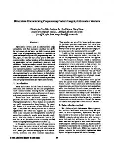
Figure 3: Outline of Purdue’s campus network topology.
Figure 4:
Number of buildings spanned by a VLAN.
Performance inefficiencies: While VLANs simplify management, they introduce inefficiencies. For example, in Figure 1, the shortest physical path between H1 and H2 is simply H1 − S1 − H2, as both hosts are attached to the same switch. However, the path that data flows between them is much longer as shown in the figure. Using substantially longer paths for data flows may involve longer delays, redundant transmission, and loops. Further, longer paths increase the likelihood of failures, and complicate performance and failure diagnosis. For example, in Figure 1, if H1 and H2 were in the same building in campus, and other devices were located in external buildings, communication could be disrupted by issues such as power failure in external buildings. Placement of designated router: While inefficiencies are inherent to VLANs, the extent of inefficiency is impacted by the placement of the designated router for the VLAN. For example, in Figure 1, the inefficiencies of communication between H1 and H2 would be minimized if R1 were chosen as the designated router of VLAN 2 instead of R2. An ideal placement strategy must consider the overall span of a VLAN, and must choose a designated router as close as possible to the majority of hosts in that VLAN. Other considerations include the traffic patterns of hosts, such as which servers that the hosts typically communicate with. Configuring allowed lists: Both ends of every trunk link need to be explicitly configured with a list of VLANs allowed on that link. In Figure 1, H1 and H3 belong to VLAN 1, and hence trunk links S-S1, and S-S2 must be configured to permit traffic from VLAN 1. Further, trunk link S − S2 should not permit traffic belonging to VLAN 2, since all hosts of VLAN 2 are clustered on the same side of the link. Constraining VLANs permitted on a trunk link is necessary to minimize propagation of broadcast traffic of those VLANs.
3.
OPERATIONAL NETWORK STUDY
Figure 3 depicts a conceptual outline of the Purdue campus topology. Typically, each building has a router with a link to the core. This router connects all hosts in that building to the rest of the campus network. Our key findings are: Prevalence of virtualization: Figure 4 considers buildings spanned by the hosts in a VLAN. While 50% of the VLANs span only one building, about 10% of the VLANs span more than 5 buildings, and the largest VLAN spans over 60 buildings. Example VLANs with large spans include those that contain hosts in all classrooms or in all conference rooms on campus. Typically, all of these VLANs are managed by the same administrative sub-unit distinct from the main campus operators, and use of VLANs simplifies the task of allocating IP address blocks to the sub-units. Performance inefficiencies: To characterize the performance inefficiencies, we use the routing inefficiency metric, defined as the ratio of the number of hops on the path that
VLAN Span Single Bldg 2 Bldgs Multi(> 2) Bldgs
4
6
8
10
12
14
16
Routing Inefficiency
Figure 5:
Inefficiency between hosts from different VLANs. Total VLANs 149 60 96
Suboptimal Placement 16 20 56
Table 1: Characteristic of designated router placement. data flows between two hosts to the number of hops on the shortest physical path between them. Figure 5 shows the CDF of routing inefficiencies for 3 buildings. For each building, the routing inefficiency is computed for representative hosts in each pair of distinct VLANs in that building. Each curve corresponds to one building. The X-Axis is the routing inefficiency, and the Y-Axis shows the fraction of VLAN pairs for which the inefficiency is less than a particular value. For all buildings, the inefficiency is significant, and greater than 4 for about 12% of the pairs. Placement of designated routers: We investigated whether the inefficiencies could have been minimized by more careful placement of designated routers. Table 1 considers whether the designated router for a VLAN was placed in the building with the most hosts in that VLAN. Overall, this was indeed the case with 89% of the single building VLANs, 67% of the 2-building VLANs, and 42% of multi-building VLANs. Among the 20 2-building VLANs that did not conform, 11 have their designated routers placed in the building with none or fewer than 10% of the hosts in the VLAN. Among the 56 multi-building VLANs that did not conform, there were 34 VLANs where the building with most hosts had 70% or more of all hosts in the VLAN. Further discussions with operators revealed that a common reason for sub-optimal placement of designated routers was changes to the network - as hosts were added to and removed from VLANs, previous choices of reasonable placement were no longer appropriate. Configuration of allowed VLANs: Potential misconfiguration of VLANs permitted on trunk links includes Missing VLANs, where a VLAN that should be specified in the allowed list of a trunk link is omitted, and Unnecessary VLANs where a VLAN is unnecessarily specified on a trunk link. We analyzed 131 configuration files corresponding to trunk links that connect the primary router of a building to the core. Of these, only 5 had errors corresponding to missing VLANs. Further, 8 VLANs were affected, and each error impacted (disconnected) 2.25 hosts on average. It is reasonable that these errors are small, since these would lead to complaints from hosts (users) that are disconnected from the network. However, when unnecessary VLANs are considered, 119 of 131 configurations contain such errors, with over 6000 cases of unnecessary VLAN specification. Details and Future Work: For more detailed analysis results, please refer to our Technical Report at ”http://www.ece.purdue.edu/∼isl/publications.htm”. Our future work includes analyzing more networks, using VLANs as a case-study for abstraction design, and studying implications of VLANs for performance and failure diagnosis.