is common in the industrial robotic programming, defining a free zone .... Delphi programming language. ..... cess to the chess robot system using the Internet.
CHESS ROBOT SYSTEM: A MULTI-DISCIPLINARY EXPERIENCE IN AUTOMATION Jos´ e Gon¸ calves, Jos´ e Lima, Paulo Leit˜ ao
Instituto Polit´ecnico de Bragan¸ca, Departamento de Electrotecnia, Quinta de Sta Apol´ onia 1134, 5301-857 Bragan¸ca, Portugal {goncalves,jllima,pleitao}@ipb.pt
Abstract: This paper describes a chess robot system that allows remote users to play chess, using a six axes anthropomorphic robot to move chess pieces in the chessboard on getting commands from the player and from the application chess engine. This experience allowed applying the concept of ’learning by doing’, involving the integration of multi-disciplinary skills and teams. Keywords: Robotics, Vision, Remote Control, Industrial Automation, Education
1. INTRODUCTION The automation laboratory of the Escola Superior de Tecnologia e Gest˜ao, from the Instituto Polit´ecnico de Bragan¸ca, possess a set of industrial automation systems and technologies, aiming the apprehension, learning and training of skills in the automation scientific domain, both included in research activities and in the curricula of Electrical Engineering, Mechanical Engineering, Computer Engineering and Industrial Engineering courses. One of the available automation systems in the laboratory is an industrial anthropomorphic robot ABB IRB 1400. Industrial robots allow executing repetitive operations normally performed by human operators. The word robot is derived from a satiric theater play, written by Karel Capek in 1921, who used it to designate labour force. The introduction of robots allows to increase the productivity (with no interruptions, absenteeism, etc.) and to increase the robustness, speed and resistence to hostile environments. Aiming to demonstrate the potentialities of the automation systems and technologies, namely robotics and artificial vision, it was initiated an
internal project to develop a chess robot system. This project allowed to run an experience in automation education applying the concept of ’learning by doing’, involving the integration of multi-disciplinary skills and teams. Similar initiatives are reported in the literature, such as Eric, a Chess playing Robot (Pires, 1999) developed at Department of Mechanical Engineering of University of Coimbra, and ChessRobot.net developed at Institute of Production Engineering of Tampere University of Technology (Lobov et al., 2004). The chess robot system described in this paper, and partially presented at the Robotics Portuguese Open 2004 - Scientific Meeting (Sousa et al., 2004), allows remote users to play chess (playing with the white chess pieces). The chess robot system uses the six axes anthropomorphic robot ABB IRB 1400, which holds an electro-pneumatic gripper with parallel fingers that pick and place chess pieces. The robot is able to move chess pieces in the chessboard on getting commands from the player and from the application chess engine.
The paper is organized as follows: initially, Section 2 describes the system architecture. Section 3 describes the main hardware components and Section 4 describes the software application, given details about all modules included in the application. Section 5 describes the validation mechanism giving special attention to the vision system. At the last, Section 6 rounds up the paper with conclusions and presents the future work.
Start the game
gets the move that the player want to perform
sends the move to the chess engine
invalid
2. SYSTEM ARCHITECTURE
valid
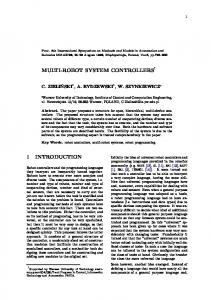
The chess robot system comprises the following main modules, as illustrated in the Figure 1: chessboard, robot, software application and artificial vision. Virtual Chessboard
correct move?
chess engine
asks the robot to execute the move in the real chessboard
the verification module asks the vision system if the target position is free
Player
chess logic control module
executes the move in the virtual chessboard
DB
target position is free?
robot interface (RobComm OCX )
not free
requests external help to remove piece
free sends a command to execute physically the the move
done?
yes
robot interface (RobComm OCX ) move executed by the robot?
verification module UDP
yes
real chessboard
game over?
yes game over
no
Fig. 1. Modules of the Chess Robot System The software application, which acts as the brain of the system, comprises the interface with the player, the chess logic control module, the chess engine, and the robot interface. The virtual chessboard gives an easy interface to the player, by displaying the chessboard of the chess game. On the virtual chessboard, the player drags and drops a white chess piece. The command associated to this movement is delivered to the chess logic control module that forwards it to the chess engine that evaluates the move and if the move is valid, the chess logic control module calculates the robot parameters for the move, as illustrated in the flowchart of the Figure 2. Then the chess logic control module sends movement commands to the robot, which reflects the move requested by the player, or the move calculated by the system after the invocation of the chess engine. The communication between the control module and the industrial robot is performed through the robot interface module.
white chess pieces
next play?
black chess pieces
asks the chess engine to define the next move of black chess pieces
Fig. 2. Chess Robot System Algorithm The integration of artificial vision in the chess robot system allows to implement a validation mechanism. Once the robot receives the move to perform, the validation mechanism verifies if the target position of the chess piece is free, asking the vision system. In affirmative case, the verification module gives authorization to the robot to move the chess piece, through the robot interface module.
3. HARDWARE ARCHITECTURE The physical movements of the chess pieces within the chessboard (and also the remotion of chess pieces from the chessboard) are executed by an anthropomorphic ABB IRB 1400 robot, as illustrated in the Figure 3. The robot is programmed using RAPID language, which allows to program
and control the robot in a simple and friendly way.
MoveL Offs(p30,regy2,-regx2,0),v100,fine,tool0; abre_garra; MoveL Offs(p30,regy2,-regx2,100),v5000,fine,tool0; repouso; ENDPROC
The robot program contains 6 registers that allows to control the execution of the physical movements: • regx1 - coordinate x of the origin position of the piece to move. • regy1 - coordinate y of the origin position of the piece to move. • regx2 - coordinate x of the target position of the piece to move. • regy2 - coordinate y of the target position of the piece to move. • reg11 - indication of a move request. • move - authorization to move a piece. The indication of a request to execute a physical move is given by the register reg11: if this register has the value 1 it means that a new request is arrived. If the robot is available, it begins the procedures to execute the move. Fig. 3. Robot Moving Chess Pieces The robot program, running in continuous and waiting for a command to execute a physical move, can be saw as a sequence of movements in the space passing through pre-defined positions along a trajectory with a specific orientation, velocity and acceleration. Initially, the robot is putted in a safe position and the gripper is opened, using respectively the functions repouso() and abregarra(). The functions to drag an drop pieces, follow a methodology that is common in the industrial robotic programming, defining a free zone where there are no limitations in the type of movements and the velocity used to perform those movements, and a conditioned zone, near the chessboard, where the movements must be linear and performed with conditioned velocity. The developed robot program is illustrated by showing the code for the agarra() function that allows the robot to pick a piece from one origin position and for the larga() function that allows the robot to place the piece in one destination position. PROC AGARRA() MoveJ Offs(p30,regy1,-regx1,100),vmax,fine,tool0; MoveL Offs(p30,regy1,-regx1,0),v100,fine,tool0; fecha_garra; MoveL Offs(p30,regy1,-regx1,100),vmax,fine,tool0; ENDPROC PROC LARGA() MoveJ Offs(p30,regy2,-regx2,100),vmax,fine,tool0;
Initially, and since all movements are made between the origin and the target positions, it should know the coordinates of those positions. The value of the coordinates for the two positions are defined in the regx1, regy1, regx2 and regy2 registers. In the robot program these positions are programmed using offsets in relation to one predefined point of the chessboard. The movement is only performed when the move register is equal to 1, which means that the verification module had verified if the target position is free, using the vision system, and gave authorization for the movement.
4. SOFTWARE APPLICATION The software application is responsible to build up the system, comprising mainly the virtual chessboard, the chess logic control module, the chess engine, the verification module and the robot interface. These components will be described in this section.
4.1 Virtual Chessboard The virtual chessboard is the graphical module that allows the user to communicate with the chess robot system. It reflects the state of the game using a graphical representation of the chessboard. Instead of using an existing graphical interface, for example the xboard (xboard, 2004) or the winboard (Winboard, 2004), respectively for Unix and
Microsoft platforms, the graphical interface was built from scratch, using the C++ programming language (Stroustrup, 2000). The option to build the graphical interface from scratch is sustained by the need to obtain full control over the system, allowing for example to wait that the robot finishes the movement of a chess piece. The graphical chessboard was developed using the Qt toolkit (Trolltech, 2003), that allows developing graphical interfaces in a friendly way.
4.2 Chess Logic Control Module The chess logic control module manages the flow of information/requests between the virtual chessboard, the chess engine and the robot interface. The communication of this module and the virtual chessboard and with the chess engine is implemented using pipes (a point-to-point communication mechanism). The communication with the robot interface is performed using Microsoft Foundation Classes (MFC).
4.3 Chess Engine In this work it was made the option to integrate an available chess engine instead of developing one from the scratch, since the core of this work is focused in the robotic and validation systems. The chosen chess engine was GnuChess (Gnuchess, 2004), which is an executable program in text mode. This chess engine, available of public domain (General Public License, 2004), runs as a separated process, communicating with the chess logic control module using anonymous pipes (Johnson and Troan, 1998). The chess engine starts two pipes, one for the standard input and another for the standard output. The chess engine reads commands from the standard input and writes the answers in the standard output. The state of the game and other parameters are controlled using commands that follow the xboard protocol (Chess Engine Communication Protocol, 2004), often used in chess engines. The protocol works in asynchronous mode, i.e. the entity that sends the message continues its activity without being blocked waiting for one answer. In this work the most used command is the order to move a chess piece using the coordinates in algebraic notation. For example, the coordinate a2a3 is a command to move from the position a2 to the position a3. If the move is valid the chess engine answers with the coordinates of the movement of a black chess piece, for example with d7d5.
The following example illustrates the direct access and usage of the GnuChess chess engine: # gnuchess.exe -x Chess Adjusting HashSize to 1024 slots a2a3 1. a2a3 1. ... d7d5 My move is: d7d5 In case that the movement request is invalid, the chess engine doesn’t return the coordinate of the next movement but the indication that the move is invalid because it violates the game rules. 4.4 Verification Module The main function of the verification module is to authorize the robot to execute physically a piece move, after to analyze if the target position of the piece is free. The verification module is cyclically reading the reg11 parameter to know if there is a request to move a chess piece. In affirmative case, it asks the vision system about the state of the target position. If the target position is empty, then it gives authorization to the robot to move the chess piece by writing the value 1 in the move register. The verification module as developed using the Delphi programming language. The communication between the verification module and the vision system is done through Ethernet using the UDP (User Datagram Protocol) protocol, which allows to distribute the image acquisition and the processing mechanism from the other components of the chess robot system. 4.5 Robot Interface The communication between the computational application and the industrial robot is essentially used when: • the computational application wants to give to the robot the command to execute a chess piece move; • the computational application needs to give to the robot the indication about the coordinates of the origin and target positions; • the verification module wants to give to the robot the authorization to start the movement. • the computational application wants to know the robot status. The robot interface is built upon the RobComm ActiveX provided by ABB (ABB, 1996). This interface uses essentially the following primitives to access the robot controller:
• The primitive S4ProgramNumVarWrite, that allows to write to a register of the robot program. • The primitive S4ProgramNumVarRead, that allows to read a register of the robot program. As an example, the request to move, in the real chessboard, a chess piece from one position to another, requires to use the S4ProgramNumVarWrite to update the regx1, regy1, regx2, regy2 and reg11 parameters. The x e y coordinate values are calculated making the direct conversion of an algebraic coordinate to integer values and then multiplying them for a scale factor. This scale factor corresponds to the size of each square of the real chessboard.
5. VISION SYSTEM The detection of chess pieces inside the chessboard can be done using several approaches, such as electrical capacitance, switches, or artificial vision. The last one is easier to setup not only due to the simplicity of hardware but also because it allows to build a robust system. Otherwise, it would be necessary to use 64 sensors as well as a complex electric circuit, drawing on to failures. In this work, the mechanism to detect pieces in the chessboard is based in artificial vision (see the screenshot of Figure 4). The developed system comprises an USB web-cam placed above the chessboard. The developed vision software implements a positioning calibration allowing to have a high degree of system flexibility in terms of size and positioning of the chessboard, as well as its distance to the camera. The calibration of colours is also possible in order to change the chessboard colours or pieces colours without interference.
tem, namely the method of noise filtering supported by a Gaussian filter, and the positioning and colour calibrations.
5.1 Noise Filtering During the image acquisition, some random noise is introduced by the acquisition system into the real image. In order to filter it, a Gaussian filter (Pratt, 1991) is implemented using a 2D convolution. Basically, the convolution is a window H that is scanned across the original image a. The output pixel value is the weighted sum of the input pixels within the window, where the weights are the values of the filter assigned to each pixel of the window itself. The window H with its weights is called the convolution kernel. If the filter H[i, j] is zero outside the rectangular window (i=0,1,...,I-1; j=0,1,...,J-1), the convolution can be written as the following finite sum: Y (m, n) = a(m, n) ⊗ H(m, n) = =
I−1 J−1 � �
H(i, j) · a(m − i, n − j)
i=0 j=0
where Y is the resulting image and H is the convolution kernel, given by: ⎛ ⎞ 1 1 1 H = ⎝1 1 1⎠ 1 1 1 Another form of noise is ”salt and pepper”. Here, the noise is caused by error in the transmission. The corrupted pixels are either set to the maximum value (which looks like snow) or to the minimum value (which looks like black points). A way to withdraw this noise is to use a median filter. In this application, it was not necessary to use the median filter since there was no ”salt and pepper” noise.
5.2 Chessboard Direction and Orientation
Fig. 4. Screenshot of the Vision System In the next sections will be described the details related to the implementation of the vision sys-
The chessboard positioning must be calibrated by the vision system in order to recognize exactly the 64 squares included in the chessboard. This positioning calibration could be dynamically found out across an extra image processing but, since the chessboard and the camera are motionless, this must be done just once. So, the chessboard corners must be introduced by the user clicking in the corners image. The knowledge of corners enables the system to calculate all square positions. This is true only if the barrel distortion lens is despised and if the camera is placed paralleled
to the chessboard (Pratt, 1991). If not, an image of the world map function must be created. The angle of the chessboard, see Figure 5, is needed for the calculation of the square coordinates.
x
C'
y
D
C
D'
B' B A'
A
Fig. 7. Square Rotation allows to find the edge coordinates for each square. (0,0)
Fig. 5. Chess Table Before the Rotation
m
x
n
A way to solve this problem is to rotate the all image in order to have the chessboard boarders in parallel to the image limits (i.e. β = 0o ), as shown in Figure 6. Another solution is keeping the original image and the square positions affected by this angle. y
Fig. 8. Chess Board Axes Considering the Figure 8 that shows all the 64 squares of the chessboard, and that m, n ∈ [0..8], the square coordinates are given by the following equations:
Fig. 6. Chess Table After the β Rotation For the described chess robot system application the first solution is better than the second one. On the one hand, it is easier to implement and more suitable for the user to understand it. On the other hand, it is slower than the second one and not appropriate for real-time applications.
Px (m) = Dx +
m × (Cx − Dx ) 8
Py (n) = Dy +
n × (Ay − Dy ) 8
where Px (m) is the X coordinate for the mth square and Py (n) is the Y coordinate for the nth square. As result, all square positions are circumscribed by yellow lines as illustrated in Figure 9.
The rotation referred above, through the β angle, is applied to the (A� x, A� y) point, resulting in the (Ax, Ay) point, as illustrated in the Figure 7, applying the image rotation theory, (Pratt, 1991) described by the following equation. � � �� � � � � cos(β) − sin(β) X1 − Ax Ax X2 = + Y2 Y1 − Ay Ay sin(β) cos(β) where the (X2 ,Y2 ) values are the new coordinates for the (X1 ,Y1 ) point. The knowledge of A, B, C and D coordinates (the four corners of the chessboard after the rotation)
Fig. 9. Square Positions
5.3 Colours Calibration An essential component of a coloured vision system is the colour classification and detection algorithms for each pixel. Considering the 16777216 colours (256∗256∗256) that is possible to represent with 8 bit for each component R, G and B, it is possible to build a coloured cube defined from (0, 0, 0) to (28 R; 28 G; 28 B) with RGB components in each vertex, as shown in the Figure 10.
If the lightning changes frequently, an auto-iris lens could be used (assuming that light wave length is constant).
5.4 Decision System The main objective of the vision system is to detect if any chess piece is inside of a requested square. This can be done applying the probabilities theory. The available information to take the decision is: (1) The colour arrangement (left upper square colour introduced by user). (2) The square positions. (3) The number of guessed pixels for each chess colour for each square. The square areas are scanned and for each one it must be studied the colour of each pixel. A gap of 15%, as shown in the Figure 11, is not considered in order to avoid errors.
;;; ;; x
y
Fig. 10. RGB Cube Some main colour vectors are presented in the following table: RGB coordinates (255,0,0) (0,255,0) (0,0,255) (0,255,255) (255,0,255) (255,555,0) (255,255,255)
Point R G B C M Y W
Colour Red Green Blue Cyan Magenta Yellow white
A cube edge represents 256 discrete and different colour points and there are 16777216 different coloured points inside the cube. It is necessary to teach the system of the 2 visible colours in chessboard that will be known as chessboard colours. In practice, several cube points are fitted in one chessboard colour. In short, calibration fits chessboard colours and cube points (RGB combinations). By this way, it is now possible to guess the colour for each square as well as its probability. It is necessary to calibrate the chess colours in the setup of each game and after a lightning change. This calibration can be saved in a file that keeps all RGB combinations for each colour. Lightning stability and camera control are very important to this task (image processing). Lens iris must be stilled; otherwise colours calibration is lost. When the robot arm moves in front of the camera, the images should not be observed and the lens iris should be stilled too.
yf-yi
xf-xi
Fig. 11. Square Areas Scan
In this case, δ = 0.15 × (xf − xi ) and θ = 0, 15 × (yf −yi ). Due to the camera resolution parameters (different image width and height), the δ and θ values are usually different. The probability to have chess piece inside a square can be found considering the square area and the number of pixels guessed of the same colour as the chess colour arrangement. Despising the error introduced by the acquisition system, the following expression shows the probability of piece existence. ColouredM atchedP oints p(existingpiece) = 1 − area where: area = (xf − xi ) · (yf − yi ) As illustrated in the Figure 11, the decision about the piece existence can be guessed through a threshold probability value pre-defined by the user. Low values of this threshold (like 0.1 up to 0, 4) are common because the number of affected pixels when the piece exists is really lower than area.
6. CONCLUSIONS AND FUTURE WORK In this paper it was described the implementation of a playful application that allows to demonstrate the capabilities associated to robotic systems, but also the application of the concept of ’learning by doing’, involving the integration of multi-disciplinary skills and teams. The objective was to built a chess robot system that allows remote users to play chess, using a six axes anthropomorphic robot, available at the automation laboratory of the Polytechnic Institute of Bragan¸ca, to move chess pieces in the chessboard on getting commands from the player and from the application chess engine. An important issue associated to the chess robot system is the vision system that allows to implement a validation mechanism, avoiding that the robot moves one chess piece to a position not empty. Some problems and the implemented solutions occurred during the implementation of the vision systems were point out. As future work, we intent to allow the remote access to the chess robot system using the Internet.
REFERENCES ABB (1996). RobComm User´s Guide. ABB Flexible Automation inc. Chess Engine Communication Protocol (2004). http://www.timmann.org/xboard/engine-intf.html. Gamma, Erich, Richard Helm, Ralph Johnson and John Vlissides (1994). Design Patterns. Addison-Wesley. General Public License (2004). http://www.gnu.org/copyleft/gpl.html. Gnuchess (2004). http://www.gnu.org/software/chess/chess.html. Johnson, Michael K. and Erik W. Troan (1998). Linux Application Development. AddisonWesley. Lobov, A., E. Lopez, J. Lastra and R. Tuokko (2004). ChessRobot.net: An Interactive Online Experience. In: Proceedings of the 2nd International Conference on Industrial Informatics. Berlin, Germany. pp. 64–68. Pires, N. (1999). Eric, a Chess Playing Robot. http://robotics.dem.uc.pt/norberto/eric/. Pratt, William K. (1991). Digital image processing. John Willey and Sons Inc. Sousa, F., J. Gon¸calves and P. Leit˜ ao (2004). Sistema Robotizado de Xadrez. In: Proceedings of the Scientific Meeting of Rob´ otica 2004. Porto, Portugal. pp. 163–168. Stroustrup, B. (2000). The C++ Programming Language. Addison-Wesley. Trolltech (2003). Qt trolltech toolkit. http://www.trolltech.com.
Winboard (2004). http://www.tim-mann.org/xboard.html. xboard (2004). http://www.tim-mann.org/xboard.html.