Hindawi Publishing Corporation International Journal of Distributed Sensor Networks Volume 2015, Article ID 572861, 11 pages http://dx.doi.org/10.1155/2015/572861
Research Article Chirp Spread Spectrum Transceiver Design and Implementation for Real Time Locating System Sangdeok Kim and Jong-Wha Chong Department of Electronics and Computer Engineering, Hanyang University, No. 702, R&D Building, 222 Wangsimni-ro, Seongdong-gu, Seoul 133-791, Republic of Korea Correspondence should be addressed to Jong-Wha Chong;
[email protected] Received 25 December 2014; Accepted 6 April 2015 Academic Editor: Jie Wang Copyright © 2015 S. Kim and J.-W. Chong. This is an open access article distributed under the Creative Commons Attribution License, which permits unrestricted use, distribution, and reproduction in any medium, provided the original work is properly cited. A chirp spread spectrum (CSS) transceiver architecture for IEEE 802.15.4a is proposed and implemented. In the transmitter, the size of the read-only memory that stores CSS signal samples for the chirp modulator is reduced by removing duplicate samples among subchirps. In the receiver, a matched filter is utilized to remove the other band noise caused by the band hopping property of CSS. A robust time synchronizer and chirp demodulator based on the matched filter are proposed. Low complexity architectures of the matched filter and biorthogonal decoder are also proposed. All of the proposed architectures are implemented in the fieldprogrammable gate array chip and verified.
1. Introduction The IEEE 802.15.4a committee adopted chirp spread spectrum (CSS) based on the industrial, scientific, and medical band for a new standard whose objectives are to provide low data rate communications, a high-precision ranging/location capability, low power, and low cost, as in [1]. CSS utilizes chirp signals categorized as spread spectrum signals and can achieve high-precision ranging results because of the superior correlation property of the chirp signals. Recently, the demand for localization systems has grown tremendously. Localization management and mobile management have become significant issues in providing a seamless and ubiquitous environment for mobile users. As a result, many studies have been conducted for the development of localization algorithms and systems using CSS as in [2–9]. In contrast, there are few studies on the transceiver architecture of CSS. Jeong et al. [10] proposed the rake receiver for CSS, and Kim et al. [11] introduced the autocorrelation-based receiver and a receiver that adopts the dual-band filtering method. Yaqoob and Chong [2] proposed a decision feedback receiver that can be applied to CSS. For fast development of the localization system based on CSS, the modulation and demodulation technique of CSS should be developed first. In this paper, a novel transceiver
architecture of CSS is proposed and implemented. In the transmitter, the low-complexity architecture of the chirp modulator is proposed. The size of the read-only memory (ROM) is reduced based on the relationships among CSS subchirps. In the receiver, matched filter-based architecture is proposed in order to remove the other band noise caused by the band hopping property of CSS. A robust time synchronizer and chirp modulator based on the matched filter are presented. Low-complexity architectures of the matched filter and the biorthogonal decoder are also proposed. The proposed architectures are designed and verified in the fieldprogrammable gate array (FPGA) chip. This paper is organized as follows. Section 2 describes the signal model and the properties of CSS. The proposed transmitter and receiver architectures are proposed in Sections 3 and 4, respectively. Simulation results are shown in Section 5 and an implementation summary and test results are described in Section 6. Finally, we conclude this paper in Section 7.
2. Signal Model and Properties of CSS In this section, the signal model and the properties of CSS that are motivation for the proposed architecture are
International Journal of Distributed Sensor Networks
0
0.5
1
1.5
2
2.5 Time
3
The 3rd subchirp
The 1st subchirp
The 0th subchirp Amplitude
1 0.5 0 −0.5 −1
The 2nd subchirp
Time
Frequency
2
3.5
4
4.5 ×10⁻⁶
Low band spectrum
High band spectrum
Additive white Gaussian noise A
−1.5
−1
B
C
−0.5 0 0.5 Frequency (MHz)
1
1.5
2 ×10⁷
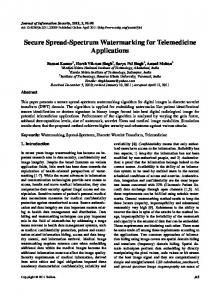
Figure 2: CSS spectrum.
Real Imaginary
Figure 1: Time-frequency and time domain waveforms of the four subchirps in SOP 1.
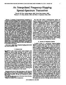
described. For convenience, we explain the signal model and the properties of CSS based on a simultaneously operating piconet (SOP) 1 in [1]. 2.1. Signal Model. The frequency band of CSS can be divided into two subbands: high and low bands. In each band, there are two subchirps, which have different directions of sweeping frequency as described in Figure 1. Four subchirps compose a symbol of CSS. As in [1], the digitized four subchirps of CSS at the baseband are presented by 𝜇 𝑠𝑘,𝑛 = exp [𝑗 (𝜔𝑘 𝑛 + 𝜉𝑘 ( ) 𝑛2 )] ⋅ 𝑃𝑛 , 2
0 −5 −10 −15 −20 −25 −30 −35 −40 −45 −50 −55 −2
(1)
where 𝑘 denotes the subchirp index (𝑘 = 0, 1, 2, and 3) and 𝑛 denotes the sample index where |𝑛| ≤ (1/2) ⌊𝑇sub /𝑇𝑠 ⌋. ⌊𝑥⌋ is the largest integer that is less than or equal to 𝑥. 𝑠𝑘,𝑛 denotes the 𝑛th sample of the 𝑘th subchirp, 𝑇sub denotes the time duration of a subchirp, 𝑇𝑠 is the sampling duration, 𝑗 = √−1, 𝜔𝑘 denotes the center frequency of the 𝑘th subchirp, and 𝜉𝑘 is a numerical parameter for subchirp directions where 𝜉0 and 𝜉1 are 1 and 𝜉2 and 𝜉3 are −1 in SOP 1. The constant 𝜇 denotes the characteristics of the subchirp and 𝑃𝑛 is a raised cosine window which is equal to zero outside of the subchirp. 2.2. Band Hopping Property of CSS. As shown in Figure 1, the frequency band of CSS is divided into two subbands: high and low bands. The 0th and 3rd subchirps are in the low band whereas the 1st and 2nd subchirps are in the high band. Namely, the subchirps in CSS are transmitted by hopping different bands. Due to the band hopping property, CSS has two different spectrums which alternately appear in the time domain, as in Figure 2. The received signals are filtered by an analog filter that covers the two subbands in the analog part such as the radio
frequency (RF) circuit. In the digital part, if the matched filter is not used for receiving the low band signal, the white noise corresponding to areas A, B, and C in Figure 2 degrades the demodulation performance. Then, the signal-to-noise ratio (SNR) is decreased by the other band white noise in area C in Figure 2 which would be removed. This means that the matched filter must be adopted in CSS to obtain the maximum SNR for demodulation. Therefore, the matched filter is utilized for demodulation in this paper. A time and frequency synchronizer based on the matched filter is also proposed. 2.3. Relationships among Subchirps. The relationships among subchirps are investigated. We examine the relationship between the 0th and 1st subchirps in SOP 1. The raised cosine window, 𝑃𝑛 , is bisymmetric, and 𝜔1 is replaced by −𝜔0 because 𝜔1 has a different sign but the same value as 𝜔0 , as in [1]. Then, the 1st subchirp is expressed by the reverse indexed 0th subchirp as in 𝜇 𝑠1,𝑛 = exp [𝑗 {𝜔1 𝑛 + ( ) 𝑛2 }] ⋅ 𝑃𝑛 2 𝜇 = exp [𝑗 {𝜔0 (−𝑛) + ( ) (−𝑛)2 }] ⋅ 𝑃−𝑛 = 𝑠0,−𝑛 . 2
(2)
Using a similar process, the 2nd and 3rd subchirps are expressed by the conjugate 0th subchirp in (3) and the conjugate and reverse indexed 0th subchirp in (4), respectively. Consider 𝜇 𝑠2,𝑛 = exp [𝑗 {𝜔2 𝑛 − ( ) 𝑛2 }] ⋅ 𝑃𝑛 2 (3) 𝜇 2 ∗ = exp [−𝑗 {𝜔0 𝑛 + ( ) 𝑛 }] ⋅ 𝑃𝑛 = 𝑠0,𝑛 , 2 𝜇 2 𝑠3,𝑛 = exp [𝑗 {𝜔3 𝑛 − ( ) 𝑛 }] ⋅ 𝑃𝑛 2 (4) 𝜇 ∗ = exp [−𝑗 {𝜔0 (−𝑛) + ( ) (−𝑛)2 }] ⋅ 𝑃−𝑛 = 𝑠0,−𝑛 . 2 The hardware complexity of the chirp modulator and the matched filter in the transceiver is reduced by using these
International Journal of Distributed Sensor Networks relationships among subchirps. The proposed architectures are described in Sections 3 and 4 in detail.
3. Architecture of the CSS Transmitter The CSS transmitter is composed of three essential blocks: the biorthogonal coder, differential phase shift keying (DQPSK) mapper, and chirp modulator. Biorthogonal codes are utilized to better withstand the effects of various channel impairments, such as noise, fading, and interference. Three bits are mapped to a four-chip biorthogonal codeword (𝑑0 , 𝑑1 , 𝑑2 , 𝑑3 ) in the 1 Mbps mode, as in [1]. Each pair of in-phase and quadrature (𝐼 and 𝑄) chips of codewords is mapped to a QPSK symbol for subchirps. For example, 𝑐0 of the 𝐼 and 𝑄 chips is mapped to a QPSK symbol for the 0th subchirp. The QPSK symbols are differentially encoded. Then, the DQPSK symbols are modulated by multiplication between the DQPSK symbols and the reference samples of the subchirps. In this paper, the size of the ROM for the reference subchirp in the chirp modulator is reduced by using the relationships among subchirps mentioned in the previous section. Since the samples of the 1st, 2nd, and 3rd subchirps are generated by the reverse indexed and/or conjugate samples of the 0th subchirp as in Section 2, the samples of the reference subchirp for the chirp modulator are composed of only the samples of the 0th subchirp in the proposed transmitter; as a result, the ROM size is reduced by the amount of 75%. Figure 3 explains the generation of the four subchirp samples in SOP 1. By only using the samples of the 0th subchirp stored in the ROM, the 1st, 2nd, and 3rd subchirp samples are generated by changing the reading address and sign. In Figure 3, 𝑁sub means the number of samples per subchirp. Figure 4 shows the transmitter architecture of CSS. DEMUX denotes the demultiplexer, S/P means serial-toparallel converter, P/S means parallel-to-serial converter, and 𝑧−4 denotes the delay of four cycles. The complex multiplier in Figure 4 can be replaced by an adder/subtractor since the DQPSK symbol has four phases, 1 + 𝑗, 1 − 𝑗, −1 + 𝑗, and −1 − 𝑗, as in [1]. For example, if the reference subchirp sample is 𝑎 + 𝑏𝑗 and the DQPSK symbol is 1 − 𝑗, the output sample is (𝑎 + 𝑏) + (𝑏 − 𝑎)𝑗. Then, the complex multiplier is replaced by one adder and subtractor.
3 subchirps in Section 2, the duplicate coefficients of the filter are removed. The coefficients of the filter are composed of only the 0th subchirp samples. In [12–14], the matched filter is generally implemented using a transposed form since the multiplication of the filter can be substituted by addition and shift. The proposed matched filter also adopts the transposed form. A symbol of CSS is composed of the four subchirps. Therefore, four subfilters are required for CSS. Since the four subfilters are complex filters, the 𝐼 and 𝑄 channels should be considered separately. The 𝐼 and 𝑄 outputs of the 0th subfilter are expressed by 𝐼 = 𝑚0,𝑛
𝑄 𝑚0,𝑛
=
4.1. Matched Filter for the Chirp Demodulator. Due to the band hopping property of CSS, as described in Section 2, the matched filter should be adopted in the chirp demodulator to remove the other band noise. Since low-complexity implementation is very important for CSS, we propose a new architecture for the matched filter. Using the relations among
∑
𝑙=−(1/2)𝑁sub (1/2)𝑁sub
∑
𝑙=−(1/2)𝑁sub
𝐼 𝐼 𝑦𝑛+𝑙 𝑠0,𝑙 −
𝐼 𝑄 𝑦𝑛+𝑙 𝑠0,𝑙
+
(1/2)𝑁sub
∑
𝑙=−(1/2)𝑁sub (1/2)𝑁sub
∑
𝑙=−(1/2)𝑁sub
𝑄 𝑄 𝑦𝑛+𝑙 𝑠0,𝑙 ,
(5) 𝑄 𝐼 𝑦𝑛+𝑙 𝑠0,𝑙 ,
where { }𝐼 and { }𝑄 denote the 𝐼 and 𝑄 components of { }, 𝐼 is the 𝑛th 𝐼 output of the 0th subfilter, respectively, 𝑚0,𝑛 𝐼 𝐼 is the 𝑦𝑛 is the 𝑛th received sample of the 𝐼 channel, 𝑠0,𝑛 𝑛th 𝐼 coefficient that is matched to the 𝑛th 𝐼 sample of the 0th subchirp, and 𝑁sub is the number of coefficients in the subfilter. The coefficients of the 1st, 2nd, and 3rd subfilters are replaced by those of the 0th subfilter by using the relations among the subchirps described in Section 2. As a result, the four subfilters are designed by utilizing only the coefficients that are matched to the 0th subchirp. The output sequences of the 1st, 2nd, and 3rd subfilter are presented in the following: 𝐼 = 𝑚1,𝑛
𝑄 𝑚1,𝑛 =
𝐼 𝑚2,𝑛 =
𝑄 𝑚2,𝑛 =
4. Architecture of the CSS Receiver The CSS receiver is divided into six blocks: the chirp demodulator, DQPSK symbol demapper, biorthogonal decoder, time synchronizer, frequency synchronizer, and automatic gain control (AGC).
(1/2)𝑁sub
𝐼 𝑚3,𝑛 =
𝑄 𝑚3,𝑛 =
(1/2)𝑁sub
∑
𝑙=−(1/2)𝑁sub (1/2)𝑁sub
∑
𝑙=−(1/2)𝑁sub (1/2)𝑁sub
∑
𝑙=−(1/2)𝑁sub (1/2)𝑁sub
∑
𝑙=−(1/2)𝑁sub (1/2)𝑁sub
∑
𝑙=−(1/2)𝑁sub (1/2)𝑁sub
∑
𝑙=−(1/2)𝑁sub
𝐼 𝐼 𝑦𝑛+𝑙 𝑠0,−𝑙 −
𝐼 𝑄 𝑦𝑛+𝑙 𝑠0,−𝑙 +
𝐼 𝐼 𝑦𝑛+𝑙 𝑠0,𝑙 +
𝐼 𝑄 𝑦𝑛+𝑙 𝑠0,𝑙 −
(1/2)𝑁sub
∑
𝑙=−(1/2)𝑁sub (1/2)𝑁sub
∑
𝑙=−(1/2)𝑁sub (1/2)𝑁sub
∑
𝑙=−(1/2)𝑁sub (1/2)𝑁sub
∑
𝑙=−(1/2)𝑁sub
𝐼 𝐼 𝑦𝑛+𝑙 𝑠0,−𝑙 +
𝐼 𝑄 𝑦𝑛+𝑙 𝑠0,−𝑙 −
𝑄 𝑄 𝑦𝑛+𝑙 𝑠0,−𝑙 ,
𝑄 𝐼 𝑦𝑛+𝑙 𝑠0,−𝑙 ,
𝑄 𝑄 𝑦𝑛+𝑙 𝑠0,𝑙 ,
𝑄 𝐼 𝑦𝑛+𝑙 𝑠0,𝑙 ,
(1/2)𝑁sub
∑
𝑙=−(1/2)𝑁sub (1/2)𝑁sub
∑
𝑙=−(1/2)𝑁sub
𝑄 𝑄 𝑦𝑛+𝑘 𝑠0,−𝑙 ,
𝑄 𝐼 𝑦𝑛+𝑙 𝑠0,−𝑙 .
(6) The proposed matched filter is based on a transposed form, which is composed of two parts: a multiplier block (MB) and a register and adder block (RAB). In the transposed
4
International Journal of Distributed Sensor Networks ROM: I samples of the 0th subchirp
··· 0 1 2 3
Nsub − 1
···
Read I samples of the 0th subchirp Read I samples of the 1st subchirp Read I samples of the 2nd subchirp Read I samples of the 3rd subchirp (a) Generation of 𝐼 samples
ROM: Q samples of the 0th subchirp 0 1 2 3
··· ···
Nsub − 1
Read Q samples of the 0th subchirp Read Q samples of the 1st subchirp Read Inverter
+
Q samples of the 2nd subchirp
1
Read Inverter
+
Q samples of the 3rd subchirp
(b) Generation of 𝑄 samples
Figure 3: Generation of the four subchirp samples by only using the 0th subchirp samples.
form, the hardware complexity of the MB is reduced as in [12– 14] because all multiplications are products of a single input multiplicand. Figure 5 shows the proposed architecture of the matched filter for CSS. The MBs, which are composed of the coefficients matched to the 0th subchirp, are shared by the four subfilters. For 𝐼 and 𝑄 input sequences, there are two MBs
that are composed of adders and a shifter as in [12]. The 0th and 2nd subfilters share RABs because of the conjugate relationship between the 0th and 2nd subchirps; eventually, the outputs of the 0th and 2nd subfilters are determined by the adders or subtractors that add or subtract the outputs of shared RABs. The 1st and 3rd subfilters also have the same relationships described above. In the 1st and 3rd subfilters,
International Journal of Distributed Sensor Networks
5
Biorthogonal mapper
P/S
DEMUX
QPSK mapper
S/P
S/P
×
P/S ··· 01
7
Code table
×
Read ··· 0123
ROM: CSS signal samples N−1
- Complex multiplier: ×
RAB RAB RAB
+
RAB
MB (S0i ) (S0r )
+
+
RAB
Reverse
RAB
+
Reverse
RAB RAB
Reverse .. . Reverse: . ..
+
Reverse
4.3. Biorthogonal Decoder. Four chips that are generated from QPSK demapping of the four subchirps compose a biorthogonal codeword. The 𝐼 and 𝑄 codewords are independently demapped according to a biorthogonal code table. To find the codeword that has the maximum probability, a code correlator is utilized. The codeword that has the maximum correlation value is selected. In this paper, a low-complexity biorthogonal decoder is proposed. The code correlator is designed only using an adder/subtractor. The correlation results of the 0th codeword and the 4th codeword have the same absolute value but different signs because of the antipodal relation between the 0th and 4th codewords. Furthermore, the 1st and 5th, the 2nd and 6th, and the 3rd and 7th codewords have antipodal relations; thus, only four code correlators are used and the largest absolute value of the correlation results is found. Then, a final codeword is selected according to the sign of the correlation result. Figure 6 shows the proposed biorthogonal decoder. The code correlator is designed using eight adders/subtractors. The correlation result that has the maximum absolute value is selected. Then, according to the sign of the correlation result, a final codeword is selected. After the biorthogonal demapping, the selected codeword is parsed.
xni
+
+
+
+
MB
4.2. DQPSK Decoder and QPSK Demapper. After chirp demodulation, the DQPSK symbol is differentially decoded by using differential multiplication. The QPSK symbol demapping is then performed by multiplying 1 + 𝑗. For reducing hardware complexity, the complex multiplier is converted into an adder and subtractor as described in Section 3.
xnr
(S0i )
the reverse blocks change the order of input sequences in order to generate the reverse indexed coefficients. The RABs accumulate the output sequences of reverse blocks.
(S0r )
Figure 4: CSS transmitter architecture.
+
+
RAB: .. . . ..
+
+
+
+
+
−
+ −
+
−
+ −
+
I m0,n
Q m0,n
Q m2,n
The 0th subfilter
The 2nd subfilter
I m2,n
I m1,n
The 1st subfilter
Q m1,n
Q m3,n
The 3rd subfilter
I m3,n
z−1 +
.. .. z−1 . . . .. +
Scalar: Vector:
Figure 5: The proposed architecture of the matched filter.
6
International Journal of Distributed Sensor Networks The code correlator +
+
[1 1 1 1]
ABS
+
The 1st chip
−
−
+
[1-1 1-1]
−
[1 1-1-1]
+
The 2nd chip
+
−
+
The 3rd chip
−
+
−
−
ABS
ABS
[1-1-1 1] −
Biorthogonal code table 000 001 010 011 100 101 110 111
Find maximum value and select the codeset using the sign
The 0th chip
ABS
Save signs
Figure 6: The proposed biorthogonal decoder.
Frequency synchronizer (see [21])
DAC
ADC
()∗
×
Dsub Dsub Dsub
Dsym
()∗
×
Dsub Dsub
1+j ×
Dsub
1+j ×
Dsym
()∗
×
Dsym
()∗
×
×
1+j ×
Data parser
VGA
Dsym
Biorthogonal decoder (see Figure 7)
Received signal
Matched filter (see Figure 6)
Frame detector
Decoded data
+ ABS Dsym
+
ABS Dsub∗ 4
×
z−1
Comparator
1+j
Packet detection (control signal)
AGC module (see [24])
Figure 7: The proposed receiver architecture for CSS.
4.4. Time Synchronizer. In CSS, time synchronization is composed of packet detection and frame detection. The packet detection is performed in the preamble and, following this, the frame detection is performed in the start frame delimiter as in [1]. In packet detection, whether a packet exists
or not is decided whereas, in frame detection, an accurate start point of the data in a packet is searched for. As in [15–17], an autocorrelation-based packet detector is generally used because of its immunity to the channel effect. The packet detector, however, has a problem with the timing
International Journal of Distributed Sensor Networks
7
100
1 0.8 Decision variable
10−1
BER
10−2 10−3
0.6 The Cox algorithm, SNR = −0.9 dB
0.4 0.2
10−4
0
10−5
−0.2 −15 0
−5
5
10
Figure 8: Comparison of BER performances.
𝑙=−(1/2)𝑁sub
∗ 𝑦𝑛+𝑙 𝑠𝑘,𝑙 ,
(7)
=
∑
𝑙=−(1/2)𝑁sub
∗ 𝑦𝑛+𝑙 𝑠𝑘,𝑙
(
(1/2)𝑁sub
∑
𝑙=−(1/2)𝑁sub
10
15
∗ ∗ 𝑦𝑛+𝑙−𝑁sym 𝑠𝑘,𝑙 )
,
0.8
0.6
0.4
0.2
(8)
where 𝑠𝑘,𝑛 denotes coefficients of the 𝑘th matched filter, 𝑁sub is the number of samples per subchirp, and ∗ is the complex conjugation. The cross-correlation results of the subchirps are accumulated by
−100
−50
0 50 Time (sample)
100
(9)
𝑘=0
Using 𝑎𝑛 without normalizing will yield a different performance in different noise environments as in [21]. To resolve this problem, 𝑎𝑛 should be normalized by using 𝑏𝑛 as given
150
Proposed Cox
Figure 10: Timing metrics of the proposed and Cox’s detector.
in (10), and the decision variable, 𝑐𝑛 , as in (11), which uses 𝑎𝑛 and 𝑏𝑛 is proposed in this section. Consider
3
𝑎𝑛 = ∑ 𝑑𝑘,𝑛+(3−𝑘)𝑁sub .
20
1
0 −150
∗ 𝑑𝑘,𝑛 = 𝑚𝑘,𝑛 𝑚𝑘,𝑛−𝑁 sym (1/2)𝑁sub
0 5 SNR (dB)
Figure 9: Decision variables of the proposed algorithm and Cox’s algorithm.
Timing metric
metric plateau. Some researchers developed algorithms to resolve the timing metric plateau by altering the normalization method in [18–20]. In this section, we propose a new packet detector using a cross-correlation in order to remove the other band noise caused by the band hopping property of CSS. The timing metric plateau problem is also resolved since the cross-correlation results of subchirps have sharp peaks. The channel effect is suppressed by using the autocorrelation followed by cross-correlation. The cross-correlation results are mathematically expressed in (7). Then, we perform the autocorrelation as in (8). Consider ∑
−5
E[·], signal, proposed E[·], signal, Cox 3 ∗ Var[·], signal, proposed 3 ∗ Var[·], signal, Cox E[·], noise, proposed E[·], noise, Cox 3 ∗ Var[·], noise, proposed 3 ∗ Var[·], noise, Cox
Proposed Conventional: autocorrelation Conventional: dual-band filtering
(1/2)𝑁sub
−10
15
Eb /N0 (dB)
𝑚𝑘,𝑛 =
The proposed algorithm, SNR = −6.5 dB
𝑏𝑛 =
(1/2)𝑁sub
∑
𝑙=−(1/2)𝑁sub
𝑎 𝑐𝑛 = 𝑛 . 𝑏𝑛
𝑥𝑛+𝑙 (
(1/2)𝑁sub
∑
𝑙=−(1/2)𝑁sub
∗ ∗ 𝑥𝑛+𝑙−𝑁sym 𝑠𝑘,𝑙 )
,
(10)
(11)
8
International Journal of Distributed Sensor Networks RF board
FPGA board
LNA I/Q downconverter I I Sampler LPF Q Q Local oscillator
A/D
FPGA (CSS)
FPGA (MAC)
Monitor
Driving clock pulse repetition frequency
Figure 11: Block diagram of the test system.
The start frame delimiter is composed of four symbols, as in [1]. The frame detector in the proposed receiver is designed using a correlator whose input is the output of the chirp demodulator of the start frame delimiter symbol. For low hardware complexity, the correlator is designed only using an adder/subtractor since the code of the start frame delimiter consists of 1 and −1 as in [1].
RF antenna RF broad
4.5. Frequency Synchronizer. The frequency offset in CSS should be corrected as in [22]. Due to the band hopping property of the CSS, Baik et al. [22] proposed the frequency synchronization algorithm based on the matched filter. In this paper, we apply Baik’s frequency synchronization algorithm to the proposed CSS transceiver. 4.6. Automatic Gain Control (AGC). The received power of the wireless signal varies due to the multipath fading, interference, and distance, among other factors. Such random variation of the received signal power leads to quantization noise during analog-to-digital conversion in the receiver. The main goal of AGC is to minimize the quantization noise by adapting the received signal power at an appropriate level [23–25]. In this paper, we apply Hui’s algorithm that considers both the adaptation time and stability for CSS in [25] for the proposed CSS transceiver.
Baseband board (FPGA)
Figure 12: Photograph of the test system.
40 MHz
4.7. Architecture of the Proposed Receiver. Figure 7 shows the proposed receiver architecture of CSS. 𝐷sym and 𝐷sub represent the delay of the symbol duration and subchirp duration, respectively. 𝐷sub∗4 represents a delay of four times the subchirp duration.
5. Simulations In this section, we show the simulation result of the bit error rate (BER) performance of the proposed receiver architecture. The performance of the packet detector is also simulated. We assume that the sampling frequency is 32 MHz in all simulations. 5.1. BER Performance of the Proposed Receiver Architecture. We compare the BER performance of the proposed architecture with those of the conventional ones as described in [11]. In [11], the receiver architecture based on autocorrelation and the receiver architecture that adopts the dual-band filtering method are introduced. Figure 8 shows the BER performances of the proposed and conventional architectures. As in Figure 8, the BER performance of the proposed receiver
Figure 13: Measured spectrum of CSS.
architecture is better than that of the conventional ones, since the other band noise caused by the band hopping property of CSS is removed by the matched filter. 5.2. Performance of the Packet Detector. To test the performance of the proposed packet detector, the timing metric and the decision variable are investigated. We compare the performance of the proposed packet detector with that of the detector [15] written by Schimdl and Cox. Two symbols in the preamble of CSS in [1] are used for the simulation. The results of the simulations are averaged over 1,000 realizations. Figure 9 shows the decision variables of the proposed and Cox’s algorithm. 𝐸[⋅] and 3 ∗ Var[⋅] represent the expectation
International Journal of Distributed Sensor Networks
9 CSS signal
Noise
ADC output (in-phase)
ADC output (quadrature)
Enlargement
ADC output (in-phase)
ADC output (quadrature)
Figure 14: Measured received signal in the receiver.
Table 2: Experimental parameters for RF circuit.
Table 1: Synthesis summary. Logic utilization Combinational ALUTs Dedicated logic registers Total registers Total pins DSP block 9-bit elements Total PLLs
112,078 82,106 29,972 30,231 283 216 1
and three times the variance. Three times the variance is in the 98.9% confidence interval. Namely, the proposed detector has a 98.9% probability to detect the packet of CSS at −0.9 dB SNR as in Figure 9. The proposed algorithm can detect the packets in lower SNR about −6.5 dB compared with Cox’s algorithm. Timing metric is important factor as in [18–20]. The autocorrelation-based packet detector has a timing metric plateau problem. The timing metric plateau, however, is suppressed by the cross-correlation in the proposed detector. Figure 10 shows the timing metrics of the proposed and Cox’s detector. The simulation is performed at 5 dB SNR. The timing metric plateau problem is resolved in the proposed algorithms as in Figure 10.
6. Implementation and Test Results 6.1. Implementation Summary. The proposed transceiver of CSS was modeled by Verilog hardware description language and synthesized. Synthesis summary of the proposed CSS transceiver is shown in Table 1.
Parameters Carrier frequency Power amplifier driver output current Power amplifier stage bias Tx low-pass filter bandwidth Rx low-pass filter bandwidth Rx high-pass −3-dB cutoff Maximum frequency offset of the local oscillator
Value 2440 150 600 10 8.5 4 ±20
Unit MHz 𝜇A 𝜇A MHz MHz MHz ppm
For test of the designed transceiver, evaluation kit for 2.4 GHz RF circuit and antenna was used. Its low-pass filter bandwidth and low noise amplifier were controlled through serial peripheral interface. All of setting parameters are shown in Table 2. Simple medium access control (MAC) is implemented in the target FPGA chip. Figures 11 and 12 show the block diagram and the photograph of the test system, respectively. 6.2. Test Results. The spectrum of the CSS signal is measured by a spectrum analyzer as depicted in Figure 13. The spectrum of the designed CSS signal is well-matched compared with that of the simulation in Figure 2. The received signal passed through the indoor channel is measured by a logic analyzer, as in Figure 14. When the CSS signal is received in the receiver, the signal is first clipped since the variable gain amplifier is set to the noise power level. Then, the power of the signal is adjusted by the AGC module to the appropriate power level. The enlarged time
10
International Journal of Distributed Sensor Networks
Conflict of Interests Matched filter output (in-phase)
Matched filter output (quadrature)
Peaks of matched filter
The authors declare that there is no conflict of interests regarding the publication of this paper.
References 6 𝜇s
Figure 15: Test results of the 0th submatched filter.
Flag of packet detecting
an in (11)
bn in (11)
Figure 16: Test result of the packet detector.
domain waveform of the received CSS signal is also shown in Figure 14. The outputs of the 0th submatched filter in the preamble are shown in Figure 15. In the preamble, the transmitted phase is 0. However, the output phase of the matched filter is changed, such as −1 + 𝑗 in Figure 15, because of the channel phase. Finally, the packet detector is tested. 𝑎𝑛 and 𝑏𝑛 in (11) for the packet detector are shown in Figure 16. The flag of packet detecting is set when the value of 𝑐𝑛 in (11) is over the threshold.
7. Conclusions A CSS transceiver architecture for IEEE 802.15.4a was proposed. The matched filter-based receiver was proposed in order to remove the other band noise caused by the band hopping property of CSS. Low complexity architectures of the chirp modulator, the matched filter, and the biorthogonal decoder were also proposed. In addition, a robust time synchronizer based on the matched filter was presented. Throughout the computer simulations, we showed the effectiveness of the proposed CSS transceiver architecture. In particular, the BER performance of the proposed receiver was enhanced since the other band noise due to the band hopping property of CSS was removed by the matched filter. Furthermore, the performance of the proposed packet detector was better than that of the conventional one. We designed and verified the proposed transceiver architecture in the FPGA chip. We confirmed that the proposed transceiver of CSS operates well in wireless environments.
[1] IEEE P802.15.4a/D7, 2007. [2] A. Yaqoob and J. Chong, “Joint ESPIRIT for time delay estimation of chirp spread spectrum,” in Proceedings of the 12th IEEE International Multitopic Conference (INMIC ’08), pp. 525–528, IEEE, Karachi, Pakistan, December 2008. [3] D. G. Oh, S. H. Yoon, and J.-W. Chong, “A new subspacebased time delay estimation of chirp spread spectrum,” IEICE Transactions on Communications, vol. E92-B, no. 4, pp. 1418– 1421, 2009. [4] D.-G. Oh, S.-H. Yoon, and J.-W. Chong, “A novel time delay estimation using chirp signals robust to sampling frequency offset for a ranging system,” IEEE Communications Letters, vol. 14, no. 5, pp. 450–452, 2010. [5] D. G. Oh, M. G. Kwak, and J.-W. Chong, “A subspace-based two-way ranging system using a chirp spread spectrum modem, robust to frequency offset,” IEEE Transactions on Wireless Communications, vol. 11, no. 4, pp. 1478–1487, 2012. [6] D. G. Oh, S. D. Kim, S. H. Yoon, and J. W. Chong, “Twodimensional ESPRIT-like shift-invariant TOA estimation algorithm using multi-band chirp signals robust to carrier frequency offset,” IEEE Transactions on Wireless Communications, vol. 12, no. 7, pp. 3130–3139, 2013. [7] K. H. Lee and S. H. Cho, “CSS based localization system using kalman filter for multi-cell environment,” in Proceedings of the International Conference on Advanced Technologies for Communications (ATC ’08), pp. 293–296, October 2008. [8] D. G. Oh, Y. H. Ju, and J. H. Lee, “An improved MVDRLike TOA estimation without EVD for high-resolution ranging system,” IEEE Communications Letters, vol. 18, no. 5, pp. 753– 756, 2014. [9] J. Wang, Q. Gao, Y. Yu, H. Wang, and M. Jin, “Toward robust indoor localization based on Bayesian filter using chirp-spreadspectrum ranging,” IEEE Transactions on Industrial Electronics, vol. 59, no. 3, pp. 1622–1629, 2012. [10] J. D. Jeong, S. H. Jang, and J. W. Chong, “RAKE receiving methods for IEEE 802.15.4a CSS system,” in Proceedings of the 3rd International Conference on Mobile Ubiquitous Computing, Systems, Services, and Technologies (UBICOMM ’09), pp. 179– 181, Sliema, Malta, October 2009. [11] Y. S. Kim, J. W. Chong, and S. Liu, “A new dual-band filtering method for chirp spread spectrum,” in Proceedings of the International Conference on Wireless Communications, Networking and Mobile Computing (WiCOM ’008), pp. 1–4, Dalian, China, October 2008. [12] A. G. Dempster and M. D. Macleod, “Use of minimum-adder multiplier blocks in FIR digital filters,” IEEE Transactions on Circuits and Systems II: Analog and Digital Signal Processing, vol. 42, no. 9, pp. 569–577, 1995. [13] M. D. Macleod and A. G. Dempster, “Multiplierless FIR filter design algorithms,” IEEE Signal Processing Letters, vol. 12, no. 3, pp. 186–189, 2005. [14] H.-J. Kang and I.-C. Park, “FIR filter synthesis algorithms for minimizing the delay and the number of adders,” IEEE Transactions on Circuits and Systems II: Analog and Digital Signal Processing, vol. 48, no. 8, pp. 770–777, 2001.
International Journal of Distributed Sensor Networks [15] T. M. Schmidl and D. C. Cox, “Robust frequency and timing synchronization for OFDM,” IEEE Transactions on Communications, vol. 45, no. 12, pp. 1613–1621, 1997. [16] H. Meyr and G. Ascheid, Synchronization in Digital Communications, Wiley, 1990. [17] J. Heiskala and J. Terry, OFDM Wireless LANs: A Theoretical and Practical Guide, SAMS, 2001. [18] H. Minn, M. Zeng, and V. K. Bhargava, “On timing offset estimation for OFDM systems,” IEEE Communications Letters, vol. 4, no. 7, pp. 242–244, 2000. [19] A. B. Awoseyila, C. Kasparis, and B. G. Evans, “Robust timedomain timing and frequency synchronization for OFDM systems,” IEEE Transactions on Consumer Electronics, vol. 55, no. 2, pp. 391–399, 2009. [20] D. Lee and K. Cheun, “A new symbol timing recovery algorithm for OFDM systems,” IEEE Transactions on Consumer Electronics, vol. 43, no. 3, pp. 767–775, 1997. [21] G. Lu, L. J. Greenstein, and P. Spasojevi´c, “A new probability density function enhancing packet detection analysis for lowSNR links,” IEEE Transactions on Vehicular Technology, vol. 56, no. 3, pp. 1230–1238, 2007. [22] S.-H. Baik, S.-H. Yoon, and J.-W. Chong, “A new freqeuncy offset estimation algorithm for DBO-CSS in multipath channels,” in Proceedings of the 7th Annual Wireless Telecommunications Symposium (WTS ’08), pp. 102–105, April 2008. [23] V. P. Gil Jim´enez, M. J. Fern´andez-Getino Garc´ıa, F. J. Gonz´alez Serrano, and A. Garc´ıa Armada, “Design and implementation of synchronization and AGC for OFDM-based WLAN receivers,” IEEE Transactions on Consumer Electronics, vol. 50, no. 4, pp. 1016–1025, 2004. [24] H. Jiang, A. Primatic, P. Wilford, and L. Wu, “Analysis of the tuner AGC in a VSB demodulator IC,” IEEE Transactions on Consumer Electronics, vol. 46, no. 4, pp. 986–991, 2000. [25] H. Liu, Y.-S. Kim, S.-H. Jang, and J.-W. Chong, “Two-step automatic gain control algorithm applicable to chirp spread spectrum device,” in Proceedings of the International Conference on Consumer Electronics (ICCE ’10), pp. 287–288, Las Vegas, Nev, USA, January 2010.
11
International Journal of
Rotating Machinery
The Scientific World Journal Hindawi Publishing Corporation http://www.hindawi.com
Volume 2014
Engineering Journal of
Hindawi Publishing Corporation http://www.hindawi.com
Volume 2014
Hindawi Publishing Corporation http://www.hindawi.com
Volume 2014
Advances in
Mechanical Engineering
Journal of
Sensors Hindawi Publishing Corporation http://www.hindawi.com
Volume 2014
International Journal of
Distributed Sensor Networks Hindawi Publishing Corporation http://www.hindawi.com
Hindawi Publishing Corporation http://www.hindawi.com
Volume 2014
Advances in
Civil Engineering Hindawi Publishing Corporation http://www.hindawi.com
Volume 2014
Volume 2014
Submit your manuscripts at http://www.hindawi.com
Advances in OptoElectronics
Journal of
Robotics Hindawi Publishing Corporation http://www.hindawi.com
Hindawi Publishing Corporation http://www.hindawi.com
Volume 2014
Volume 2014
VLSI Design
Modelling & Simulation in Engineering
International Journal of
Navigation and Observation
International Journal of
Chemical Engineering Hindawi Publishing Corporation http://www.hindawi.com
Volume 2014
Hindawi Publishing Corporation http://www.hindawi.com
Hindawi Publishing Corporation http://www.hindawi.com
Volume 2014
Hindawi Publishing Corporation http://www.hindawi.com
Advances in
Acoustics and Vibration Volume 2014
Hindawi Publishing Corporation http://www.hindawi.com
Volume 2014
Volume 2014
Journal of
Control Science and Engineering
Active and Passive Electronic Components Hindawi Publishing Corporation http://www.hindawi.com
Volume 2014
International Journal of
Journal of
Antennas and Propagation Hindawi Publishing Corporation http://www.hindawi.com
Shock and Vibration Volume 2014
Hindawi Publishing Corporation http://www.hindawi.com
Volume 2014
Hindawi Publishing Corporation http://www.hindawi.com
Volume 2014
Electrical and Computer Engineering Hindawi Publishing Corporation http://www.hindawi.com
Volume 2014