We propose a massively parallel fine-grain array processor ar- chitecture with .... puts are presented in bit-serial fashion, and matrix elements are stored locally ...
CIDDRAM Mixed-Signal Parallel Distributed Array Processor Roman Genov, Student Member, and Gert Cauwenberghs, Member Abscrocr- We present a mixed-signal distributed VLSI architecture for massively parallel array processing, with fine-grain embedded memory. The three-transistor processing element in the array combines a charge injection device (CID) binary multiplier and analog accumulator with embedded dynamic random-access memory (DRAM). A prototype 512 x 128 vector-matrix multiplier on a single 3 mm x 3 mm chip fabricated in standard CMOS 0.5 pm technology achieves 8-bit effective resolution and dissipates 0.5 pJ per multiply-accumulate.
I. INTRODUCTION One of the greatest challenges in the performance of computer systems today is limited memory bandwidth. Conventional solutions to the speed mismatch between microprocessors and memory devote a large fraction of the transistors and area of the chips to static memory caches, leading to sub-optimal computational efficiency and silicon area. Embedded designs with memory and logic integrated together are clearly more desirable for memory intensive tasks. We propose a massively parallel fine-grain array processor architecture with each cell containing a computing device and a storage element. We employ a multiply-accumulate processing element as a computing device to perform very computationally intensive operation, vector-matrix multiplication (VMM) in large dimensions. VMM in large dimensions is one of the most common, but computationally most expensive operation in algorithms for machine vision, image classification and pattern recognition: N-1
W(m.n)X(")
y ( m )=
(1)
n=O
with N-dimensional input vector X(n),M-dimensional output vector Y ( m )and , N x M matrix elements W ( n ~ m ) . Architectures with distributed processors and embedded memories have been central to recent efforts in implementing parallel high-performance processors. Numerous approaches exist to digital distributed array processing: MIT pixel-parallel image processor [l], NEC integrated memory array processor for vision applications [2], computational RAM [3], FPGAbased bit-level matrix multiplier [4]. Array-based analog computation has been developed by SGS-Thomson Microelectronics [5] for numerous applications in signal processing and Pouliquen, Andreou et. al. in pattern recognition 161. The problem with most parallel systems is that they require centralized memory resources i.e., RAM shared on a bus, thereby limiting the available throughput, or do incorporate memories and digital processing elements together, but tend to The authors are with the Department of Electrical and Computer Engineering, Johns Hopkins University, Baltimore, MD 21218, U.S.A., E-mail: {roman,gert) @bach.ece.jhu.edu. This work was supported by NSF MIP-9702346 and ONR N00014-99-10612. Chips were fabricated through the MOSIS foundry service.
0-7803-6741-3/901/$10.000 2001 JEEE
use a lot of silicon area to implement those, significantly limiting the dimensions of the matrices operated on. A fine-grain, fully-parallel architecture, that integrates memory and processing elements, yields high computational throughput and high density of integration. The ideal scenario for array processing (in the case of vector-matrix multiplication) is where each processor performs one multiply and locally stores one coefficient. The advantage of this is a throughput that scales linearly with the dimensions of the implemented array. The recurring problem with digital implementation is the Iatency in accumulating the result over a large number of cells. Also, the extensive silicon area and power dissipation of a digital multiply-and-accumulate implementation make this approach prohibitivefor very large (100-10,000)matrix dimensions. Analog VLSI provides a natural medium to implement fully paralIel computational arrays with high integration density and energy efficiency [5]. By summing charge or current on a single wire across cells in the array, low latency is intrinsic. Analog multiply-and-accumulate circuits are so small that one can be provided for each matrix element, making it feasible to implement massively parallel implementations with large matrix dimensions. Fully parallel implementation of ( 1 ) requires an M x N array of cells, each cell containing a product computing device and-a storage element. Each cell (m,n) computes the product of input component X ( n )and matrix element W(min), and dumps the resulting current or charge on a horizontal output summing line. The device storing W ( m > n is)usually incorporated into the computational cell to avoid performance limitations due to low external memory access bandwidth. Various physical representations of inputs and matrix elements have been explored, using synchronous charge-mode [7], [8], [91, [lo], asynchronous transconductance-mode [ 1 I], [ 121, [ 131, or asynchronous current-mode [ 141 multiply-and-accumulate circuits. The main problem with purely analog implementation is the effect of noise and component mismatch on precision. To this end, we propose the use of hybrid analog-digital technology to simultaneously add a large number of digital values in parallel, with-careful consideration of sources of imprecision in the implementation and their overall effect on the system performance. Our approach combines the computational efficiency of analog array processing with the precision of digital processing and the convenience of a programmable and reconfigurable digital interface. A mixed-signal array architecture with binary decomposed matrix and vector elements is described in Section 11. VLSI implementation is presented in Section 111. Section IV quantifies the improvements obtained in system precision obtained by postprocessing the quantized outputs of the array in the digital domain.and compensating for analog computation offset errors
391
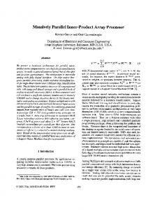
Fig. 1. Block diagram of one row in the matrix with binary encoded elements w ; ( ~ - ~for ) ,a single rn and with I = 4 bits. Data flow of bit-serial inputs z j ( n ) and corresponding partial outputs y i , j (m), with J = 4 bits.
in a mutli-chip architecture. Conclusions are presented in Section V.
ments, and J-bit encoding of inputs: I-1
11. MIXED-SIGNAL ARCHITECTURE A. Internally Analog, Externally Digital Computation
J
j=O
The system presented is internally implemented in analog VLSi technology, but interfaces externally with the digital world. This paradigm combines the best of both worlds: it uses the efficiency of massively parallel analog computing (in particular: adding numbers in parallel on a single wire), but allows for a modular, configurable interface with other digital pre-processing and post-processing systems. This is necessary to make the processor a general-purpose device that can tailor the vector-matrix multiplication task to the particular application where it is being used.
decomposing (1) into:
The digital representation is embedded, in both bit-serial and bit-parallel fashion, in the analog array architecture (Fig. 1). Inputs are presented in bit-serial fashion, and matrix elements are stored locally in bit-parallel form. Digital-to-analog (D/A) conversion at the input interface is inherent in the bit-serial implementation, and row-parallel analog-to-digital ( A D )converters are used at the output interface.
The proposed mixed-signal approach is to compute and accumulate the binary-binary partial products (5) using an analog VMM array, and to combine the quantized results in the digital domain according to (4).
For simplicity,an unsigned binary encoding of inputs and matrix elements is assumed here, for one-quadrant multiplication. This assumption is not essential: it has no binding effect on the architecture and can be easily extended to a standard one's complement for four-quadrant multiplication, in which the significant bits (MSB) of both arguments have a negative rather than positive weight. Assume further I-bit encoding of matrix ele-
392
I-1 .I-I
N-1
N-1
n=O
B. Array Architecture and Data Flow To conveniently implement the partial products (5), the binary encoded matrix elements wi(m+) are stored in bit-parallel form, and the binary encoded inputs are presented in bit-serial fashion. The bit-serial format was first proposed and demonstrated in [8], with binary-analog partial products using analog matrix elements for higher density of integration. The use of binary encoded matrix elements relaxes precision requirements and simplifies storage [9].
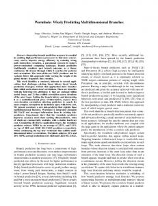
with common m and i indices. The circuit diagram and operation of the cell are given in Figure 2. An array of cells thus performs (unsigned) binary multiplication ( 5 )of matrix wi(min) and vector zj(n)yielding y i , j ( m ) , for values of i in parallel across the array, and values of j in sequence over time. The cell contains three MOS transistors connected in series as depicted in Figure 2. Transistors M1 and M2 comprise a dynamic random-access memory (DRAM) cell, with switch M1 controlled by Row Select signal I?&(”). When activated, the binary quantity wi(m*n)is written in the form of charge stored under the gate of M2. Transistors M2 and M3 in turn comprise a charge injection device (CID), which by virtue of charge conservation moves electric charge between two potential wells in a non-destructivemanner [8], 191, [15]. The cell operates in two phases: Write and Compute. When a matrix element value is being stored, zj(n)is held at V d d and V o u t at a voltage V d d / 2 . To perform a write operation, either an amount of electric charge is stored under the gate of M2, if wi(min) is low, or charge is removed, if wi(m~n) is high. The amount of charge stored, AQ or 0, corresponds to the binary value wi(*+). Once the charge has been stored, the switch M1 is deactiFig. 2. CID computational cell with integrated DRAM storage (fop). Charge vated, and the cell is ready to compute. The charge left under transfer diagram for active write and compute operations (bottom). the gate of M2 can only be redistributed between the two CID transistors, M2 and M3. An active charge transfer from M2 to One row of I-bit encoded matrix elements uses I rows of bi- M3 can only occur if there is non-zero charge stored, and if the nary cells. Therefore, to store an M x N digital matrix W(min), potential on the gate of M2 drops below that of M3 [8]. This an array of M I x N binary cells is needed. One bit of condition implies a logical AND, i.e., unsigned binary multiplian input vector is presented each clock cycle, taking J clock cy- cation, of wi(m*n)and zj(”). The multiply-and-accumulateopcles of partial products ( 5 ) to complete a full computational cy- eration is then completed by capacitively sensing the amount of cle (1). The input binary components zj(n)are presented least charge transferred onto the electrode of M3, the output summing significant bit (LSB) first, to facilitate the digital postprocessing node. To this end, the voltage on the output line, left floating afto obtain (4) from ( 5 ) (as elaborated in Section IV). ter being pre-charged to V d d / 2 , is observed. When the charge Figure 1 depicts one row of matrix elements W(m*fl) in the transfer is active, the cell contributes a change in voltage binary encoded architecture, comprising I rows of binary cells Avo,, = A Q / C M ~ (6) where I = 4 in the example shown. The data flow is illustrated for a digital input series zj(n)of J = 4 bits, LSB first where Cll.13 is the total capacitance on the output line across (i.e., descending index j ) . The corresponding analog series of cells. The total response is thus proportional to the number of outputs yi,j(m)in ( 5 ) obtained at the horizontal summing nodes actively transferring cells. After deactivating the input ~ j ( ~ ) , of the analog array is quantized by a bank of analog-to-digital the transferred charge returns to the storage node M2. The CID converters (ADC), and digital postprocessing (4) of the quan- computation is non-destructive and intrinsically reversible [8], tized series of output vectors yields the final digital result (1). and DRAM refresh is only required to counteract junction and The quantization scheme used is critical to system perfor- subthreshold leakage. mance. As shown in Section IV, appropriate postprocessing The bottom diagram in Figure 2 depicts the charge transfer in the digital domain to obtain (4)from the quantized partial timing diagram for write and compute operations in the case can lead to a significant enhancement in sys- when both wi(m~n) products and zj are of logic level 1. A logic level tem resolution, well beyond that of intrinsic ADC resolution. 0 for wi(myn) is represented as V d d , and a logic level 1 is repreThis relaxes precision requirements on the analog implementasented as V d d / 2 , where V d d is the supply voltage. For zj(*), tion of the partial products (5). A dense and efficient charge- logic level 0 is represented as V d d , and logic level 1 as GND. mode VLSI implementation is described next. Transistor-level simulation of a 5 12-element row indicates a
x,j(m)
111. CHARGE-MODE VLSI IMPLEMENTATION A. CID/DRAM Cell and Array
The elementary cell combines a CID computational unit [8], [93, computing one argument of the sum in (3, with a DRAM storage element. The cell stores one bit of a matrix element wi(m’n),performs a one-quadrant binary-binary multiplication ) , accumulates the result across cells of wi(myn) and ~ j ( ~and
dynamic range of 43 dB, and a computational cycle of 10 ps with power consumption of 50 nW per cell. Experimental results from a fabricated prototype are presented next. B. Experimental Results
We designed, fabricated and tested a VLSI prototype of the vector-matrix multiplier, integrated on a 3 x3 mm2 die in 0.5 pm CMOS technology. The chip contains an array of 512 x 128
393
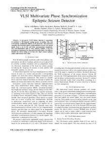
Fig. 4. Measured linearity of the computational array. The number of active charge-transfer cells is swept in increments of 64,with the analog voltage output on the sense line shown on the top scope trace.
dressed below. Fig. 3. Micrograph of the mixed-signal VMM prototype, containing an array of 512 x 128 CIDDRAM cells, and a row-parallel bank of 128 Rash ADCs. Die size is 3 rnrn x 3 rnm in 0.5 pm CMOS technology.
CIDDRAM cells, and a row-parallel bank of 128 gray-code flash ADCs. Figure 3 depicts the micrograph and system floorplan of the chip. The layout size of the CIDDRAM cell is 8X x 45X with X = 0.3pm. The mixed-signal VMM processor interfaces externally in digital format. Two separate shift registers load the matrix elements along odd and even columns of the DRAM array. Integrated refresh circuitry periodically updates the charge stored in the array to compensate for leakage. Vertical bit lines extend across the array, with two rows of sense amplifiers at the top and bottom of the array. The refresh alternates between even and odd columns, with separate select lines. Stored charge corresponding to matrix element values can also be read and shifted out from the chip for test purposes. All of the supporting digital clocks and control signals are generated on-chip. Figure 4 shows the measured linearity of the computational array. The number of active cells on one row transferring charge to the output line is incremented in steps of 64. The case shown is where all binary weight storage elements are actively charged, and an all-ones sequence of bits is shifted through the input register, initialized to all-zeros bit values. For every shift of 64 positions in the input, a computation is performed and the result is observed on the output sense line. The experimentally observed linearity agrees with the simulation results presented in Section 111-A. The chip contains 128 row-parallel 6-bit flash ADCs, i.e., one dedicated ADC for each m and i. In the present implementation, Y ( m is ) obtained off-chip by combining the ADC quantized outputs X,j(") over i (rows) and j (time) according to (4). Issues of precision and complexity in the implementation of (4) are ad-
394
Iv. QUANTIZATION A N D DIGITAL RESOLUTION ENHANCEMENT A. Accumulation and Quantization
Significant improvements in precision can be obtained by exploiting the binary representation of matrix elements and vector inputs, and performing the computation (4) in the digital domain, from quantized estimates of the partial outputs ( 5 ) . We quantize all I x J values of K,~(" )using row parallel flash A/D converters. Figure 5 presents the corresponding architecture, shown for a single output vector component m. The partials summation is then performed in the digital domain:
=
c
K-1
1-1 J-1
&("I
2-(2+3+2)&(") 2 J
=
2-(
k+2)
Q""' k
1
(7)
k=O
a=O j=O
wherek = i + j , K = I + J - 1and k --K ( k,I ) &'(") k
Q$?,
= %Z:K(
=
(8)
k,J)
+
with ~ ( kI ), max(0, Ic - I 1) and ~ ( kJ ,) E max(0, k J 1).A block diagram for a digital implementation is shown on the right of Figure 5. As shown in [ 161, the effect of averaging the quantization error over a large number of quantized values of K,3(m)boosts , the intrinthe precision of the digital estimate of Y ( m )beyond sic resolution of the analog array and the A/D quantizers used. We obtain an improvement in signal-to-quantization-noise ratio of a factor 3 and a median resolution gain of approximately 2 bits over the resolution of each ADC.
+
B. Multi-Chip System with Offset Compensation Other significant sources of error in analog array-based computation are input-dependent feedthrough, and input and timedependent charge leakage in DRAM storage cells introducing
Fig. 5. Diagram for the AID quantization and digital postprocessing block in Figure 1, using row-parallel flash AID converters. The example shown is for a single m, LSB-first bit-serial inputs, and I = J = 4.
offsets. Both of these errors are compensated for in a multichip VMM architecture by m$ng one reference chip supplied with identical inputs, synchronous refresh clock and all logic “0’matrix elements. Subtraction of outputs of equivalent rows in digital domain eliminates both input-dependent and temporal errors as shown in detail in 1171. V. CONCLUSIONS
A charge-mode VLSI array processor for matrix operations in large dimensions ( N , M = 100-10,000) has been presented. The architecture embeds storage and multiplication in distributed fashion, down to the cellular level. With only three transistors, the cell for multiplication and storage contains little more than either a DRAM or a CID cell. This makes the analog cell very compact and low power, and the regular array of cells provides for a scalable architecture that can easily be extended. Fine-grain massive parallelism and distributed memory provide computational efficiency (bandwidth to power consumption ratio) exceeding that of digital multiprocessors and DSPs by several orders of magnitude. A 512 x 128 VMM prototype fabricated in 0.5 pm CMOS offers 2 x 10l2binary MACS (multiply accumulates per second) per Watt of power.
REFERENCES J.C. Gealow and C.G. Sodini, “A Pixel-Parallel Image Processor Using Logic Pitch-Matched to Dynamic Memory,’’ IEEE J. Solid-State Circuits, vol. 34,pp 831-839, 1999. Y. Fujita, S.A. Kyo, et. al., 10 GIPS SIMD processor for PC-based real time vision applications -architecture, algorithm implementation and language support,” Proc. of IEEE International Workshop on Computer Architecturefor Machine Perception, CAMP 97.,pp. 22-32, 1997. D.G.Elliott, M. Stumm, et. al., “Computational RAM: implementing processors in memory,” IEEE Design & Test of Computers, vol. 16 (1). pp. 3241, 1999. A. Amira, A. Bouridane, et. al., “A high throughput FPGA implementation of a bit-level matrix product,” IEEE Workshop on Signal Processing Systems, SiPS 2000, pp. 356-364.2000. A. Kramer, “Array-based analog computation,” IEEE Micro, vol. 16 (5), pp. 40-49, 1996. P. Pouliquen. A.G. Andreou, K. Strohbehn “Winner-takes-all associative
memory: a hamming distance vector quantizer,” Journal of Analog Integrated Circuits and Signal Processing, vol. 13, pp. 21 1-222, 1997. A. Chiang, “A programmable CCD signal processor,” IEEE Journal of Solid-state Circuits, vol. 25 (6). pp. 1510-1517, 1990. C. Neugebauer and A. Yariv, “A Parallel Analog CCD/CMOS Neural Network IC,” Proc. IEEE Int. Joint Conference on Neural Networks (IJCNN’91). Seattle, WA, vol. 1,pp 447-451, 1991. V. Pedroni, A. Agranat, C. Neugebauer, A. Yariv, “Pattern matching and parallel processing with CCD technology,” Proc. IEFE Int. Joint Conference on Neural Networks (IJCNN’92), vol. 3, pp 620-623, 1992. G. Han, E. Sanchez-Sinencio, “A general purpose neuro-image processor architecture,” Proc. of IEEE Int. Symp. on Circuits and Systems (ISCAS’96). vol. 3, pp 495-498, 1996. M. Holler, S. Tam, H. Castro and R. Benson, ”An Electrically Trainable Artificial Neural Network (ETANN) with 10,240 Floating Gate Synapses,” in Proc. Int. Joint Conf Neural Networks, Washington DC. pp 191-196, 1989. F. Kub, K. Moon, I. Mack, F. Long, “ Programmable analog vector-matrix multipliers,” IEEE Journal of Solid-State Circuits, vol. 25 (1). pp. 207214, 1990. G. Cauwenberghs, C.F. Neugebauer and A. Yariv. “Analysis and Verification of an Analog VLSI Incremental Outer-Product Learning System,” IEEE Trans. Neural Networks, vol. 3 (3). pp. 488-497, May 1992. A.G. Andreou, K.A. Boahen, P.O. Pouliquen, A. Pavasovic, R.E. Jenkins, and K. Strohbehn, “Current-Mode Subthreshold MOS Circuits for Analog VLSI Neural Systems,” IEEE Transactions on Neural Networks, vol. 2 (2). pp 205-213, 1991. M. Howes, D. Morgan, Eds., Charge-Coupled Devices and Systems, John Wiley & Sons, 1979. R. Genov and G. Cauwenberghs, “Charge-Mode Parallel Architecture for Matrix-Vector Multiplication:’ Proc. 43rd IEEE Midwest Symp. Circuits and Systems (MWSCAS’2000). Lansing MI, August 8-11,2000. R. Genov. G. Cauwenberghs, “Analog Array Processor with Digital Resolution Enhancement and Offset Compensation,” Proc. of Conf on Information Sciences and Systems (CISS’2001).Baltimore, MD 2001:
395 -