Circular interpretation of bijective transformations is proposed ... tivate the use of lossless watermarking in medical environment. ⢠Since the ..... Press, 1992, ch.
IEEE TRANSACTIONS ON MULTIMEDIA, VOL. 5, NO. 1, MARCH 2003
97
Circular Interpretation of Bijective Transformations in Lossless Watermarking for Media Asset Management Christophe De Vleeschouwer, Jean-François Delaigle, and Benoît Macq, Senior Member, IEEE
Abstract—The need for reversible or lossless watermarking methods has recently been highlighted to associate subliminal management information with losslessly processed media and to enable their authentication. This paper first analyzes the specificity and the application scope of lossless watermarking methods. It explains why early attempts to achieve reversibility are not satisfactory. They are restricted to well-chosen images, strictly lossless context and/or suffer from annoying visual artifacts. Circular interpretation of bijective transformations is proposed to implement a method that fulfills all quality and functionality requirements of lossless watermarking. Results of several bench tests demonstrate the validity of the approach. Index Terms—Data hiding, data management, image processing, watermarking.
I. INTRODUCTION
D
IGITAL watermarking aims at hiding data directly into media contents. Originally, watermarking was designed to meet copyright protection requirements [1]–[3]. It soon proved to be attractive to convey metadata, enabling content indexing, management, and tracing [4], [5]. This technique has also been extended to control content integrity and authentication [6]–[8]. It is then referred to as fragile watermarking. The use of a watermark for authentication purposes raises an important problem: as the watermark modifies pixel values, it also prevents strict integrity control. To circumvent the problem, the watermarking process has to be reversible, i.e., it must be possible to recover the original image from the watermarked one. In that sense, reversible watermarking is a lossless process. Reversible and lossless are used as synonyms in the following. Besides enabling strict integrity control, lossless watermarks also enlarge the scope of watermarking-based systems to any visual content stored or transmitted in a lossless (or reversible or noiseless) fashion. Lossless image processing [9] is required in applications where pictures are subject to further processing, e.g., to extract specific information through extreme zoom. It is also desired for images obtained at great cost, or in applications where the quality desired for the rendering is still unknown. Medical imaging, prepress industry, image archival systems, precious artworks, military images, and remotely sensed images are all candidates for lossless processing, and in particular for lossless watermarking.
Manuscript received August 27, 2002; revised January 31, 2003. This work was supported by the Belgian NFS. The associate editor coordinating the review of this paper and approving for publication was Dr. Ahmed Tewfik. The authors are with the Université Catholique de Louvain, 1348 Louvain-laNeuve, Belgium. Digital Object Identifier 10.1109/TMM.2003.809729
The medical environment conveniently illustrates how applications can benefit from lossless watermarking. In hospitals, electronic patient records (EPRs) are gathered by numerous of health professionals and are used for various purposes (patient care but also clinical research, or risk evaluation by insurance companies) [10]. Fragile watermarking enables authentication and integrity control of such EPR’s. A lossless watermark can also be used to link metadata to EPR’s. A number of reasons motivate the use of lossless watermarking in medical environment. • Since the watermark payload is inseparably embedded into the media content, its manipulation does not require any explicit actions by the medical staff. This is an interesting feature if one notices that, in hospitals, a large proportion of authentication problems are not due to any intrusion, but rather to errors in the manual entry of patient data [11]. • The possibility to recover the original image enables designers to build a strictly lossless system. This is crucial for a medical imaging system [12], [13], since the diagnosis can not be disturbed in any way without running the risk of legal indictments. • Medical images often go through several services and are subject to different processing and annotations. These transformations are recorded in a historical summary, which is attached to the image as metadata. To authenticate both the image and the record content, the watermark has to be modified accordingly. Reversible watermark enables authorized workstations to access the original image and to embed an updated watermark. • Finally, it is worth noting that robustness to image processing still makes sense in the context of reversible watermarking. It might enlarge the scope of reversible watermarks as it enables the lossless watermark to convey information in lossy environment. An example is the transmission of a compressed version of the image to the family doctor without losing embedded management information. Historically, reversible watermarks were first introduced as a visible pattern by Mintzer et al. in [14]. In their digital library application, images are marked with a reversible and visible watermark before posting them on the Internet. The watermarked image serves as a teaser that users may obtain for free. A “vaccine” program, available for an additional fee, removes the watermark and reconstructs the original image. The concept of lossless invisible watermarks first appeared in a patent owned by The Eastman Kodak [15]. Modulo operations complete an existing additive method to ensure reversibility. The same idea has been proposed in [16] to extend the patchwork algorithm [17]. However, these approaches are not satisfactory. The wrapped
1520-9210/03$17.00 © 2003 IEEE
98
IEEE TRANSACTIONS ON MULTIMEDIA, VOL. 5, NO. 1, MARCH 2003
Fig. 1. Symmetric key authentication system.
around pixels cause annoying “salt-and-pepper” visual artifacts. Worse, as the watermark retrieval relies on magnitude comparison, these methods can not deal with images or blocks that contain many wrapped around values. To avoid these problems, Fridrich et al. [18] propose to replace a bit plane of the image to be watermarked. A full bit plane is extracted and losslessly compressed. The created space is then filled up with the watermark payload. The disadvantage of this method is the fact that the capacity varies from image to image. Often, more than one bit plane is needed, leading to disturbing artifacts. Moreover, the usage of Fridrich’s method is strictly restricted to lossless environment. Once a watermarked image is lossly processed, a single bit modification in the bitplane carrying the watermark payload breaks the entropy decoder synchronization. The information can not be retrieved anymore. The paper is organized as follows. Section II presents the architecture of envisioned lossless watermarking systems. Section III proposes a novel approach to lossless watermarking that does not suffer from the drawbacks of existing methods. Similarly to the patchwork algorithm, two pseudo-random sub-regions of a block are transformed in opposite directions. The pixel transformation is bijective to ensure reversibility. It is interpreted as a rotation on a circle that supports the luminance space, so that the embedded information can be extracted from the relative position of the two pseudo-random histograms on that circle. The circular interpretation of the transformation is probably the key idea of the method. As the luminance values are uniformly distributed on the circle, all pixel values are strictly equivalent from the transformation point of view. It guarantees the coherence of the transformation interpretation and, consequently, ensures total reversibility. Section IV presents the performance of our method in terms of capacity and distortion. It validates the approach. Despite the method has been primarily designed for lossless environments, Section IV also considers its use in two particular lossy systems. It shows that the method is robust to JPEG compression and that the embedded grid alignment can be recovered for cropped images. Section V concludes. II. LOSSLESS WATERMARK SYSTEMS ARCHITECTURE A. Database Management Systems As any other watermark, a lossless watermark conveys metadata information, which enables a range of applications such as IPR’s identification, content indexing, management and usage
Fig. 2. Asymmetric key authentication system.
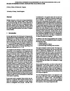
Fig. 3. Histogram mapping around a circle: Each position on the circle corresponds to a 4-bit luminance value. A virtual mass whose weight is proportional to the luminance occurrence is fixed at each position.
or history tracing [4], [5]. The reversibility feature extends the scope of these applications to lossless systems. B. Authentication Systems In a strict authentication system, the change of a single bit invalidates the integrity control, making no difference between malevolent and nonmalevolent content manipulations. Strict authentication systems based on watermarking are only possible using lossless watermarks. Such systems can be either symmetric or asymmetric. It is worth noting that for both systems the input image might be either the whole image or part of it. Independent authentication of nonoverlapping regions, e.g., blocks, of the image provides localized detection of image modifications. 1) Symmetric Authentication System: The hashing function, such as the popular MD5 [19], is classically used to provide strict integrity control. In the system shown in Fig. 1, the hash of the image (or part of the image) generates the message that is embedded into the original image. A secret key is used to disable any attempt to remove or replace the message. This system is labeled as symmetric because the same key is used for embedding and extracting the watermark message. It is closed in the sense that only authorized persons possess this key and can access the watermark to check integrity. For this purpose, the original image is retrieved from the inversion process and its hash value is compared with the extracted watermark message. 2) Asymmetric Authentication System: The asymmetric system allows any user to check the integrity of a watermarked image. In Fig. 2, the key used for watermark generation is a public seed, known to all users. Prior to embedding, the hash of
DE VLEESCHOUWER et al.: CIRCULAR INTERPRETATION OF BIJECTIVE TRANSFORMATIONS
99
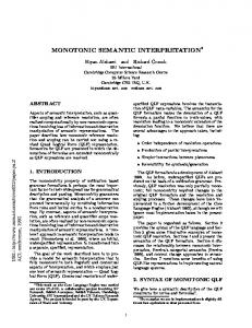
Fig. 4. Embedding method illustration: pixels of each pseudo-random zone are transformed according to sequence (a) and (b). The transformation is interpreted as a rotation that changes the positions of the center of mass of the circular histogram of each pseudo-random zone. The relative position of these centers of mass conveys the embedded information.
the image is signed by a cryptographic signature process [20]. The resulting signature is the embedded message. The system is open in the sense that any user can access the watermark and check the integrity. As for the closed system, the original image can of course be recovered from the inversion process. III. ROTATION OF CIRCULAR HISTOGRAM LOSSLESS WATERMARKING
FOR
A. Reversible Embedding: Patchwork Histogram Rotation The embedding process hides a binary message, i.e., the watermark payload, into a picture. Each bit of the message is associated with a group of pixels, e.g., a block in the image. Each group is equally divided into two pseudo-random sets of pixels, i.e., zones and , as for the patchwork algorithm [17]. are increIn patchwork, pixels belonging to zone pixels are respectively decremented/decremented while and are pseudo-ranmented/incremented. Since zones domly generated, they have close average values before embedding. After embedding, depending on the bit to embed, their luminance values are incremented or decremented. The extracted bit is inferred from the comparison between the mean values of zone and . To make the process reversible for 8-bit gray scale images, Macq has implemented additions and subtractions with modulo 256 [16]. Modulo operations introduce a disturbing visual artifact similar to a “salt-and-pepper” noise
when pixels close to the maximally allowed value are flipped to zero and vice versa. Worse, once flipped, values that should be increased (decreased) are actually decreased (increased), which dramatically impacts the average value of the zone, and consequently the inferred bit. Wrapped around pixels distort the retrieval process and in the sequel the inversion process. In our method, the average luminance value of each zone is not the discriminating factor. The histogram of the gray scale or luminance values of each zone is mapped to a circle and the position of the histogram on the circle replaces the concept of average value. In concrete terms, a weight proportional to the occurrence of each luminance value is placed on the corresponding position on the circle (see Fig. 3). The position of the center of mass (or the orientation of the principal axes in Section III-C) of the resulting distribution of weights replaces the concept of mean value. The embedding method is summarized in Fig. 4. The histogram of each zone is mapped to a circle according to and point to the center of mass of zones Fig. 3. Vectors and , respectively named and . These vectors define the positions of each histogram. As zones and are pseudo-randomly generated and have equal size, it is highly probable that and are close to each other. Slight rotations of these vectors in opposite ways allow for embedding a bit of information. either clockwise (to embed a “1”) or The rotation pushes anti-clockwise (to embed a “0”). At the receiver, the bit is inferred from the sign of the smallest angle between vectors
100
IEEE TRANSACTIONS ON MULTIMEDIA, VOL. 5, NO. 1, MARCH 2003
Fig. 6. Alternative mapping of the histogram to the circle: The positions of luminance values on the circle are chosen so that all neighbors correspond to close luminance values. It prevents “salt-and-pepper” effect after rotation.
mark payload enables reversibility of these pathological blocks. B. Extraction and Inversion Processes
Fig. 5. Problematic cases. The cross represents the circle center. A square corresponds to the center of mass of a pseudo-random histogram. Case (a) is not depicted. It occurs when the center of mass coincides with the circle center. Embedding is not possible. The receiver observes the same configuration and concludes the block has not been modified. In case (b), = (V ; V ) 2:�, � being the embedding rotation angle. � is too small to swap V and V . The block can not carry information. Pixels of zones A and B are shifted to open the angle between vectors V and V . The receiver notices that 4:�, being (V ; V ) after embedding and reverses the embedding by shifting pixels to bring the vectors closer to each other. In case (c), after embedding, � 2:�. The received block can result from two different source blocks and the receiver needs additional knowledge to reverse the embedding.
�
�
� 0
and . At the pixel level, rotations of vectors correspond to luminance shifts. Pixels are shifted according to sequence (b) or (a) in Fig. 4 to induce a clockwise or anti-clockwise rotation of the vector. The magnitude of the shift, also called the embedding level, directly impacts the rotation angle. As the transformation is bijective, once the rotation direction is known, it is reversible. This direction, which also defines the retrieved bit, is inferred and . from the relative angular positions of vectors Note that the method relies on the fact that the vectors and are close to each other before embedding. This is highly probable, since the zones have equal sizes and are pseudo- randomly selected. However, some particular cases are possible. They are considered in Fig. 5. Cases (a) and (b) correspond to blocks that cannot carry any information. Vectors and are either undefined or too open. In both cases, the problem is also observed while extracting the watermark and the original block can be recovered without a priori knowledge. Case (c) is more problematic. In that case, the problem is still detectable on the receiver side but reversibility relies on additional knowledge. Note that only the inversion of the embedding relies on additional knowledge, not the information decoding or extraction process. The decoder deduces from and configuration that the block does not carry information. The extracted information is reliable by itself and can thus convey the additional knowledge needed for reversibility. So, case (c), which is very rare in practice, is not a real drawback of the method. On the embedding side, case (c) is just treated as case (b). It does not carry embedded information. On the receiver side, additional information extracted from the water-
The extraction process consists first in partitioning the image and , similarly to the embedding into blocks and zones process. Histograms of each zone are mapped to the circle. For both zones, the center of mass is computed. Let be the angle between the vectors and , pointing from the circle center to each center of mass. The magnitude of differentiates problematic blocks (see Fig. 5) from others. The sign of provides the direction of rotation during the embedding process and enables bit retrieval and reversibility. Once the embedded bit has been retrieved, the original block can be recovered. This is called the inversion process, it consists in following the embedding process depicted in Fig. 4 in the reverse order. C. Solution to the “Salt-and-Pepper” Artifacts In Fig. 4, the shifts of luminance caused by sequence (a) and (b) are equivalent to modulo additions or subtraction. A major advantage of our approach is that it avoids unreliable retrieval caused by the impact of wrapped around pixels on average values. Nevertheless, our method is not free from salt-andpepper artifact. In order to prevent it, an alternative mapping of the histogram to the circle is proposed in Fig. 6. At the circle level, the embedding transform is still the same, i.e., a rotation (see Fig. 7). However, at the pixel level (see sequence (a) and (b) on Fig. 7), no value is shifted by an outstanding large step anymore. The transform is now free from disturbing visual artifact such as the “salt-and-pepper” effect. The change in the transform somewhat impacts the retrieval process. In Fig. 6, odd and even luminance values are spread symmetrically around the circle. As a result, the histogram is also spread symmetrically around the circle and the center of mass is close to the vertical axis of symmetry. For intermediate luminance values (around 7 in Fig. 6), the center of mass is close to the circle center. Pathological cases (see Fig. 5) become more frequent in that configuration. To reduce the impact of these cases on the system performances, another retrieval method is considered. The vector pointing to the center of mass does not indicate the position of the histogram on the circle anymore. The direction of the principal axis with minimal inertia is used instead. Embedding and retrieval procedures are similar to the ones described previously, with similar unlikely pathological cases.
DE VLEESCHOUWER et al.: CIRCULAR INTERPRETATION OF BIJECTIVE TRANSFORMATIONS
101
Fig. 7. Embedding illustration when impeded by salt-and-pepper effect: pixels of each zone are transformed according to sequence (a) and (b); it impacts the principal axis orientation.
IV. METHOD EVALUATION This section measures the performance of our method in terms of capacity and distortion. It validates the proposed approach. Then, despite the method has been primarily designed for lossless environments, two particular lossy systems are considered. It shows that the method is robust to JPEG compression and that the embedding grid alignment can be recovered for cropped images. The results have been gathered from four images, Lena and three typical medical images (see Fig. 8), using different block sizes (4 4, 8 8, and 16 16) and different embedding levels. Here, the embedding level is equivalent to distortion. It measures the magnitude of the luminance shift. A. Capacity versus Distortion The capacity, expressed in bits/pixel, measures the number of bits conveyed by the watermark. Referring to Fig. 5, a nonprob-
lematic or regular block carries one bit of information, blocks of cases (a) and (b) do not convey or cost anything, while a block of case (c) costs one bit to be correctly reversed. and being respectively image width and height, capacity is computed in bits/pixel by
(1) Table I presents the distribution of the image blocks into three categories. The first category contains the nonproblematic or regular blocks, the second considers the blocks that bring nothing to capacity, and the last counts the blocks that cost one bit. The distribution is provided for an embedding level equal to 4 and illustrates the dependency of the capacity on image content and block size. Fig. 9 shows how capacity depends on the embedding level for different block sizes. It first appears that the bandwidth is larger for small blocks than for large ones. We conclude that
102
IEEE TRANSACTIONS ON MULTIMEDIA, VOL. 5, NO. 1, MARCH 2003
2
Fig. 8. The test bench used for evaluation. (a) Lena (256 256), (b) computed Tomography (449 263), (c) ultrasound (459 357), and (d) radiograph (400 490).
2
2
2
Fig. 9. Capacity in bits/pixel for the method described in Fig. 4. It is expressed for a set of embedded block sizes as a function of the embedding level: (a) capacity for Lena and (b) average capacity for the three medical images of the test bench.
TABLE I NUMBER OF BLOCKS USED TO INFER THE CAPACITY. EMBEDDING LEVEL HAS BEEN SET TO 4, AND TEST BENCH IMAGES ARE CONSIDERED. THE LAST THREE COLUMNS CORRESPOND RESPECTIVELY TO THE REGULAR BLOCKS, TO THE BLOCKS THAT DO NOT AFFECT THE CAPACITY, AND TO THE BLOCKS THAT COST ONE BIT OF CAPACITY
reducing the block size does not dramatically increase the proportion of problematic blocks. Second, for a fixed block size, capacity increases with the embedding level. This means that the number of problematic blocks decreases when the embedding level increases. The trend is more obvious when the block size is small, i.e., when problematic blocks are more frequent. Fig. 10 illustrates the validity of the solution proposed to the “salt-and-pepper” artifact. It presents two watermarked versions of the same medical image. The embedding level is the same for both images (equal to 2). The one on the top of Fig. 10 has been modified according to Fig. 4. It suffers from a very annoying “salt-and-pepper” artifact. The one at the bottom makes use of the transformation described in Fig. 7. Visual quality is largely improved. Fig. 11 analyzes the capacity of the watermarking system using the transform proposed as a solution to the “salt-and-
Fig. 10. “Salt-and-pepper” illustration. A medical image is transformed according to Fig. 4 (on the top) and Fig. 7 (at the bottom), using the same embedding level.
DE VLEESCHOUWER et al.: CIRCULAR INTERPRETATION OF BIJECTIVE TRANSFORMATIONS
103
(a)
2
Fig. 12. Exhaustive search of the proper grid alignment for a 256 256 cropped image. The size of the embedded blocks increases from top to bottom (4, 8, 16). The embedding level increases from left to right (2, 4, 8). Each graph plots, as a function of the grid alignment, the average of the absolute normalized angular value measured between the pseudo-random histograms of each image block.
(b) Fig. 11. Analysis of the method described in Section III-C to solve the “salt-and-pepper” artifact. Capacity (in bits/pixel, averaged on the image test bench) is expressed as a function of the embedding level. Two factors are considered to define the position of the circular histogram on the circle. (a) The center of mass (similar to Fig. 4) and (b) the principal axis with minimal inertia (Fig. 7).
pepper” artifact in Section III-C. For this transform, the capacity available when considering the angle between the vectors pointing to the center of mass is compared with the capacity obtained with the principal axes orientations. Problematic cases are much more likely, and the capacity much smaller when considering the center of mass rather than the principal axis. As explained in Section III-C, this is due to the fact that, for this mapping, the center of mass is often close to the circle center. B. Coping With Lossy Systems 1) Cropped Image Synchronization: In a pure lossless environment, by convention, the grid of embedded blocks originates at the top left-hand corner of the image, and synchronization is trivial. However, for a system capable of supporting image cropping, grid alignment becomes an issue. The recovery of a fragment of the watermark payload might, for example, be useful to perform the inversion process on the cropped image, or to check its integrity (under the assumption that the blocks of the image have been authenticated independently). As illustrated in Figs. 12 and 13, the proper grid alignment can be recovered from an exhaustive search. Each possible alignment defines a set of blocks on the cropped image. Each block is partitioned into two key-dependent pseudo-random zones that are mapped onto the circular histogram. The angle between these two zones is expected to be zero in case the of wrong alignment. However, it is expected to be either positive or negative and proportional to the embedding level when the block is properly aligned. The
2
Fig. 13. Exhaustive search of the proper grid alignment for a 64 64 cropped image. The size of the embedded blocks increases from top to bottom (4, 8, 16). The embedding level increases from left to right (2, 4, 8). Each graph plots, as a function of the grid alignment, the average of the absolute normalized angular value measured between the pseudo-random histograms of each image block.
average of the absolute values of these angles allows for synchronization. Figs. 12 and 13 plot the average of the absolute values as a function of the grid alignment. The average has been normalized by the rotation angle corresponding to an embedding level equal to one. A very sharp peak points out the correct alignment. The larger the cropped image, the easier the synchronization. At constant image size, the size of the embedded blocks does not really impact the synchronization capability. 2) JPEG Robustness: In [18], the alteration of a single bit of the watermarked image is sufficient to make the retrieval of the embedded message impossible. This method is therefore strictly constrained to lossless environment. Being able to convey the embedded information through lossy environment might however be useful in some application scenarios, e.g., when the same
104
IEEE TRANSACTIONS ON MULTIMEDIA, VOL. 5, NO. 1, MARCH 2003
reversible algorithm by circular interpretation of bijective transformations. The histograms of groups of pixels are mapped to a circle. The transform is chosen so as to provoke the rotation of the histograms around the circle. The relative orientation of the histograms of two groups of pixels conveys one bit of information. Our method clearly outperforms and differs from the results achieved in the past [15], [16], [18]. Its performance and reliability are not burdened by particular luminance values. The retrieval of the embedded information and, consequently, the reversibility process are not altered by wrapped around pixels. Additionally, the visual quality of the watermarked images does not suffer from the classic “salt-and-pepper” artifact. Finally, the extraction of the complete embedded message is still possible after alteration of the watermarked image. This robustness permits conveying embedded information from lossless to lossy environments. Fig. 14. Robustness illustration. A 100-bit message is repeatedly embedded using the method depicted in Fig. 4. The graph presents the average number of correctly decoded bits as a function of the JPEG compression level.
medical image is transmitted both to the specialist (lossless processing is required) and to the family doctor (lossy compression in tolerated). Our approach offers such capability. It is robust in the sense that the efficiency of the retrieval process degrades gracefully as a function of the image alteration. Fig. 14 considers a simple scenario to illustrate the robustness of the method depicted in Fig. 4. A message of 100 bits is embedded in an image using a constant embedding level ( 4). Message repetition combined with a decision by majority provides a trivial error correction scheme. The watermarked image is then compressed using a JPEG algorithm. For different block sizes and different compression levels, the number of bits that are correctly retrieved is averaged over the test bench images and plotted on Fig. 14. It appears that the efficiency of the retrieval process degrades gracefully with the JPEG quality factor. For low compression levels (high quality factors), a large number of small blocks perform better than a small number of large blocks. For high compression levels (low quality factors), the retrieval at block level is strongly distorted for small blocks, so that repetition does not help anymore. It is preferable to use large blocks to cope with high compression ratios. Note also that only the method depicted in Fig. 4 is robust. The method proposed in Fig. 7 is appealing from a perceptual point of view, but is restricted to lossless environments. Slight random shifts of the luminance values distribute the pixels equally on both sides of the circular histogram and erase the information in lossy environment. V. CONCLUSIONS Reversible or lossless watermarking enables strict integrity control of media content without resort to proprietary or standardized constraining labeling processes. Reversibility also enlarges the scope of any media asset management system based on watermarking. It opens the door to strictly lossless contexts, of which the medical imaging environment is the clearest example. This paper proposes an original implementation of such a
REFERENCES [1] A. Z. Tirkel, G. A. Rankin, R. M. van Schyndel, W. J. Ho, N. R. A. Mee, and C. F. Osborne, “Electronic water mark,” in Digital Image Computing, Technology and Applications (DICTA’93). Sidney, Australia, 1993, pp. 666–673. [2] G. Caronni, “Assuring ownership rights for digital images,” in Proc. Reliable IT Systems, VIS 95, Germany, June 1995. [3] I. J. Cox, J. Kilian, T. Leighton, and T. Shamoon, “Secure spread spectrum watermarking for multimedia,” IEEE Trans. Image Processing, vol. 6, pp. 1673–1687, Dec. 1997. [4] D. Augot, J. M. Boucqueau, J. F. Delaigle, C. Fontaine, and E. Goray, “Secure delivery of images over open networks,” Proc. IEEE, Special Issue on Identification and Protection of Multimedia Information, vol. 87, pp. 1251–1266, July 1999. [5] G. C. Langelaar, I. Setyawan, and R. L. Lagendijk, “Watermarking digital image and video data: A state-of-the-art overview,” IEEE Signal Processing Mag., vol. 17, no. 5, pp. 20–46, Sept. 2000. [6] J. Fridrich, “Image watermarking for tamper detection,” in Proc. ICIP’98, Chicago, IL, October 1998, pp. 409–413. [7] D. Kundur and D. Hatzinakos, “Digital watermarking for telltale tamperproofing and authentication,” Proc. IEEE, Special Issue on Identification and Protection of Multimedia Information, vol. 87, pp. 1167–1180, July 1999. [8] M. M. Yeung and F. Mintzer, “Invisible watermarking for image verification,” J. Electron. Imag., vol. 7, no. 3, pp. 578–591, July 1998. [9] B. Carpentieri, M. J. Weinberg, and G. Seroussi, “Lossless compression of continuous-tone images,” Proc. IEEE, Special Issue on Lossless Data Compression, vol. 88, no. 11, pp. 1797–1809, Nov.r 2000. [10] G. Coatrieux, H. Maitre, B. Sankur, Y. Rolland, and R. Collorec, “Relevance of watermarking in medical images,” in Workshop of the Int. Telemedical Information Soc., IEEE EMBS Int. Conf. Information Technology Applications in Biomedicine, Nov. 2000, pp. 250–255. [11] S. Kolodner, Filmless Radiology. New York: Springer Verlag, 1999. [12] N. V. Boulgouris, D. Tzovaras, and M. G. Strinzis, “Lossless image compression based on optimal prediction, adaptive lifting, and conditional arithmetic lifting,” IEEE Trans. Image Processing, vol. 10, no. 1, pp. 1–14, Jan. 2001. [13] P. Roos, M. A. Viegerver, M. C. A. Van Dijke, and J. A. Peters, “Reversible intraframe of medical images,” IEEE Trans. Med. Imag., vol. 7, pp. 328–336, Jan. 1998. [14] F. Mintzer, J. Lotspiech, and N. Morimoto, “Safeguarding digital library contents and users: Digital watermarking,” D-Lib Mag., Dec. 1997. [15] C. W. Honsinger, P. Jones, M. Rabbani, and J. C. Stoffel, “Lossless recovery of an original image containing embedded data,” U.S patent applicat., Docket No 77 102/E-D, 1999. [16] B. Macq, “Lossless multiresolution transform for image authenticating watermarking,” in Proc. EUSIPCO 2000, Tampere, Finland, Sept. 2000. [17] W. Bender, D. Gruhl, N. Morimoto, and A. Lu, “Techniques for data hiding,” IBM Syst. J., vol. 35, no. 3–4, pp. 313–336, 1996. [18] J. Fridrich, J. Goljan, and R. Du, “Invertible authentication,” in Proc. SPIE 2001, Security and Watermarking of Multimedia Content, San Jose, CA, Jan. 2001. [19] R. Rivest, [RFC-1321] The MD5 Message-Digest Algorithm: DDN Network Information Center, Apr. 1992.
DE VLEESCHOUWER et al.: CIRCULAR INTERPRETATION OF BIJECTIVE TRANSFORMATIONS
[20] G. J. Simmons, “Authentication: Digital signature,” in Contemporary Cryptology: The Science of Information Integrity. New York: IEEE Press, 1992, ch. 6, sec. 2.
Christophe De Vleeschouwer was born in Namur, Belgium, in 1972. He received the Electrical Engineering degree and the Ph.D. degree from the Université catholique de Louvain (UCL) Louvain-la-Neuve, Belgium in 1995 and 1999 respectively. From September 1999 to November 2000, he was a Research Engineer with the IMEC Multimedia Information Compression Systems group. He is now with the Communications and Remote Sensing Laboratory of UCL and is funded by the Belgian NFS. From August 2001 until June 2002, he was a Visiting Research Fellow at the University of California, Berkeley, with Prof. A. Zakhor. His main interests concern video processing for communication and networking applications. He is also enthusiastic about security and watermarking technologies.
Jean-François Delaigle was born in Tournai, Belgium, in 1972. He received the Electrical Engineering and the Ph.D. degrees from the Université catholique de Louvain (UCL), Belgium, in 1995 and 2000, respectively. He did his Ph.D. thesis on perceptual issues in watermarking, under supervision of Prof. B. Macq. He is currently Senior Researcher at the same university in the Telecommunications Laboratory, where he has been working since 1995. He was the author of many publications on the topic during this period, while being active in many European projects, such as TALISMAN, MIRADOR, and CERTIMARK. Recently, he has focused his interests more on dynamic scene interpretation for intelligent visual surveillance systems. He is in charge of a research project inside MULTITEL ASBL in this area, with Prof. B. Macq.
105
Benoît Macq (M’89-SM’01) was born in 1961. He received the Electrical Engineering and the Ph.D. degrees from the Université catholique de Louvain (UCL), Belgium, in 1984 and 1989, respectively. He did his Ph.D. thesis on perceptual coding for digital TV under the supervision of Prof. Paul Delogne at UCL. He has been Professor at the same university in the Telecommunications Laboratory since 1996. From 1992 to 1996, he was a Senior Researcher of the Belgian NSF at UCL, and Invited Assistant Professor in the Telecommunications Laboratory. In 1990 and 1991, he worked in network planning for Tractebel S.A. in Brussels. He has been a Visiting Scientist at Ecole Polytechnique Federale de Lausanne in 1995 and at the Massachusetts Institute of Technology, Cambridge, during the summer of 1999. He has been Visiting Professor at the Ecole Nationale Superieure des Telcommunications, ENST-Paris, and at the Université de Nice, Sophia-Antipolis, France, from 1999 until 2000. His main research interests are image compression, image watermarking and image analysis for medical and immersive communications. Prof. Macq served as a Guest Editor for the PROCEEDINGS OF THE IEEE as well as for the Signal Processing Journal and member of the program committee of several IEEE and SPIE conferences.