to all Cisco 2000 Series Wireless LAN Controllers, NMWLC6 Controllers, Cisco ...
This guide is for the networking professional who installs and manages the ...
Cisco WLAN Controller Web Interface User Guide
Corporate Headquarters Cisco Systems, Inc. 170 West Tasman Drive San Jose, CA 95134-1706 USA http://www.cisco.com Tel: 408 526-4000 800 553-NETS (6387) Fax: 408 526-4100
Text Part Number: OL-7416-04
THE SPECIFICATIONS AND INFORMATION REGARDING THE PRODUCTS IN THIS MANUAL ARE SUBJECT TO CHANGE WITHOUT NOTICE. ALL STATEMENTS, INFORMATION, AND RECOMMENDATIONS IN THIS MANUAL ARE BELIEVED TO BE ACCURATE BUT ARE PRESENTED WITHOUT WARRANTY OF ANY KIND, EXPRESS OR IMPLIED. USERS MUST TAKE FULL RESPONSIBILITY FOR THEIR APPLICATION OF ANY PRODUCTS. THE SOFTWARE LICENSE AND LIMITED WARRANTY FOR THE ACCOMPANYING PRODUCT ARE SET FORTH IN THE INFORMATION PACKET THAT SHIPPED WITH THE PRODUCT AND ARE INCORPORATED HEREIN BY THIS REFERENCE. IF YOU ARE UNABLE TO LOCATE THE SOFTWARE LICENSE OR LIMITED WARRANTY, CONTACT YOUR CISCO REPRESENTATIVE FOR A COPY. The Cisco implementation of TCP header compression is an adaptation of a program developed by the University of California, Berkeley (UCB) as part of UCB’s public domain version of the UNIX operating system. All rights reserved. Copyright © 1981, Regents of the University of California. NOTWITHSTANDING ANY OTHER WARRANTY HEREIN, ALL DOCUMENT FILES AND SOFTWARE OF THESE SUPPLIERS ARE PROVIDED “AS IS” WITH ALL FAULTS. CISCO AND THE ABOVE-NAMED SUPPLIERS DISCLAIM ALL WARRANTIES, EXPRESSED OR IMPLIED, INCLUDING, WITHOUT LIMITATION, THOSE OF MERCHANTABILITY, FITNESS FOR A PARTICULAR PURPOSE AND NONINFRINGEMENT OR ARISING FROM A COURSE OF DEALING, USAGE, OR TRADE PRACTICE. IN NO EVENT SHALL CISCO OR ITS SUPPLIERS BE LIABLE FOR ANY INDIRECT, SPECIAL, CONSEQUENTIAL, OR INCIDENTAL DAMAGES, INCLUDING, WITHOUT LIMITATION, LOST PROFITS OR LOSS OR DAMAGE TO DATA ARISING OUT OF THE USE OR INABILITY TO USE THIS MANUAL, EVEN IF CISCO OR ITS SUPPLIERS HAVE BEEN ADVISED OF THE POSSIBILITY OF SUCH DAMAGES.
CCSP, CCVP, the Cisco Square Bridge logo, Follow Me Browsing, and StackWise are trademarks of Cisco Systems, Inc.; Changing the Way We Work, Live, Play, and Learn, and iQuick Study are service marks of Cisco Systems, Inc.; and Access Registrar, Aironet, ASIST, BPX, Catalyst, CCDA, CCDP, CCIE, CCIP, CCNA, CCNP, Cisco, the Cisco Certified Internetwork Expert logo, Cisco IOS, Cisco Press, Cisco Systems, Cisco Systems Capital, the Cisco Systems logo, Cisco Unity, Empowering the Internet Generation, Enterprise/Solver, EtherChannel, EtherFast, EtherSwitch, Fast Step, FormShare, GigaDrive, GigaStack, HomeLink, Internet Quotient, IOS, IP/TV, iQ Expertise, the iQ logo, iQ Net Readiness Scorecard, LightStream, Linksys, MeetingPlace, MGX, the Networkers logo, Networking Academy, Network Registrar, Packet, PIX, Post-Routing, Pre-Routing, ProConnect, RateMUX, ScriptShare, SlideCast, SMARTnet, StrataView Plus, TeleRouter, The Fastest Way to Increase Your Internet Quotient, and TransPath are registered trademarks of Cisco Systems, Inc. and/or its affiliates in the United States and certain other countries. All other trademarks mentioned in this document or Website are the property of their respective owners. The use of the word partner does not imply a partnership relationship between Cisco and any other company. (0502R)
Cisco WLAN Controller Web Interface User Guide © 2005 Cisco Systems, Inc. All rights reserved.
CONTENTS Preface
ix
Audience Purpose
x x
Conventions
x
Obtaining Documentation xi Cisco.com xi Documentation DVD xi Ordering Documentation xii Documentation Feedback xii Cisco Product Security Overview xii Reporting Security Problems in Cisco Products Obtaining Technical Assistance xiii Cisco Technical Support Website xiii Submitting a Service Request xiv Definitions of Service Request Severity
xiv
Obtaining Additional Publications and Information
CHAPTER
1
Using Controller Web User Interface
xiii
xiv
1-1
Web User Interface Areas 1-2 Applying Parameters 1-3 Refreshing the Screen 1-4 Troubleshooting 1-4
CHAPTER
2
Monitor Menu Bar Selection Summary
2-1
2-2
Controller Statistics Ports Statistics 2-6 Ports > Statistics
2-4
2-7
Rogue APs 2-12 Rogue AP Detail 2-14 Known Rogue APs 2-16 Known Rogue APs > New 2-17 Known Rogue AP Detail 2-17
Cisco WLAN Controller Web Interface User Guide OL-7416-04
iii
Contents
Rogue Clients 2-20 Rogue Client Detail 2-21 Adhoc Rogues 2-22 802.11a Radios
2-23
Radio > Statistics
2-24
802.11b/g Radios
2-28
Clients 2-29 Clients > Detail
2-29
RADIUS Servers 2-34 RADIUS Servers > Authentication Stats 2-34 RADIUS Servers > Accounting Stats 2-36
CHAPTER
3
WLANs Menu Bar Selection
3-1
WLANs 3-2 WLANs > New 3-2 WLANs > Edit 3-3 WLANs > Mobility Anchors AP Groups VLAN
CHAPTER
4
3-9
3-10
Controller Menu Bar Selection General Inventory
4-1
4-2 4-5
Interfaces 4-6 Interfaces > New 4-6 Interfaces > Edit 4-7 Network Routes 4-10 Network Routes > New
4-10
DHCP Scopes 4-11 DHCP Scope > New 4-11 DHCP Scope > Edit 4-12 Static Mobility Group Members 4-13 Mobility Group Member > New 4-13 Mobility Group Member > Edit All 4-13 Mobility Statistics
4-15
Controller Spanning Tree Configuration Ports 4-19 Ports > Configure All
4-17
4-20
Cisco WLAN Controller Web Interface User Guide
iv
OL-7416-04
Contents
Port > Edit Configuration
4-21
Master Controller Configuration
4-24
NTP Servers 4-25 NTP Servers > New 4-25 NTP Servers > Edit 4-26 QoS Profiles 4-27 Edit QoS Profile
CHAPTER
5
4-28
Wireless Menu Bar Selection Cisco APs 5-3 Cisco APs > Details
5-1
5-4
802.11a Cisco radio 5-11 802.11a Cisco APs > Configure
5-13
802.11 AP Interfaces > Performance Profile 802.11a AP Interfaces > Details
5-17
802.11b/g Cisco Radios 5-21 802.11b/g Cisco Radios > Configure 802.11b/g AP Interfaces > Details Bridging 5-29 Zero Touch Configuration
5-16
5-22
5-25
5-31
802.11a Global Parameters 5-32 802.11a Global Parameters > Auto RF
5-33
802.11b/g Global Parameters 5-37 802.11b/g Global Parameters > Auto RF 802.11h
5-42
Country
5-43
Timers
CHAPTER
6
5-38
5-45
Security Menu Bar Selection
6-1
RADIUS Authentication Servers 6-3 RADIUS Authentication Servers > New 6-4 RADIUS Authentication Servers > Edit 6-6 RADIUS Accounting Servers 6-8 RADIUS Accounting Servers > New 6-9 RADIUS Accounting Servers > Edit 6-10 Local Net Users 6-13 Local Net Users > New
6-13
Cisco WLAN Controller Web Interface User Guide OL-7416-04
v
Contents
Local Net Users > Edit
6-14
MAC Filtering 6-15 MAC Filters > New 6-15 MAC Filters > Edit 6-16 Disabled Clients 6-17 Disabled Client > New 6-17 Disabled Client > Edit 6-17 User Policies AP Policies
6-18 6-19
Access Control Lists 6-21 Access Control Lists > New 6-21 Access Control Lists > Edit 6-21 Access Control Lists > Rules > Edit 6-23 Access Control Lists > Edit > Add New Rule
6-24
Network Access Control 6-26 Network Access Control > New 6-26 Network Access Control > Edit 6-27 NAC Statistics
6-28
CA Certification
6-29
ID Certificate 6-30 ID Certificate > New
6-30
Web Authentication Certificate Trusted AP Policies Rogue Policy
6-31
6-32
6-33
Standard Signatures 6-34 Signature > Detail 6-34 Custom Signatures 6-35 Client Exclusion Policies AP Authentication
CHAPTER
7
6-36
6-37
Management Menu Bar Selection Summary
7-1
7-2
SNMP System Summary
7-3
SNMP V3 Users 7-4 SNMP V3 Users > New
7-4
SNMP v1/v2c Community 7-5 SNMP v1/v2c Community > New
7-6
Cisco WLAN Controller Web Interface User Guide
vi
OL-7416-04
Contents
SNMP v1/v2c Community > Edit
7-7
SNMP Trap Receiver 7-8 SNMP Trap Receiver > New 7-8 SNMP Trap Receiver > Edit 7-9 SNMP Trap Controls 7-10 Trap Logs 7-12 HTTP Configuration
7-15
Telnet-SSH Configuration
7-17
Serial Port Configuration
7-18
Local Management Users 7-19 Local Management Users > New CLI Sessions
7-20
Syslog Configuration
7-21
Management Via Wireless Message Logs
7-19
7-22
7-23
System Resource Information 7-24 Controller Crash Information 7-24 AP Log Information 7-24 Web Login Page 7-25 External Web Authentication
CHAPTER
8
Commands Menu Bar Selection Download File to Controller
8-2
Upload File from Controller
8-3
7-26
8-1
System Reboot 8-4 System Reboot > Save? 8-4 System Reboot > Confirm 8-4 Reset to Factory Default Set Time
8-5
8-6
Using the Configuration Wizard 8-7 Collect the Initial Configuration Settings 8-7 Connect Your Web Browser to a Controller 8-8 Configuration Wizard System Information 8-8 Service Interface Configuration 8-9 Management Interface Configuration 8-9 Miscellaneous Configuration 8-9 Virtual Interface Configuration 8-10
Cisco WLAN Controller Web Interface User Guide OL-7416-04
vii
Contents
WLAN Policy Configuration 8-10 RADIUS Server Configuration 8-11 802.11 Configuration 8-11 Configuration Wizard Completed 8-11 INDEX
Cisco WLAN Controller Web Interface User Guide
viii
OL-7416-04
Preface Welcome to the Web User Interface Online Help! This help system is designed for use with Cisco WIreless LAN Controllers and comes bundled with the Operating System software.
Note
The Web User Interface Online Help pages require that cookies be enabled on your Web Browser. If the Web User Interface fails to appear when you attempt to log on, make sure that cookies are enabled on your Web Browser.
Note
The Web User Interface Online Help pages can be blocked by Internet Explorer Content Advisor. If the Web User Interface Online Help pages fail to appear when you click the Help button, make sure Internet Explorer Content Advisor is disabled.
Note
The Web User Interface Online Help pages refer to Controllers. The term Controllers generally applies to all Cisco 2000 Series Wireless LAN Controllers, NMWLC6 Controllers, Cisco 4100 Series Wireless LAN Controllers, and Cisco 4400 Series Wireless LAN Controllers unless expressly called out. Similarly, the Web User Interface Online Help pages refer to “access points”. The term access points generally applies to all Cisco Aironet 1000 Series IEEE 802.11a/b/g lightweight access points (Cisco Aironet 1000 Series lightweight access points) and Cisco Aironet 1030 IEEE 802.11a/b/g remote edge lightweight access points (Cisco Aironet 1030 remote edge lightweight access points), unless expressly called out. This guide consists of the following chapters: •
Chapter 1, “Using Controller Web User Interface,” describes the various sections on the controller user interface.
•
Chapter 2, “Monitor Menu Bar Selection,” describes how to monitor the various devices associated with the controller.
•
Chapter 3, “WLANs Menu Bar Selection,” explains how to create and configure a WLAN, and implement various features on a WLAN.
•
Chapter 4, “Controller Menu Bar Selection,” describes how to configure a controller.
•
Chapter 5, “Wireless Menu Bar Selection,” describes how to configure access points, enable bridging feature, and configure global parameters for 802.11a and 802.11b/g networks.
•
Chapter 6, “Security Menu Bar Selection,” describes how to implement the various security policies on a controller.
Cisco WLAN Controller Web Interface User Guide OL-7416-04
ix
Preface Audience
Note
•
Chapter 7, “Management Menu Bar Selection,” describes the various management features that can be implemented on the controller.
•
Chapter 8, “Commands Menu Bar Selection,” describes how to download and upload a file through a TFTP server, reboot and reset the controller to factory settings, and so on.
If you are configuring the Cisco 4100 Series Wireless LAN Controllers for the very first time, refer to Using the Configuration Wizard.
Audience This guide is for the networking professional who installs and manages the Cisco Wireless LAN Controllers using the Web Interface. To use this guide, you should have experience working with the Cisco Wireless LAN Controllers and be familiar with the concepts and terminology of wireless local area networks.
Purpose This guide provides the information you need to configure Wireless LAN Controllers and the access points associated with the controller.
Conventions This publication uses these conventions to convey instructions and information: Command descriptions use these conventions: •
Commands and keywords are in boldface text.
•
Arguments for which you supply values are in italic.
•
Square brackets ([ ]) mean optional elements.
•
Braces ({ }) group required choices, and vertical bars ( | ) separate the alternative elements.
•
Braces and vertical bars within square brackets ([{ | }]) mean a required choice within an optional element.
Interactive examples use these conventions: •
Terminal sessions and system displays are in screen font.
•
Information you enter is in boldface screen font.
•
Nonprinting characters, such as passwords or tabs, are in angle brackets (< >).
Notes, cautions, and timesavers use these conventions and symbols:
Tip
Means the following will help you solve a problem. The tips information might not be troubleshooting or even an action, but could be useful information.
Cisco WLAN Controller Web Interface User Guide
x
OL-7416-04
Preface Obtaining Documentation
Note
Means reader take note. Notes contain helpful suggestions or references to materials not contained in this manual.
Caution
Means reader be careful. In this situation, you might do something that could result equipment damage or loss of data.
Warning
This warning symbol means danger. You are in a situation that could cause bodily injury. Before you work on any equipment, be aware of the hazards involved with electrical circuitry and be familiar with standard practices for preventing accidents.
Obtaining Documentation Cisco documentation and additional literature are available on Cisco.com. Cisco also provides several ways to obtain technical assistance and other technical resources. These sections explain how to obtain technical information from Cisco Systems.
Cisco.com You can access the most current Cisco documentation at this URL: http://www.cisco.com/univercd/home/home.htm You can access the Cisco website at this URL: http://www.cisco.com You can access international Cisco websites at this URL: http://www.cisco.com/public/countries_languages.shtml
Documentation DVD Cisco documentation and additional literature are available in a Documentation DVD package, which may have shipped with your product. The Documentation DVD is updated regularly and may be more current than printed documentation. The Documentation DVD package is available as a single unit. Registered Cisco.com users (Cisco direct customers) can order a Cisco Documentation DVD (product number DOC-DOCDVD=) from the Ordering tool or Cisco Marketplace. Cisco Ordering tool: http://www.cisco.com/en/US/partner/ordering/ Cisco Marketplace: http://www.cisco.com/go/marketplace/
Cisco WLAN Controller Web Interface User Guide OL-7416-04
xi
Preface Obtaining Documentation
Ordering Documentation You can find instructions for ordering documentation at this URL: http://www.cisco.com/univercd/cc/td/doc/es_inpck/pdi.htm You can order Cisco documentation in these ways: •
Registered Cisco.com users (Cisco direct customers) can order Cisco product documentation from the Ordering tool: http://www.cisco.com/en/US/partner/ordering/
•
Nonregistered Cisco.com users can order documentation through a local account representative by calling Cisco Systems Corporate Headquarters (California, USA) at 408 526-7208 or, elsewhere in North America, by calling 1 800 553-NETS (6387).
Documentation Feedback You can send comments about technical documentation to
[email protected]. You can submit comments by using the response card (if present) behind the front cover of your document or by writing to the following address: Cisco Systems Attn: Customer Document Ordering 170 West Tasman Drive San Jose, CA 95134-9883 We appreciate your comments.
Cisco Product Security Overview Cisco provides a free online Security Vulnerability Policy portal at this URL: http://www.cisco.com/en/US/products/products_security_vulnerability_policy.html From this site, you can perform these tasks: •
Report security vulnerabilities in Cisco products.
•
Obtain assistance with security incidents that involve Cisco products.
•
Register to receive security information from Cisco.
A current list of security advisories and notices for Cisco products is available at this URL: http://www.cisco.com/go/psirt If you prefer to see advisories and notices as they are updated in real time, you can access a Product Security Incident Response Team Really Simple Syndication (PSIRT RSS) feed from this URL: http://www.cisco.com/en/US/products/products_psirt_rss_feed.html
Cisco WLAN Controller Web Interface User Guide
xii
OL-7416-04
Preface Obtaining Technical Assistance
Reporting Security Problems in Cisco Products Cisco is committed to delivering secure products. We test our products internally before we release them, and we strive to correct all vulnerabilities quickly. If you think that you might have identified a vulnerability in a Cisco product, contact PSIRT:
Tip
•
Emergencies —
[email protected]
•
Nonemergencies —
[email protected]
We encourage you to use Pretty Good Privacy (PGP) or a compatible product to encrypt any sensitive information that you send to Cisco. PSIRT can work from encrypted information that is compatible with PGP versions 2.x through 8.x. Never use a revoked or an expired encryption key. The correct public key to use in your correspondence with PSIRT is the one that has the most recent creation date in this public key server list: http://pgp.mit.edu:11371/pks/lookup?search=psirt%40cisco.com&op=index&exact=on
In an emergency, you can also reach PSIRT by telephone: •
1 877 228-7302
•
1 408 525-6532
Obtaining Technical Assistance For all customers, partners, resellers, and distributors who hold valid Cisco service contracts, Cisco Technical Support provides 24-hour-a-day, award-winning technical assistance. The Cisco Technical Support Website on Cisco.com features extensive online support resources. In addition, Cisco Technical Assistance Center (TAC) engineers provide telephone support. If you do not hold a valid Cisco service contract, contact your reseller.
Cisco Technical Support Website The Cisco Technical Support Website provides online documents and tools for troubleshooting and resolving technical issues with Cisco products and technologies. The website is available 24 hours a day, 365 days a year, at this URL: http://www.cisco.com/techsupport Access to all tools on the Cisco Technical Support Website requires a Cisco.com user ID and password. If you have a valid service contract but do not have a user ID or password, you can register at this URL: http://tools.cisco.com/RPF/register/register.do
Note
Use the Cisco Product Identification (CPI) tool to locate your product serial number before submitting a web or phone request for service. You can access the CPI tool from the Cisco Technical Support Website by clicking the Tools & Resources link under Documentation & Tools. Choose Cisco Product Identification Tool from the Alphabetical Index drop-down list, or click the Cisco Product Identification Tool link under Alerts & RMAs. The CPI tool offers three search options: by product ID or model name; by tree view; or for
Cisco WLAN Controller Web Interface User Guide OL-7416-04
xiii
Preface Obtaining Additional Publications and Information
certain products, by copying and pasting show command output. Search results show an illustration of your product with the serial number label location highlighted. Locate the serial number label on your product and record the information before placing a service call.
Submitting a Service Request Using the online TAC Service Request Tool is the fastest way to open S3 and S4 service requests. (S3 and S4 service requests are those in which your network is minimally impaired or for which you require product information.) After you describe your situation, the TAC Service Request Tool provides recommended solutions. If your issue is not resolved using the recommended resources, your service request is assigned to a Cisco TAC engineer. The TAC Service Request Tool is located at this URL: http://www.cisco.com/techsupport/servicerequest For S1 or S2 service requests or if you do not have Internet access, contact the Cisco TAC by telephone. (S1 or S2 service requests are those in which your production network is down or severely degraded.) Cisco TAC engineers are assigned immediately to S1 and S2 service requests to help keep your business operations running smoothly. To open a service request by telephone, use one of the following numbers: Asia-Pacific: +61 2 8446 7411 (Australia: 1 800 805 227) EMEA: +32 2 704 55 55 USA: 1 800 553-2447 For a complete list of Cisco TAC contacts, go to this URL: http://www.cisco.com/techsupport/contacts
Definitions of Service Request Severity To ensure that all service requests are reported in a standard format, Cisco has established severity definitions. •
Severity 1 (S1)—Your network is “down,” or there is a critical impact to your business operations. You and Cisco will commit all necessary resources around the clock to resolve the situation.
•
Severity 2 (S2)—Operation of an existing network is severely degraded, or significant aspects of your business operation are negatively affected by inadequate performance of Cisco products. You and Cisco will commit full-time resources during normal business hours to resolve the situation.
•
Severity 3 (S3)—Operational performance of your network is impaired, but most business operations remain functional. You and Cisco will commit resources during normal business hours to restore service to satisfactory levels.
•
Severity 4 (S4)—You require information or assistance with Cisco product capabilities, installation, or configuration. There is little or no effect on your business operations.
Obtaining Additional Publications and Information Information about Cisco products, technologies, and network solutions is available from various online and printed sources. •
Cisco Marketplace provides a variety of Cisco books, reference guides, and logo merchandise. Visit Cisco Marketplace, the company store, at this URL:
Cisco WLAN Controller Web Interface User Guide
xiv
OL-7416-04
Preface Obtaining Additional Publications and Information
http://www.cisco.com/go/marketplace/ •
Cisco Press publishes a wide range of general networking, training and certification titles. Both new and experienced users will benefit from these publications. For current Cisco Press titles and other information, go to Cisco Press at this URL: http://www.ciscopress.com
•
Packet magazine is the Cisco Systems technical user magazine for maximizing Internet and networking investments. Each quarter, Packet delivers coverage of the latest industry trends, technology breakthroughs, and Cisco products and solutions, as well as network deployment and troubleshooting tips, configuration examples, customer case studies, certification and training information, and links to scores of in-depth online resources. You can access Packet magazine at this URL: http://www.cisco.com/packet
•
iQ Magazine is the quarterly publication from Cisco Systems designed to help growing companies learn how they can use technology to increase revenue, streamline their business, and expand services. The publication identifies the challenges facing these companies and the technologies to help solve them, using real-world case studies and business strategies to help readers make sound technology investment decisions. You can access iQ Magazine at this URL: http://www.cisco.com/go/iqmagazine
•
Internet Protocol Journal is a quarterly journal published by Cisco Systems for engineering professionals involved in designing, developing, and operating public and private internets and intranets. You can access the Internet Protocol Journal at this URL: http://www.cisco.com/ipj
•
World-class networking training is available from Cisco. You can view current offerings at this URL: http://www.cisco.com/en/US/learning/index.html
Cisco WLAN Controller Web Interface User Guide OL-7416-04
xv
Preface Obtaining Additional Publications and Information
Cisco WLAN Controller Web Interface User Guide
xvi
OL-7416-04
C H A P T E R
1
Using Controller Web User Interface The Web User Interface is built into each Cisco Wireless LAN Controller. The Web User Interface allows up to five users to simultaneously browse into the built-in controller http or https (http + SSL) Web server, configure parameters, and monitor operational status for the controller and its associated access points. Because the Web User Interface works with one controller at a time, the Web User Interface is especially useful when you wish to configure or monitor a single controller and its associated access points.
Note
Cisco strongly recommends that you enable the https: and disable the http:interfaces to ensure more robust security for your Cisco WLAN Solution. For information on disabling http: interface, refer to HTTP Configuration.
Note
Some popup window filters can be configured to block the Web User Online Help windows. If your system cannot display the Online Help windows, disable or reconfigure your browser popup filter software. A typical Web User Interface page consists of five areas. The following figure illustrates them. Figure 1-1
Web User Interface
Cisco WLAN Controller Web Interface User Guide OL-7416-04
1-1
Chapter 1
Using Controller Web User Interface
Web User Interface Areas
Refer to the following for more information: •
Applying Parameters
•
Refreshing the Screen
•
Troubleshooting
Web User Interface Areas The following sections describe the Web User Interface page areas and how to use them: •
Menu Bar
•
Selector Area
•
Main Data Page
•
Administrative Tools
•
Button Area
Menu Bar The menu bar shows the names of the main configuration areas of the controller. Refer to the following for available menu bar selections: •
Monitor Menu Bar Selection
•
WLANs Menu Bar Selection
•
Controller Menu Bar Selection
•
Wireless Menu Bar Selection
•
Security Menu Bar Selection
•
Management Menu Bar Selection
•
Commands Menu Bar Selection
Selector Area The selector area allows you to select a new configuration panel under the menu area that you have selected. You may select a single choice from several available for data to be displayed or configured. The selector area options vary based on the menu you select.
Main Data Page The main data page depends on what information the menu requires. Input fields are of two basic types: •
Text Fields into which data may be entered using the keyboard.
•
Pull-downs from which one of several options may be chosen.
Input fields are black text on a white background. When you enter or select data, it does not go to the controller, but is saved in the field until you click the Apply button. There may be fields that contain buttons. Selecting a button does take immediate effect. Data may also be displayed.
Cisco WLAN Controller Web Interface User Guide
1-2
OL-7416-04
Chapter 1
Using Controller Web User Interface Web User Interface Areas
Note
Microsoft Internet Explorer generates a submit action on the next available button when you press the enter key while in an input field. On most menus this triggers the apply function.
Administrative Tools This area provides shortcuts to administration functions used on a regular basis when configuring a controller through the Web User Interface. •
Save Configuration: Data is saved to the controller in non-volatile RAM (NVRAM) and is preserved in the event of a power cycle. If you reboot the controller, all applied changes are lost unless the configuration has been saved. Click on the Save button to save the current configuration.
•
Ping: Send a Ping to a network element. This pop-up window allows the you to tell the controller to send a Ping request to a specified IP address. This can help you determine if there is connectivity between the controller and a particular IP station. Once the operator clicks the Submit button, three pings are sent and the results of the ping are displayed in the pop-up. If a reply to the ping is not received, it shows No Reply Received from IP xxx.xxx.xxx.xxx, otherwise it shows Reply received from IP xxx.xxx.xxx.xxx: (send count = 3, receive count = n).
•
Logout: Exit the current Web User Interface session.
Button Area At the right side of the main data area are command buttons to apply or refresh the data displayed in the main data area or request a help window. Buttons take immediate effect when you select them and information goes to the controller about the state of the menu at that time. The most commonly used buttons are: •
Apply: Data is sent to the controller and made to take effect, but not preserved across a power cycle; these parameters are stored temporarily in volatile RAM.
•
New: Select to add a new item to a list.
•
Refresh: Update the data on the current screen from the controller.
•
Help: Request that the help page be displayed in a new browser window.
There are additional buttons to perform other actions and not all main data areas have all buttons. The functionality of these buttons are described under the respective help topics.
Applying Parameters After submitting the new parameters or settings entered the page is refreshed. However, in some cases, the settings may appear different than specified by the operator. This happens where timers are involved and the affected code takes some period of time to execute. Refreshing the menu or tree shows the expected results. An example of this occurs when you enable the spanning tree mode or disabled on the controller.
Cisco WLAN Controller Web Interface User Guide OL-7416-04
1-3
Chapter 1
Using Controller Web User Interface
Web User Interface Areas
Refreshing the Screen Using the refresh function from the Web User Interface refreshes all screens and displays the default initial screen in the main data area. If you want to refresh a screen in the main data area, and there is no refresh button present on that screen, use your mouse to right-click on the main data area screen, then select the refresh option.
Troubleshooting Some popup window filters can be configured to block the Web User Interface Online Help windows. If your system does not display the Online Help windows, disable or reconfigure your browser popup filter software.
Cisco WLAN Controller Web Interface User Guide
1-4
OL-7416-04
C H A P T E R
2
Monitor Menu Bar Selection This menu bar selection provides access to the controller and access points’ summary details. Use the selector area to access the respective network details. Making this selection from the menu bar displays the system Summary page. The following sections can be accessed from this menu bar: •
Summary
•
Controller Statistics
•
Ports Statistics
•
Ports > Statistics
•
Rogue APs
•
Rogue AP Detail
•
Known Rogue APs
•
Known Rogue APs > New
•
Rogue AP Detail
•
Rogue Clients
•
Rogue Client Detail
•
Adhoc Rogues
•
802.11a Radios
•
Radio > Statistics
•
802.11b/g Radios
•
Clients
•
Clients > Detail
•
RADIUS Servers
•
RADIUS Servers > Authentication Stats
•
RADIUS Servers > Accounting Stats
Cisco WLAN Controller Web Interface User Guide OL-7416-04
2-1
Chapter 2
Monitor Menu Bar Selection
Summary
Summary Use MONITOR > Summary to navigate to this page. The summary page provides a top level description of your controller, access points, clients, WLANs, and rogues. Rogues are unauthorized devices (access points, clients) which are connected to your network. The controller image is displayed at the top of the summary page and gives information about the controller model number and the number of access points supported by the controller. The following table describes the parameters on this page. This page is refreshed every 30 seconds.
Note
All parameters on this page are read-only parameters. Table 2-1
Summary Parameters
Parameter
Description
Controller Summary Management IP Address
Management IP address of the controller.
Service Port IP Address
The IP address of the controller front-panel service port.
Software Version
The version of the Operating System running on the controller.
System Name
Controller name specified by the operator.
Up Time
Time elapsed since the controller was last rebooted.
System Time
Current time set on the controller.
Internal Temperature
Current internal chassis temperature.
802.11a Network State
Enabled or disabled.
802.11b/g Network State
Enabled or disabled.
Access Point Summary 802.11a Radios
Number of 802.11a Cisco radios. Click Detail for additional information about 802.11a Radios.
802.11b/g Radios
Number of 802.11b/g Cisco radios. Click Detail for additional information about 802.11b/g Radios.
All APs
Number of access points associated with this controller. Click Detail for additional information about Cisco APs.
Client Summary Current Clients
Number of clients currently associated with the controller. Click Detail for additional information about current Clients.
Excluded Clients
Enable or disable automatic excluding for client computers by MAC address.
Disabled Clients
Number of clients that are currently disabled.
Rogue Summary Active Rogue APs
Number of unauthorized access points detected by controller. Click Detail for additional information about active Rogue APs.
Cisco WLAN Controller Web Interface User Guide
2-2
OL-7416-04
Chapter 2
Monitor Menu Bar Selection Summary
Table 2-1
Summary Parameters (continued)
Parameter
Description
Active Rogue Clients
Active clients associated with a rogue access point. Click Detail for additional information about Rogue Client Detail.
Adhoc Rogues
Click Detail for additional information about Adhoc Rogues.
Top WLANs WLAN
Name of the WLAN as specified by the operator.
# of Clients by SSID
Number of clients associated with the WLAN based on SSID.
Cisco WLAN Controller Web Interface User Guide OL-7416-04
2-3
Chapter 2
Monitor Menu Bar Selection
Controller Statistics
Controller Statistics Use MONITOR > Statistics > Controller to navigate to this page. The following table describes the controller statistics displayed on this page. Table 2-2
Controller Summary Statistics
Parameter
Description
Octets Received
The total number of octets of data received by the processor (excluding framing bits but including FCS octets).
Packets Received Without Error
The total number of packets received by the processor.
Unicast Packets
The number of subnetwork-unicast packets delivered to a higher-layer protocol.
Multicast Packets
The total number of packets received that were directed to a multicast address. Note that this number does not include packets directed to the broadcast address.
Broadcast Packets
The total number of packets received that were directed to the broadcast address.
Receive Packets Discarded
The number of inbound packets which were chosen to be discarded even though no errors had been detected to prevent their being deliverable to a higher-layer protocol. A possible reason for discarding a packet could be to free up buffer space.
Octets Transmitted
The total number of octets transmitted out of the interface, including framing characters.
Packets Transmitted without Errors
The total number of packets transmitted out of the interface.
Unicast Packets Transmitted
The total number of packets that higher-level protocols requested be transmitted to a subnetwork-unicast address, including those that were discarded or not sent.
Multicast Packets Transmitted
The total number of packets that higher-level protocols requested be transmitted to a Multicast address, including those that were discarded or not sent.
Broadcast Packets Transmitted
The total number of packets that higher-level protocols requested be transmitted to the Broadcast address, including those that were discarded or not sent.
Transmit Packets Discarded
The number of outbound packets which were chosen to be discarded even though no errors had been detected to prevent their being deliverable to a higher-layer protocol. A possible reason for discarding a packet could be to free up buffer space.
Most Address Entries Ever Used
The highest number of Forwarding Database Address Table entries that have been learned by this controller since the most recent reboot.
Address Entries in Use
The number of Learned and static entries in the Forwarding Database Address Table for this controller.
Maximum VLAN Entries
The maximum number of Virtual LANs (VLANs) allowed on this controller.
Cisco WLAN Controller Web Interface User Guide
2-4
OL-7416-04
Chapter 2
Monitor Menu Bar Selection Controller Statistics
Table 2-2
Controller Summary Statistics (continued)
Parameter
Description
Most VLAN Entries Ever Used
The largest number of VLANs that have been active on this controller since the last reboot.
Static VLAN Entries
The number of presently active VLAN entries on this controller that have been created statically.
VLAN Deletes
The number of VLANs on this controller that have been created and then deleted since the last reboot.
Time Since Counters Last Cleared
The elapsed time, in days, hours, minutes, and seconds, since the statistics for this controller were last cleared.
Command Buttons •
Clear Counters: Sets all summary and detailed controller statistics counters to zero; also resets the “Time Since Counters Last Cleared” field.
•
Help: Request that the help page be displayed in a new browser window.
Cisco WLAN Controller Web Interface User Guide OL-7416-04
2-5
Chapter 2
Monitor Menu Bar Selection
Ports Statistics
Ports Statistics Use MONITOR > Statistics > Ports to navigate to this page. This page displays the status of each port on the controller. The following table provides a description and the range for each parameter. Table 2-3
Summary Parameters
Parameter
Description
Range
Port No
Port number on the controller. 1-12 for 10/100Base-T, 13 for 1000Base-T or -SX . 1-24 for 10/100Base-T, 25 for 1000Base-T or -SX . 1 for 1000Base-SX on a Cisco 4100 Series Wireless LAN Controller. 1 for 1000Base-SX on a Cisco 4100 Series Wireless LAN Controller.
Admin Status
State of the port.
Enable; Disable.
Physical Mode
Displays the configuration of the port physical interface.
Auto. 100 Mbps Full Duplex. 100 Mbps Half Duplex. 10 Mbps Full Duplex. 10 Mbps Half Duplex. 1000 Mbps Full Duplex. Note
Physical Status
Displays the actual port physical interface.
In a Cisco NMWLC6 controller, the physical mode is always set to “Auto”.
Auto. 100 Mbps Full Duplex. 100 Mbps Half Duplex. 10 Mbps Full Duplex. 10 Mbps Half Duplex. 1000 Mbps Full Duplex.
Link Status
Displays the status of the link. Link Up; Link Down.
The Physical Mode and Status may reflect different values depending on the link status. For example, the Physical Mode may be set to “Auto” while the link actually runs at “10 Mbps Half Duplex”. Select the View Stats link to see detailed statistics for each port on Ports > Statistics.
Command Buttons •
Help: Request that the help page be displayed in a new browser window.
Cisco WLAN Controller Web Interface User Guide
2-6
OL-7416-04
Chapter 2
Monitor Menu Bar Selection Ports Statistics
Ports > Statistics Use MONITOR > Statistics > Ports and then click View Stats to navigate to this page. This page displays statistics on a per port basis. The Port Number appears on the main data page directly below the page title and above the Traffic Statistics tables. The following tables explain the port statistics. Table 2-4
Traffic Statistics
Parameter
Received Description
Transmitted Description
Total Bytes
The total number of octets of data (including those in bad packets) received on the network (excluding framing bits but including FCS octets). This object can be used as a reasonable estimate of Ethernet utilization. If greater precision is desired, the etherStatsPkts and etherStatsOctets objects should be sampled before and after a common interval. The result of this equation is the value Utilization which is the percent utilization of the Ethernet segment on a scale of 0 to 100 percent.
The total number of octets of data (including those in bad packets) received on the network (excluding framing bits but including FCS octets). This object can be used as a reasonable estimate of Ethernet utilization. If greater precision is desired, the etherStatsPkts and etherStatsOctets objects should be sampled before and after a common interval.
Packets
The total number of packets (including bad packets) received that were 64 octets in length (excluding framing bits but including FCS octets).
The total number of packets (including bad packets) received that were 64 octets in length (excluding framing bits but including FCS octets).
The total number of packets (including bad packets) received that were between 65 and 127 octets in length inclusive (excluding framing bits but including FCS octets).
The total number of packets (including bad packets) received that were between 65 and 127 octets in length inclusive (excluding framing bits but including FCS octets).
The total number of packets (including bad packets) received that were between 128 and 255 octets in length inclusive (excluding framing bits but including FCS octets).
The total number of packets (including bad packets) received that were between 128 and 255 octets in length inclusive (excluding framing bits but including FCS octets).
The total number of packets (including bad packets) received that were between 256 and 511 octets in length inclusive (excluding framing bits but including FCS octets).
The total number of packets (including bad packets) received that were between 256 and 511 octets in length inclusive (excluding framing bits but including FCS octets).
The total number of packets (including bad packets) received that were between 512 and 1023 octets in length inclusive (excluding framing bits but including FCS octets).
The total number of packets (including bad packets) received that were between 512 and 1023 octets in length inclusive (excluding framing bits but including FCS octets).
(64 Octets)
Packets (65-127 Octets)
Packets (128-255 Octets)
Packets (256-511 Octets)
Packets (512-1023 Octets)
Cisco WLAN Controller Web Interface User Guide OL-7416-04
2-7
Chapter 2
Monitor Menu Bar Selection
Ports Statistics
Table 2-4
Traffic Statistics (continued)
Parameter
Received Description
Transmitted Description
Packets
The total number of packets (including bad packets) received that were between 1024 and 1518 octets in length inclusive (excluding framing bits but including FCS octets).
The total number of packets (including bad packets) received that were between 1024 and 1518 octets in length inclusive (excluding framing bits but including FCS octets).
Packets (1519-1530 Octets)
The total number of packets (including bad packets) received that were between 1519 and 1530 octets in length inclusive (excluding framing bits but including FCS octets).
The total number of packets (including bad packets) received that were between 1519 and 1530 octets in length inclusive (excluding framing bits but including FCS octets).
Packets
The total number of packets received that were longer than 1530 octets (excluding framing bits, but including FCS octets) and were otherwise well formed.
The total number of packets transmitted that were longer than 1530 octets (excluding framing bits, but including FCS octets) and were otherwise well formed.
(1024-1518 Octets)
(> 1530 Octets)
Maximum Info size allowed - The maximum size of the Info (non-MAC) field that this port receives or transmits. Table 2-5
Successful Packets
Parameter
Received Description
Transmitted Description
Total
The total number of packets received that were without errors.
The total number of packets transmitted that were without errors.
Unicast Packets
The number of subnetwork-unicast packets delivered to a higher-layer protocol.
The total number of packets that higher-level protocols requested be transmitted to a subnetwork-unicast address, including those that were discarded or not sent.
Multicast Packets
The total number of good packets received that were directed to a multicast address. Note that this number does not include packets directed to the broadcast address.
The total number of packets that higher-level protocols requested be transmitted to a Multicast address, including those that were discarded or not sent.
Broadcast Packets
The total number of good packets received that were directed to the broadcast address.
The total number of packets that higher-level protocols requested be transmitted to the Broadcast address, including those that were discarded or not sent.
Cisco WLAN Controller Web Interface User Guide
2-8
OL-7416-04
Chapter 2
Monitor Menu Bar Selection Ports Statistics
Table 2-6
Protocol Statistics
Parameter
Received Description
Transmitted Description
BPDUs
The count of Bridge Protocol Data Units The count of Bridge Protocol Data (BPDUs) received in the spanning tree Units (BPDUs) transmitted from the layer. spanning tree layer.
N/A. 802.3x Pause Frames A count of Media Access Control Received (MAC) frames received on this interface with an opcode indicating a PAUSE. This counter does not increment when the interface operates in half-duplex mode. Time Since Counters Last Cleared: The elapsed time, in days, hours, minutes, and seconds since the statistics for this port were last cleared. Click Clear Counters to set all summary and controller detailed statistics counters to zero; also resets the “Time Since Counters Last Cleared” field. Table 2-7
Received Packets with MAC Errors
Parameter
Description
Total
The total number of inbound packets that contained errors preventing them from being deliverable to a higher-layer protocol.
Jabbers
The total number of packets received that were longer than 1518 octets (excluding framing bits, but including FCS octets), and had either a bad Frame Check Sequence (FCS) with an integral number of octets (FCS Error) or a bad FCS with a non-integral number of octets (Alignment Error). Note that this definition of jabber differs from the definition in IEEE-802.3 section 8.2.1.5 (10Base-5) and section 10.3.1.4 (10Base-2). These documents define jabber as the condition where any packet exceeds 20 ms. The allowed range to detect jabber is between 20 ms and 150 ms.
Fragments/Undersiz e
The total number of packets received that were less than 64 octets in length (excluding framing bits but including FCS octets).
Alignment Errors
The total number of packets received that had a length (excluding framing bits, but including FCS octets) of between 64 and 1518 octets, inclusive, but had a bad Frame Check Sequence (FCS) with a non-integral number of octets.
FCS Errors
The total number of packets received that had a length (excluding framing bits, but including FCS octets) of between 64 and 1518 octets, inclusive, but had a bad Frame Check Sequence (FCS) with an integral number of octets.
Overruns
The total number of frames discarded as this port was overloaded with incoming packets, and could not keep up with the inflow.
Cisco WLAN Controller Web Interface User Guide OL-7416-04
2-9
Chapter 2
Monitor Menu Bar Selection
Ports Statistics
Table 2-8
Received Packets Not Forwarded
Parameter
Description
Total
A count of valid frames received which were discarded, or filtered, by the forwarding process.
Local Traffic Frames
The total number of frames dropped in the forwarding process because the destination address was located off of this port.
802.3x Pause Frames Received
A count of MAC Control frames received on this interface with an opcode indicating the PAUSE operation. This counter does not increment when the interface operates in half-duplex mode.
Unacceptable Frame Type
The number of frames discarded from this port due to being an unacceptable frame type.
VLAN Membership Mismatch
The number of frames discarded on this port due to ingress filtering.
VLAN Viable Discards
The number of frames discarded on this port when a lookup on a particular VLAN occurs while that entry in the VLAN table is being modified, or if the VLAN has not been configured.
Multicast Tree Viable Discards
The number of frames discarded when a lookup in the multicast tree for a VLAN occurs while that tree is being modified.
Reserved Address Discards
The number of frames discarded that are destined to an IEEE 802.1 reserved address and are not supported by the system.
CFI Discards
The number of frames discarded that have CFI bit set and the addresses in RIF are in non-canonical format.
Upstream Threshold
The number of frames discarded due to lack of cell descriptors available for that packet's priority level.
Table 2-9
Transmit Errors
Parameter
Description
Total Errors
The sum of Single, Multiple, and Excessive Collisions.
FCS Errors
The total number of packets transmitted that had a length (excluding framing bits, but including FCS octets) of between 64 and 1518 octets, inclusive, but had a bad Frame Check Sequence (FCS) with an integral number of octets.
Oversized
The total number of frames that exceeded the maximum permitted frame size. This counter has a maximum increment rate of 815 counts per second at 10 Mbps.
Underrun Errors
The total number of frames discarded because the transmit FIFO buffer became empty during frame transmission.
Cisco WLAN Controller Web Interface User Guide
2-10
OL-7416-04
Chapter 2
Monitor Menu Bar Selection Ports Statistics
Table 2-10
Transmit Discards
Parameter
Description
Total Discards
The sum of single collision frames discarded, multiple collision frames discarded, and excessive frames discarded.
Single Collision Frames
A count of the number of successfully transmitted frames on a particular interface for which transmission is inhibited by exactly one collision.
Excessive Collisions
A count of frames for which transmission on a particular interface fails due to excessive collisions.
Port Membership
The number of frames discarded on egress for this port due to egress filtering being enabled.
VLAN Viable Discards
The number of frames discarded on this port when a lookup on a particular VLAN occurs while that entry in the VLAN table is being modified, or when the VLAN has not been configured.
Multiple Collision Frames
A count of the number of successfully transmitted frames on a particular interface for which transmission is inhibited by more than one collision.
Command Buttons •
Back: Return to the previous window.
•
Help: Request that the help page be displayed in a new browser window.
Cisco WLAN Controller Web Interface User Guide OL-7416-04
2-11
Chapter 2
Monitor Menu Bar Selection
Rogue APs
Rogue APs Use MONITOR > Summary > Rogue Summary > Active Rogue APs > Detail or MONITOR > Wireless > Rogue APs or WIRELESS > Rogue APs to navigate to this page. This page displays access points in your air space which are not part of your configured network. These rogue access point radios may be one of the following four types: •
Pending or Alert radio: This type of radio may present a threat to the integrity and security of your network. It has not been identified as a Known internal radio or as an Acknowledged radio belonging to another company located near your premises.
•
Known radio: This radio has been identified and accepted as being secure. This radio is being used for accepted company functions, but is not part of the internal network.
•
Acknowledged radio: This radio is transmitting from a known source outside of the company network. This radio may be part of another company’s LAN which is located on another floor or in close proximity to your network. This radio does not present a security threat to your network.
•
Contained radio: Between one and four access points are transmitting de-authorization and disassociate messages to clients attempting to associate with the rogue access point.
The following information is provided when a rogue access point radio is detected: Table 2-11
Rogue Access Point Radios
Parameter
Description
MAC Address
Media Access Control address of the rogue access point.
SSID
Service Set Identifier being broadcast by the rogue access point radio.
# Detecting Radios
Number of Cisco radios detecting the rogue access point radio.
Number of Clients
Number of clients currently associated with the rogue access point.
Status
Automatic and configurable state of this radio relative to the network or controller. The status of rogue access point radios appear as one of the following: •
Pending - OS identification is still underway.
•
Alert - first scanned by the controller, and maintained in this state until the user changes the state.
•
Known - known internal access point being used for accepted company functions, but it is not part of the internal network.
•
Acknowledge - this radio is transmiting from an external source outside of the company network.
•
Contained - between one and four access points are transmitting deauthorization and disassociate messages to clients attempting to associate with this rogue access point.
This page reports rogue access points until the “Expiration Timeout for Rogue AP Entries” (set on the Rogue Policy page) expires. The Edit links in the rogue access point radios table take you to the respective Rogue AP Detail page when selected.
Cisco WLAN Controller Web Interface User Guide
2-12
OL-7416-04
Chapter 2
Monitor Menu Bar Selection Rogue APs
Command Buttons •
Next: Displays the next page of the listing.
•
Help: Request that the help page be displayed in a new browser window.
Rogue AP Detail Use MONITOR > Summary > Rogue Summary > Active Rogue APs > Detail and then click Edit to navigate to this page. This page displays the access point details of the unauthorized or unknown radio. The following information is provided when a rogue access point radio is detected: Table 2-12
Rogue Access Point Radio Details
Parameter
Description
MAC Address
Media Access Control address of the rogue access point.
Type
Rogue access point type: AP = Infrastructure access point Ad Hoc = Client-to-Client
Is Rogue on Wired Network?
Yes or No. Unknown if WEP is enabled, as shown lower on this page.
First Time Reported On
Date and time the radio was first scanned by the controller.
Last Time Reported On
Date and time the radio was last scanned by the controller.
Current Status
The status of this radio is:
Update Status (Note)
•
Alert (Unknown access point)
•
Known (Internal access point)
•
Acknowledge (External access point)
•
Contain (Rogue access point)
•
Pending (unidentified)
Configurable state of this rogue access point in the controller. You may set the status to: •
Contain Rogue - Discourage all rogue access point clients, and then choose the number of Cisco access points (1 through 4) that should be used to contain the rogue.
•
Alert Unknown rogue access point
•
Known Internal rogue access point.
Note
• Note
When you update the status of a rogue access point to Known Internal and click Apply, that rogue access point gets listed on Known Rogue APs page. Acknowledge external rogue access point
Make sure you do not attempt to contain rogue access points operated by other establishments, such as the cafe hotspot across the street!
Cisco WLAN Controller Web Interface User Guide OL-7416-04
2-13
Chapter 2
Monitor Menu Bar Selection
Rogue APs
Cisco APs that Detected this Rogue This table provides a detailed list of access points that detect the unauthorized radio as well as the transmit characteristics of the radio. The following information physically identifies the location of the rogue access point. •
MAC address of the Cisco access point that identified the rogue access point radio.
•
Name of the Cisco access point that identified the rogue access point radio.
•
SSID - Service Set Identifier being broadcast by the rogue access point radio.
•
Channel - Which channel the rogue access point is broadcasting on.
•
Radio Type - Protocol of the rogue access point is either 802.11a, 802.11b or 802.11g.
•
WEP - Whether WEP is enabled or disabled.
•
WPA - This type of security protocol is Enabled or Disabled.
•
Pre-Amble - Whether the Preamble is Short or Long.
•
RSSI (receive signal strength indicator) of rogue access point radio at the access point (-80 dBm or lower, the rogue access point is far away or transmitting at a low signal strength; -60 dBm or higher, the rogue access point is close and/or transmitting at a high signal strength).
•
SNR (signal to noise ratio) of rogue access point radio at the access point.
•
Containment Type - ‘Contained’ if the rogue access point clients have been contained at Level 1 through Level 4 under Update Status Maximum Number, otherwise blank.
•
Containment Channels - Current channel or channels if the rogue access point clients have been contained at Level 1 through Level 4 under Update Status, otherwise blank.
Clients associated to this Rogue AP This table provides a detailed list of clients associated to this rogue access point. •
MAC address - Media Access Control of the Rogue Client.
•
Last Time Heard - The last time the Cisco access point detected the rogue access point client.
•
Back: Return to the previous window.
•
Apply: Data is sent to the controller and made to take effect, but not preserved across a power cycle; these parameters are stored temporarily in volatile RAM.
•
Help: Request that the help page be displayed in a new browser window.
Command Buttons
Cisco WLAN Controller Web Interface User Guide
2-14
OL-7416-04
Chapter 2
Monitor Menu Bar Selection Rogue APs
Known Rogue APs Use MONITOR > Wireless > Known Rogue APs or WIRELESS > Rogues > Known Rogue APs to navigate to this page. This page displays details about Known Rogue APs that have been configured on the network. Table 2-13
Known Rogue Access Points
Parameter
Description
MAC Address
Media Access Control Address of the known rogue access point.
SSID
Service Set Identifier being broadcast by the known rogue access point radio.
# Detecting Radios
Number of Cisco radios detecting the known rogue access point radio.
Number of Clients
Number of clients currently associated with the known rogue access point.
Status
Known - known internal access point being used for accepted company functions, but it is not part of the internal network.
From the summary table, select Edit to bring up the Known Rogue AP Detail page where you can view the details and also update the status of the Known Rogue access point. Select Remove from the summary table to remove the selected Known Rogue access point. You are prompted to confirm the removal.
Cisco WLAN Controller Web Interface User Guide OL-7416-04
2-15
Chapter 2
Monitor Menu Bar Selection
Known Rogue APs > New
Known Rogue APs > New Use MONITOR > Wireless > Known Rogue APs or Wireless > Rogues > Known Rogue APs and then click New to navigate to this page. This page allows you to add an access point to the Known Rogue APs list. To add an access point, perform these steps: Step 1
Enter the MAC address of the access point in the MAC Address field.
Step 2
Click Apply button to bring up the Known Rogue APs page where the access point that you added is displayed.
Known Rogue AP Detail Use MONITOR > Wireless > Known Rogue APs or Wireless > Rogues > Known Rogue APs and then click Edit to navigate to this page. This page displays the details of the authorized or known rogue access point. The following information is provided: Table 2-14
Known Rogue AP Detail
Parameter
Description
MAC Address
Media Access Control of the known rogue access point.
Type
Rogue Access Point Type: AP = Infrastructure Access Point Ad Hoc = Client-to-Client
Is Rogue on Wired Network?
Yes or No. Unknown if WEP is enabled.
First Time Reported On Date and time the radio was first scanned by the controller. Last Time Reported On
Date and time the radio was last scanned by the controller.
Cisco WLAN Controller Web Interface User Guide
2-16
OL-7416-04
Chapter 2
Monitor Menu Bar Selection Known Rogue APs > New
Table 2-14
Known Rogue AP Detail (continued)
Parameter
Description
Current Status
The status of this radio is:
Update Status (Note)
•
Alert (Unknown access point)
•
Known (Internal access point)
•
Acknowledge (External access point)
•
Contain (Rogue access point)
•
Pending (unidentified)
Configurable state of this known rogue access point in the controller. You may set the status to: •
Contain Rogue - Discourage all rogue access point clients, and then choose the number of access points (1 through 4) to contain the rogue.
•
Alert Unknown rogue access point
•
Known Internal rogue access point
•
Acknowledge External rogue access point
Cisco APs that Detected this Rogue This table provides a detailed list of the access points that detect the authorized radio as well as the transmit characteristics of the radio. The following information physically identifies the location of the known rogue access point. •
The MAC address of the access point that identified the known rogue access point radio.
•
Name of the access point that identified the known rogue access point radio.
•
SSID - Service Set Identifier being broadcast by the known rogue access point radio.
•
Channel - Which channel the known rogue access point is broadcasting on.
•
Radio Type - Protocol of the known rogue access point is either 802.11a, 802.11b or 802.11g.
•
WEP - Whether WEP is enabled or disabled.
•
WPA - This type of security protocol is Enabled or Disabled.
•
Pre-Amble - Whether the Preamble is Short or Long.
•
RSSI (receive signal strength indicator) of known rogue access point radio at the access point (-80 dBm or lower, the rogue access point is far away or transmitting at a low signal strength; -60 dBm or higher, the rogue access point is close and/or transmitting at a high signal strength).
•
SNR (signal to noise ratio) of the known rogue access point radio at the Cisco access point.
•
Containment Type - ‘Contained’ if the rogue access point clients have been contained at Level 1 through Level 4 under Update Status Maximum Number, otherwise blank.
•
Containment Channels - Current channel or channels if the rogue access point clients have been contained at Level 1 through Level 4 under Update Status, otherwise blank.
Cisco WLAN Controller Web Interface User Guide OL-7416-04
2-17
Chapter 2
Monitor Menu Bar Selection
Known Rogue APs > New
Clients associated to this Known Rogue AP This table provides a detailed list of clients associated to this known rogue access point. •
MAC address - Media Access Control of the known rogue client.
•
Last Time Heard - The last time the Cisco access point detected the known rogue access point client.
•
Back: Return to the previous window.
•
Apply: Data is sent to the controller and made to take effect, but not preserved across a power cycle; these parameters are stored temporarily in volatile RAM.
•
Help: Request that the help page be displayed in a new browser window.
Command Buttons
Cisco WLAN Controller Web Interface User Guide
2-18
OL-7416-04
Chapter 2
Monitor Menu Bar Selection Rogue Clients
Rogue Clients Use MONITOR > Wireless > Rogue Clients or MONITOR > Summary > Rogue Clients to navigate to this page. This page contains information about detected rogue clients. Table 2-15
Rogue Clients
Parameters
Description
MAC Address
MAC address of the rogue client.
AP MAC Address
MAC address of the Cisco access point.
SSID
Service Set Identifier being broadcast by the rogue client.
# Detecting Radios
Number of Cisco radios detecting the rogue client.
Last Seen On
The last time the Cisco access point detected the rogue access point client.
Status
Configurable state of this radio relative to the network or controller. Rogue radios appear as “Alert” when first scanned by the controller, or as “Pending” when OS identification is still underway.
The Edit link in the rogue clients table takes you to Rogue Client Detail when selected.
Command Button •
Help: Request that the help page be displayed in a new browser window.
Cisco WLAN Controller Web Interface User Guide OL-7416-04
2-19
Chapter 2
Monitor Menu Bar Selection
Rogue Clients
Rogue Client Detail Use MONITOR > Summary > Active Client Detail and then click Edit to navigate to this page. This page displays details about unauthorized clients. The following information is provided when a rogue client is detected: Table 2-16
Rogue Client Details
Parameter
Description
MAC Address
MAC address of the rogue access point.
APs MAC Address
MAC address of the Cisco access point that identified the rogue access point radio.
SSID
Service Set Identifier being broadcast by the rogue access point radio.
IP Address
IP address of the rogue client or Unknown.
First Time Reported On
Date and time the radio was first scanned by the controller.
Last Time Reported On
Date and time the radio was last scanned by the controller.
Current Status
The status of this radio is: Alert (Unknown access point) Known (Internal access point) Acknowledge (External access point) Contain (Rogue access point) Pending (unidentified)
Update Status (Note)
Configurable state of this rogue access point in the controller. You may set the status to: Contain (Rogue access point) discourage all rogue access point clients. Alert (Unknown access point)
Note
Make sure you do not attempt to contain rogue access points operated by other establishments, such as the cafe hotspot across the street!
APs that Detected this rogue client This table provides a detailed list of access points that detect the unauthorized radio as well as the transmit characteristics of the radio. The following information physically identifies the location of the rogue access point. •
MAC Address - Media Access Control of the Rogue Client.
•
AP Name - Access points that identified the rogue access point radio.
•
Channel - Which channel the rogue access point is broadcasting on.
•
Radio Type - Protocol of the rogue access point is either 802.11a, 802.11b or 802.11g.
•
RSSI (receive signal strength indicator) of rogue access point radio at the access point (-80 dBm or lower, the rogue access point is far away or transmitting at a low signal strength; -60 dBm or higher, the rogue access point is close and/or transmitting at a high signal strength).
•
SNR (signal to noise ratio) of rogue access point radio at the Cisco access point.
Cisco WLAN Controller Web Interface User Guide
2-20
OL-7416-04
Chapter 2
Monitor Menu Bar Selection Rogue Clients
Command Buttons •
Back: Return to the previous window.
•
Apply: Data is sent to the controller and made to take effect, but not preserved across a power cycle; these parameters are stored temporarily in volatile RAM.
•
Ping: Send a Ping to a network element.
Adhoc Rogues Use MONITOR > Wireless > Adhoc Rogues or MONITOR > Summary > Adhoc Rogues to navigate to this page. This page lists Ad Hoc rogue information on the following table. Table 2-17
Rogue Clients
Parameters
Description
MAC Address
MAC address of the rogue client.
BSSID
MAC address of the Cisco access point.
SSID
Service Set Identifier being broadcast by the rogue client.
# Detecting Radios
Number of Cisco radios detecting the rogue client.
Status
The status of this radio is: Pending (unidentified). Alert (Unknown access point). Known (Internal access point). Acknowledge (External access point). Contain (Rogue Access Point).
Command Button •
Help: Request that the help page be displayed in a new browser window.
Cisco WLAN Controller Web Interface User Guide OL-7416-04
2-21
Chapter 2
Monitor Menu Bar Selection
802.11a Radios
802.11a Radios Use MONITOR > Wireless > 802.11a Radios or MONITOR > Summary > 802.11a Radios to navigate to this page. This page displays the Cisco radio profile for your 802.11a RF network. It shows the status of each 802.11a Cisco radio configured on this controller and its profile. Table 2-18
802.11a Radio Profile
Parameters
Description
AP Name
This is the name assigned to the access point.
MAC Address
Media Access Control Address of the access point.
Operational Status
Displays the operational status of the Cisco radios, UP or DOWN.
Load Profile
The Radio Resource Management (RRM) profile for the Cisco radio is displayed for these characteristics. The profile status is displayed as a pass or fail with details provided on Radio > Statistics page.
Noise Profile Interference Profile Coverage Profile
To access details for each Cisco radio, click the Detail link (Radio > Statistics).
Command Buttons •
Help: Request that the help page be displayed in a new browser window.
Cisco WLAN Controller Web Interface User Guide
2-22
OL-7416-04
Chapter 2
Monitor Menu Bar Selection Radio > Statistics
Radio > Statistics Use MONITOR > Wireless > 802.11a Radios or MONITOR > Wireless > 802.11b Radios and then click Detail to navigate to this page. This page displays the RF (Radio Frequency) statistics for the selected Cisco radio. You can alternate between the Graphics View and the Text View clicking the Graphics View/Text View button. You can view and refresh the following statistics by selecting them (using the checkboxes) and then clicking the Refresh button on the data page: •
Profile Information.
•
Rx Neighbors.
•
802.11 MAC Counters.
This page also displays the following access point variables: •
AP Name.
•
AP MAC Address.
•
AP IP Address - Only shows an IP address if the controller LWAPP protocol is set for Layer 3 on the General page, otherwise Disabled.
•
Radio Type (802.11a or 802.11b/g).
•
Operational Status - Displays the operational status of the Cisco radios, either UP or DOWN.
•
Monitor Only Mode (Cisco Aironet 1000 Series lightweight access point) Status - Local (Cisco Aironet 1000 Series lightweight access point in same-subnet mode or in Rogue Detector mode), Cisco 1030 remote edge lightweight access point (Cisco Aironet 1030 IEEE 802.11a/b/g remote edge lightweight access point), or Monitor (Cisco Aironet 1000 Series lightweight access point in monitor-only mode).
•
Current Channel Number.
Profile Information - Graphics View and Text View The RF statistics are used to derive the Radio Resource Management (RRM) profile for each Cisco radio in your network. The controller uses the Radio Resource Management (RRM) profile to adjust the Cisco radio transmit and receive levels in order to maintain the most efficient configuration for your network. This data view also displays the RF properties of the controller and its clients. •
The Radio Resource Management (RRM) PASSED/FAILED thresholds are globally set for all access points in the 802.11a Global Parameters > Auto RF and 802.11b/g Global Parameters > Auto RF pages.
•
The Radio Resource Management (RRM) PASSED/FAILED thresholds are Individually set for this access point in the 802.11 AP Interfaces > Performance Profile page.
Cisco WLAN Controller Web Interface User Guide OL-7416-04
2-23
Chapter 2
Monitor Menu Bar Selection
Radio > Statistics
Figure 2-1
Profile Information in Graphics View
The following sections describe each of the Graphical and Text results.
Noise vs. Channel Each channel of the access point appears along with the corresponding non-802.11 noise interfering with the currently-assigned channel.
Interference by Channel Each channel of the access point appears with the corresponding traffic interference from other 802.11 sources.
Load Statistics Total Receive and Transmit bandwidth and channel utilization appears for transmitting and receiving traffic on this Cisco radio. The number of attached clients is also displayed.
% Client Count vs. RSSI Sorts attached clients by their Received Signal Strengths.
% Client Count vs. SNR Sorts attached clients by their Signal to Noise Ratios.
Rx Neighbors Information This area displays the Cisco radio’s neighboring APs, and their IP address and RSSI values. These details are used for channel allotment and RF coverage area shaping. This information is displayed similar to the following: AP 00:0b:85:00:83:00 Interface 0
172.16.16.10
where: •
AP
is an access point.
Cisco WLAN Controller Web Interface User Guide
2-24
OL-7416-04
Chapter 2
Monitor Menu Bar Selection Radio > Statistics
•
00:0b:85:00:83:00
•
Interface x
•
172.16.16.10
is the MAC address of the neighboring access point.
is the interface number of the neighboring access point. is the IP address of the access point’s controller.
802.11 MAC Counters The following table describes the 802.11 MAC counters. Table 2-19
802.11 MAC Counters
Counter
Description
Tx Fragment Count
This counter is incremented for an acknowledged MPDU with an individual address in the address 1 field.
Tx Failed Count
This counter increments when an MSDU is successfully transmitted after one or more retransmissions.
Multiple Retry Count (Graphics view only)
This counter shall increment when an MSDU is successfully transmitted after more than one retransmission.
Invalid IP netmask (Text view only)
This counter shall increment when an invalid IP netmask is transmitted after more than one retransmission.
RTS Success Count
This counter increments when a CTS is received in response to an RTS.
ACK Failure Count
This counter increments when an ACK is not received when expected.
Multicast Rx Frame Count This counter increments when a MSDU is received with the multicast bit set in the destination MAC address. Tx Frame Count
This counter increments for each successfully transmitted MSDU.
Multicast Tx Frame Count This counter increments only when the multicast bit is set in the destination MAC address of a successfully transmitted MSDU. When operating as a STA in an ESS, where these frames are directed to the access point, this implies having received an acknowledgment to all associated MPDUs. Retry Count
This counter increments when an MSDU is successfully transmitted after one or more retransmissions.
Frame Duplicate Count
This counter increments when a frame is received that the Sequence Control field indicates is a duplicate.
RTS Failure Count
This counter increments when a CTS is not received in response to an RTS.
Rx Fragment Count
This counter shall be incremented for each successfully received MPDU of type Data or Management.
FCS Error Count
This counter increments when an FCS error is detected in a received MPDU.
WEP Undecryptable Count
This counter increments when a frame is received with the WEP subfield of the Frame Control field set to one and the WEPOn value for the key mapped to the TA's MAC address indicates that the frame should not have been encrypted or that frame is discarded due to the receiving STA not implementing the privacy option.
Cisco WLAN Controller Web Interface User Guide OL-7416-04
2-25
Chapter 2
Monitor Menu Bar Selection
Radio > Statistics
Command Buttons •
Back: Return to the previous window.
•
Graphics View/Text View: Move back and forth between the graphics and text views of the Radio > Statistics page.
•
Help: Request that the help page be displayed in a new browser window.
Cisco WLAN Controller Web Interface User Guide
2-26
OL-7416-04
Chapter 2
Monitor Menu Bar Selection 802.11b/g Radios
802.11b/g Radios Use MONITOR > Wireless 802.11b/g Radios or MONITOR > Summary > 802.11b/g Radios to navigate to this page. This page displays the Cisco radio profile for your 802.11b/802.11g RF network. It shows the status of each 802.11b/g Cisco radio configured on this and its profile. Table 2-20
802.11b/g Radio Profile
Parameters
Description
AP Name
This is the name assigned to the access point.
MAC Address
Media Access Control address of the access point.
Operational Status
Displays the operational status of the Cisco radios, UP or DOWN.
Load Profile
The Radio Resource Management (RRM) profile for the Cisco radio is displayed for these characteristics. The profile status is displayed as a pass or fail with details provided on the Radio > Statistics data page.
Noise Profile Interference Profile Coverage Profile
To access details for each Cisco radio, click the Detail link (Radio > Statistics).
Command Buttons •
Help: Request that the help page be displayed in a new browser window.
Cisco WLAN Controller Web Interface User Guide OL-7416-04
2-27
Chapter 2
Monitor Menu Bar Selection
Clients
Clients Use MONITOR > Wireless > Clients or MONITOR > Summary > Current Clients Detail or WIRELESS > Clients to navigate to this page. This page displays information about the clients associated with the access points.
Search by MAC Address You can search the client list by MAC address. Enter the MAC address as 6 two-digit hexadecimal numbers separated by colons--for example, 01:23:45:67:89:AB. Then click the Search button. If the address exists, that entry is displayed as the first entry followed by the remaining (greater) MAC addresses. An exact match is required.
Client Information Table This table displays a list of all clients attached to the . Client information includes: •
MAC Address of the client.
•
Name of the access point to which client is attached.
•
MAC Address of the access point.
•
Name of WLAN used by the client.
•
The type of client (802.11a, 802.11b or 802.11g).
•
Status of the client connection.
•
Authorization status.
•
Port number of the client’s associated access point.
Select the Detail link to display the Clients > Detail page. Select LinkTest to test the link to the Client, report the Client MAC Address, and report the number of test packets sent and received, the local signal strength, and the local signal to noise ratio in a popup window. Note that the LinkTest does not work for IPSec links, and may not work for some clients. Select Disable to manually disable a client on the Disabled Client > New page. Select the Remove link to dissociate the Client.
Clients > Detail Use MONITOR > Wireless > Clients then click Detail to navigate to this page. This page displays the details of the select client’s session, and allows you to enable or disable Mirror Mode for this client. Information is displayed for both the client and its associated access point. Table 2-21
Client Properties
Parameter
Description
MAC Address
MAC address of the client.
IP Address
IP address of the client.
User Name
Login client name from RADIUS or controller authentication.
Port Number
Controller port used for the client’s associated access point.
Cisco WLAN Controller Web Interface User Guide
2-28
OL-7416-04
Chapter 2
Monitor Menu Bar Selection Clients
Table 2-21
Client Properties (continued)
Parameter
Description
Interface
User-defined name for this interface; for example, management, service-port, virtual.
VLAN ID
The VLAN tag identifier, or 0 for no VLAN tag.
Mobility Role
Local when the client has not roamed from its original controller, or when the client has roamed to another controller on the same subnet. Foreign when the client has roamed from its original controller to another controller on a different subnet. Anchor when the client has roamed back to its original controller after roaming to another controller on a different subnet.
Mobility Peer IP Address N/A when the client is Local (has not roamed from its original subnet). Anchor IP Address (the IP address of the original controller) when the client is Foreign (has roamed to another controller on a different subnet). Foreign IP Address (the IP address of the original controller) when the client is Anchor (has roamed back to another controller on a different subnet). Policy Manager State
DHCP_REQD when a DHCP server is required to complete the security policy. 8021X_REQD when 802.1X is the required policy. Other messages to be determined.
Mirror Mode Table 2-22
Enable or disable Mirror Mode. Security Information
Parameter
Description
Security Policy Completed
No, when the security policy checks have not been completed, or Yes, when the security policy checks have been completed.
Policy Type
Security Policy Type, for example, 802.1X
Encryption Cipher
WEP 802.1X data encryption type: 40/64 bit key. 104/128 bit key. 128/152 bit key.
Policy Type
The Policy Type being enforced by the access point.
Encryption Cipher
The encryption format being used by the Cisco WLAN Solution WLAN, such as WEP.
EAP Type
N/A for none, more messages TBD.
Cisco WLAN Controller Web Interface User Guide OL-7416-04
2-29
Chapter 2
Monitor Menu Bar Selection
Clients
Table 2-23
Quality of Service Properties
Parameter
Description
WME State
Enable or disable WME. Wireless Media Extensions (WME) is a QoS protocol and a subset of 802.11e standard. WME technology identifies packets of voice, video, audio or other types of data and prioritizes their delivery based on traffic conditions. Videos transmitted over wireless networks suffer greatly if packets are delayed or dropped. So video data is given priority over other types of data traveling on a network.
QoS Level
Quality of Service Level, set on the Edit QoS Profile page: •
Platinum (Voice)—This setting assures a high Quality of Service for Voice over Wireless.
•
Gold (Video)—This setting supports high-quality video applications.
•
Silver (Best Effort)— This is the default setting and supports normal bandwidth for clients.
•
Bronze (Background)— Lowest bandwidth for guest services.
VoIP clients should be set to Platinum, Gold or Silver, while low-bandwidth clients can be set to Bronze. 802.1P Tag
VLAN tag (1-7) received from the client, defining the access priority. Maps to QoS Level for client-to-network packets. Set on the Edit QoS Profile page.
Average Data Rate
Operator-defined average data rate for non-UDP traffic, set on the Edit QoS Profile page.
Average Real-Time Rate
Operator-defined average data rate for UDP traffic, set on the Edit QoS Profile page.
Burst Data Rate
Operator-defined peak data rate for non-UDP traffic, set on the Edit QoS Profile page.
Burst Real-Time Rate
Operator-defined peak data rate for UDP traffic, set on the Edit QoS Profile page.
Table 2-24
Client Statistics
Parameter
Description
Bytes Received
Total number of bytes received by the controller from the client.
Bytes Sent
Total number of bytes sent to the client from the controller.
Packets Received
Total number of packets received by the controller from the client.
Packets Sent
Total number of packets sent to the client from the controller.
Policy Errors
Number of policy errors for the client.
RSSI
Receive signal strength indicator of the client RF session.
SNR
Signal to noise ratio of the client RF session.
Cisco WLAN Controller Web Interface User Guide
2-30
OL-7416-04
Chapter 2
Monitor Menu Bar Selection Clients
The AP Properties table identifies the properties of the client’s access point and of the client’s negotiated session. Table 2-25
AP Properties
Parameter
Description
AP Address
MAC address of the access point.
AP Name
Name of the access point.
AP Type
Access point’s RF type.
WLAN SSID
Name of the WLAN.
Status
Status of client from status code (see Status Code below).
Association ID
Client’s access point association identification number.
802.11 Authentication
Authentication algorithm of client.
Reason Code
The client reason code may be one of the following: •
no reason code (0) -- normal operation.
•
unspecified reason (1) -- client associated but no longer authorized.
•
previousAuthNotValid (2) -- client associated but not authorized.
•
deauthenticationLeaving (3) -- the access point went offline, de-authenticating the client.
•
disassociationDueToInactivity (4) -- client session timeout exceeded.
•
disassociationAPBusy (5) -- the access point is busy, performing load balancing, for example.
•
class2FrameFromNonAuthStation (6) -- client attempted to transfer data before it was authenticated.
•
class2FrameFromNonAssStation (7) -- client attempted to transfer data before it was associated.
•
disassociationStaHasLeft (8) -- Operating System moved the client to another access point using non-aggressive load balancing.
•
staReqAssociationWithoutAuth (9) -- client not authorized yet, still attempting to associate with access point.
•
missingReasonCode (99) -- client momentarily in an unknown state.
Cisco WLAN Controller Web Interface User Guide OL-7416-04
2-31
Chapter 2
Monitor Menu Bar Selection
Clients
Table 2-25
AP Properties (continued)
Parameter
Description
Status Code
Client status may be one of the following: •
idle (0) -- normal operation: no rejections of client association requests.
•
aaaPending (1) -- completing an aaa transaction.
•
authenticated (2) -- 802.11 authentication completed.
•
associated (3) -- 802.11 association completed.
•
powersave (4) -- client in powersave mode.
•
disassociated (5) -- 802.11 disassociation completed.
•
tobedeleted (6) -- to be deleted after disassociation.
•
probing (7) -- client not associated or authorized yet.
•
disabled (8) -- automatically disabled by Operating System for an operator-defined time.
CF Pollable
When this attribute is implemented, it indicates that the client is able to respond to a CF-Poll with a data frame within a SIFS time. This attribute is not implemented if the STA is not able to respond to a CF-Poll with a data frame within a SIFS time.
CF Poll Request
Specifies whether CFP is requested by the client.
Short Preamble
This attribute, when true, indicates that the short preamble option as defined in subclause 18.2.2.2 is implemented. This parameter must be Disabled to optimize this controller for some clients, including SpectraLink NetLink Telephones.
PBCC
This attribute, when true, indicates that the PBCC modulation option as defined in subclause 18.4.6.6 is implemented. The default value of this attribute is not implemented.
Channel Agility
Physical channel agility functionality is or is not implemented.
Timeout
Client Session timeout. Sets the maximum amount of time allowed a client before it is forced to re-authenticate.
WEP State
WEP security state of the client.
Command Buttons •
Back: Return to the previous window.
•
Apply: Data is sent to the controller and made to take effect, but not preserved across a power cycle; these parameters are stored temporarily in volatile RAM.
•
Link Test: Use the built-in test circuitry to test the link between the client and the controller, report the Client MAC Address, and report the number of test packets sent and received, the local signal strength, and the local signal to noise ratio in a popup window. Note that the LinkTest does not work for IPSec links, and may not work for some clients.
•
Remove: Disconnect the client.
•
Help: Request that the help page be displayed in a new browser window.
Cisco WLAN Controller Web Interface User Guide
2-32
OL-7416-04
Chapter 2
Monitor Menu Bar Selection RADIUS Servers
RADIUS Servers Use MONITOR > Wireless > RADIUS Servers to navigate to this page. This page displays addressing and status information for your Remote Authentication Dial-In User Servers. Configure the authentication and accounting servers by selecting the Security option from the Menu Bar. Table 2-26
Authentication Servers and Accounting Servers Status
Parameter
Description
Index
Access priority number for RADIUS servers. Up to 17 Authentication and 17 Accounting servers can be configured, and controller polling of the servers starts with Index 1, Index 2 second, and so forth. Index number is based on the server index priority that is selected for a RADIUS server when it is added to the controller.
Address
IP address of the RADIUS server.
Port
Communication port.
Admin Status
Enabled or disabled.
Select the Stats link to display the statistics page for the selected server (RADIUS Servers > Authentication Stats or RADIUS Servers > Accounting Stats).
RADIUS Servers > Authentication Stats Use MONITOR > Wireless > RADIUS Servers then click Stats in a RADIUS Authentication entry to navigate to this page. This page displays addressing and status information for your Remote Authentication Dial-In User Servers as follows. Table 2-27
Authentication Server Addressing
Parameter
Description
Server Index
Access priority number for RADIUS servers. Up to 17servers can be configured, and controller polling of the servers starts with Index 1 first, Index 2 second, and so on. Index number is based on the server index priority that is selected for a RADIUS server when it is added to the controller.
Server Address
IP address of the RADIUS server.
Admin Status
State of the server.
Cisco WLAN Controller Web Interface User Guide OL-7416-04
2-33
Chapter 2
Monitor Menu Bar Selection
RADIUS Servers
Table 2-28
Authentication S erver Statistics
Parameter
Description
Msg Round Trip Time
The time interval (in hundredths of a second) between the most recent Access-Reply/Access-Challenge and the Access-Request that matched it from this RADIUS authentication server.
First Requests
The number of RADIUS Access-Request packets sent to this server. This does not include retransmissions.
Retry Requests
The number of RADIUS Authentication-Request packets retransmitted to this RADIUS authentication server.
Accept Responses
The number of RADIUS Access-Accept packets (valid or invalid) received from this server.
Reject Responses
The number of RADIUS Access-Reject packets (valid or invalid) received from this server.
Challenge Responses
The number of RADIUS Access-Challenge packets (valid or invalid) received from this server.
Malformed Messages
The number of malformed RADIUS Access-Response packets received from this server. Malformed packets include packets with an invalid length. Bad authenticators or Signature attributes or unknown types are not included as malformed access responses.
Bad Authenticator Msgs
The number of RADIUS Access-Response packets containing invalid authenticators or Signature attributes received from this server.
Pending Requests
The number of RADIUS Access-Request packets destined for this server that have not yet timed out or received a response. This variable is incremented when an Access-Request is sent and decremented due to receipt of an Access-Accept, Access-Reject or Access-Challenge, a timeout, or retransmission.
Timeout Requests
The number of authentication timeouts to this server. After a timeout the client may retry to the same server, send to a different server, or give up. A retry to the same server is counted as a retransmit as well as a timeout. A send to a different server is counted as a Request as well as a timeout.
Unknown Type Msgs
The number of RADIUS packets of unknown type which were received from this server on the authentication port.
Other Drops
The number of RADIUS packets received from this server on the authentication port and dropped for some other reason.
Command Buttons •
Back: Return to the previous window.
•
Help: Request that the help page be displayed in a new browser window.
Cisco WLAN Controller Web Interface User Guide
2-34
OL-7416-04
Chapter 2
Monitor Menu Bar Selection RADIUS Servers
RADIUS Servers > Accounting Stats Use MONITOR > Wireless > RADIUS Servers then clcik Stats in a RADIUS Accounting entry to navigate to this page. This page displays addressing and status information for your Remote Authentication Dial-In User Servers as follows: Table 2-29
Accounting Server Addressing
Parameter
Description
Server Index
Access priority number for RADIUS servers. Up to 17 servers can be configured, and controller polling of the servers starts with Index 1 first, Index 2 second, and so on. Index number is based on the server index priority that is selected for a RADIUS server when it is added to the controller.
Server Address
IP address of the RADIUS server.
Admin Status
State of the server.
Table 2-30
Accounting Server Statistics
Parameter
Description
Msg Round Trip Time
The time interval between the most recent Accounting-Response and the Accounting-Request that matched it from this RADIUS accounting server.
First Requests
The number of RADIUS Accounting-Request packets sent. This does not include retransmissions.
Retry Requests
The number of RADIUS Accounting-Request packets retransmitted to this RADIUS accounting server. Retransmissions include retries where the Identifier and Acct-Delay have been updated, as well as those in which they remain the same.
Accounting Responses
The number of RADIUS packets received on the accounting port from this server.
Malformed Messages
The number of malformed RADIUS Accounting-Response packets received from this server. Malformed packets include packets with an invalid length. Bad authenticators and unknown types are not included as malformed accounting responses.
Bad Authenticator Msgs
The number of RADIUS Accounting-Response packets which contained invalid authenticators received from this server.
Pending Requests
The number of RADIUS Accounting-Request packets sent to this server that have not yet timed out or received a response. This variable is incremented when an Accounting-Request is sent and decremented due to receipt of an Accounting-Response, a timeout or a retransmission.
Timeout Requests
The number of accounting timeouts to this server. After a timeout the client may retry to the same server, send to a different server, or give up. A retry to the same server is counted as a retransmit as well as a timeout. A send to a different server is counted as an Accounting-Request as well as a timeout.
Cisco WLAN Controller Web Interface User Guide OL-7416-04
2-35
Chapter 2
Monitor Menu Bar Selection
RADIUS Servers
Table 2-30
Accounting Server Statistics (continued)
Parameter
Description
Unknown Type Msgs
The number of RADIUS packets of unknown type which were received from this server on the accounting port.
Other Drops
The number of RADIUS packets which were received from this server on the accounting port and dropped for some other reason.
Command Buttons •
Back: Return to the previous window.
•
Help: Request that the help page be displayed in a new browser window.
Cisco WLAN Controller Web Interface User Guide
2-36
OL-7416-04
Chapter 2
Monitor Menu Bar Selection RADIUS Servers
Cisco WLAN Controller Web Interface User Guide OL-7416-04
2-37
Chapter 2
Monitor Menu Bar Selection
RADIUS Servers
Cisco WLAN Controller Web Interface User Guide
2-38
OL-7416-04
C H A P T E R
3
WLANs Menu Bar Selection The WLANs tab allows you to create, configure, and delete WLANs on your controller. You can access the following pages from the WLANs menu bar selection: •
WLANs
•
WLANs > New
•
WLANs > Edit
•
WLANs > Mobility Anchors
•
AP Groups VLAN
Cisco WLAN Controller Web Interface User Guide OL-7416-04
3-1
Chapter 3
WLANs Menu Bar Selection
WLANs
WLANs Click WLANs to navigate to this page. This page shows a summary of the wireless local access networks (WLANs) that you have configured on your network. From this page, you may add, remove or edit WLANs. Table 3-1
Timer Descriptions
Parameter
Description
WLAN ID
Identification number of the WLAN.
WLAN SSID
Definable name of the WLAN (text string).
Admin Status
Status of the WLAN is either enabled or disabled.
Security Policies
Security policies enabled on the WLAN.
From the summary table, select Edit to modify the selected WLAN characteristics and the WLANs > Edit page is displayed. Select Remove from the summary table to delete the selected WLAN. You are prompted to confirm the removal of the selected WLAN.
Command Buttons •
New: Click to add a WLAN on the WLANs > New page.
•
Help: Request that the help page be displayed in a new browser window.
WLANs > New Use WLANs > New to navigate to this page. To add a new wireless LAN, perform these steps: Step 1
Select a WLAN ID from the drop-down menu.
Note
Cisco access points can support up to 16 WLANs per controller. However some Cisco access points do not support WLANs that have a WLAN ID greater than 8. In such cases, when you attempt to create a WLAN you get a message that says "Not all types of AP support WLAN ID greater than 8, do you wish to continue?". Clicking OK creates a WLAN with the WLAN ID that you selected.
Note
The WLANs that are not assigned to the access points are denoted with an asterisk (*) symbol.
Step 2
Enter a text name for the WLAN in the WLAN SSID box. (This is the SSID broadcast name for the WLAN.)
Step 3
Click the Apply button to bring up the WLANs > Edit page, where you can continue configuring the WLAN.
Cisco WLAN Controller Web Interface User Guide
3-2
OL-7416-04
Chapter 3
WLANs Menu Bar Selection WLANs
Command Buttons •
Back: Return to the previous window.
•
Apply: Data is sent to the controller and made to take effect, but not preserved across a power cycle; these parameters are stored temporarily in volatile RAM.
WLANs > Edit For existing WLANs, use WLANs > Edit to navigate to this page. For new WLANs, create a new WLAN as described in WLANs > New page, then click Apply to navigate to this page. This page allows you to edit the configurable parameters for a WLAN. The WLAN ID and WLAN SSID are displayed at the top of the page. The following tables describe the WLAN parameters. Table 3-2
General Policies
Parameter
Description
Radio Policy
Set the WLAN radio policy to apply to All = 802.11a/b/g, 802.11a only, 802.11g only, 802.11b/g only, or 802.11a/g only. This setting requires that the selected bands be enabled on the 802.11a Global Parameters and 802.11b/g Global Parameters pages.
Admin Status
Set the status of the WLAN to either Enabled or Disabled.
Session Timeout
Set the maximum time for a client session before requiring reauthorization. Default = 1800 seconds.
Quality of Service (QoS)
Quality of Service Level, set on the Edit QoS Profile page: •
Platinum (Voice)—This setting assures a high Quality of Service for Voice over Wireless.
•
Gold (Video)—This setting supports high-quality video applications.
•
Silver (Best Effort)— This is the default setting and supports normal bandwidth for clients.
•
Bronze (Background)— Lowest bandwidth for guest services.
VoIP clients should be set to Platinum, Gold or Silver, while low-bandwidth clients can be set to Bronze. WMM Policy
Select one of the following: •
Disabled—Use this setting to disable this WMM policy.
•
Allowed—Use this setting to allow the clients to communicate with the WLAN.
•
Required—Use this setting to ensure that it is mandatory for the clients to have WMM feature enabled on them to communicate with the WLAN.
Cisco WLAN Controller Web Interface User Guide OL-7416-04
3-3
Chapter 3
WLANs Menu Bar Selection
WLANs
Table 3-2
General Policies (continued)
Parameter
Description
7920 Phone Support
Select one of the following: •
Disabled—Use this setting to disable support for your Cisco 7920 phones on the WLAN.
•
Client CAC Limit—Use this setting if you want the WLAN to support the older version of the software on your Cisco 7920 phones. In older versions, the CAC limit is set on the client.
•
AP CAC Limit—Use this setting if you want the WLAN to support the newer version of the software on your Cisco 7920 phones. In newer versions, the CAC limit is advertised by the access points.
•
All 7920 Phones—Use this setting to enable WLAN support for all Cisco 7920 phones.
Broadcast SSID
Enable or Disable the Service Set Identifier broadcasts.
Allow AAA Override
Enable or disable AAA override for global WLAN parameters. When AAA Override is enabled, and a client has conflicting AAA and controller WLAN authentication parameters, client authentication is performed by the AAA server. As part of this authentication, the Operating System will move clients from the default Cisco WLAN Solution WLAN VLAN to a VLAN returned by the AAA server and predefined in the controller Interface configuration (only when configured for MAC filtering, 802.1X, and/or WPA operation). In all cases, the Operating System also uses QoS, DSCP, 802.1p priority tag values and ACLs provided by the AAA server, as long as they are predefined in the controller Interface configuration. (This VLAN switching by AAA Override is also referred to as Identity Networking.) For instance, if the Corporate WLAN primarily uses a Management Interface assigned to VLAN 2, and if AAA Override returns a redirect to VLAN 100, the Operating System redirects all client transmissions to VLAN 100, regardless of the physical port to which VLAN 100 is assigned. When AAA Override is disabled, all client authentication defaults to the controller authentication parameter settings, and authentication is only performed by the AAA server if the controller WLAN do not contain any client-specific authentication parameters. The AAA override values may come from a RADIUS server, for example.
External Policy Validation
External security policy validation. Enable or Disable.
Client Exclusion
When automatic adding to the Exclusion List (disabling) is enabled, set the timeout in seconds for disabled client machines. Client machines are disabled by MAC address and their status can be observed on the Clients > Detail page. A timeout setting of 0 indicates that administrative control is required to re-enable the client.
Cisco WLAN Controller Web Interface User Guide
3-4
OL-7416-04
Chapter 3
WLANs Menu Bar Selection WLANs
Table 3-2
General Policies (continued)
Parameter
Description
DHCP Server (Override)
When selected, you can enter the IP address of your DHCP server. This is a required field for some WLAN configurations. There are three valid configurations: DHCP Server Override ON, a valid DHCP Server IP address, and DHCP Address Assignment Required: Requires all WLAN clients to obtain an IP address from the DHCP Server. DHCP Server Override ON, a valid DHCP Server IP address, and DHCP Address Assignment Not Required: Allows all WLAN clients to obtain an IP address from the DHCP Server or use a static IP address. DHCP Server Override OFF: Forces all WLAN clients to use the DHCP setting in the Management Interface, not the static address.
DHCP Addr. Assignment
Required check box.
Interface Name
Limited to the non-service-port and non-virtual Interface Names configured on the Interfaces page.
You can choose both Layer 2 and Layer 3 security policies from the drop down list under the Security Policies heading. The selected security policy options are at the bottom of the page with the appropriate parameters listed. The following tables describe these parameters. Table 3-3
Layer 2 Security Policies
Parameter
Description
None
No Layer 2 security selected.
WPA
Select to enable Wi-Fi Protected Access with TKIP-MIC Data Encryption. When WPA is selected as the Layer 2 security policy, you can choose to enable a Pre-Shared Key with or without a Passphrase.
RSN
Robust Security Network (802.11i standard): WPA Compatibility Mode - Enable checkbox. Allow RSN TKIP Clients - Enable checkbox. Pre-Shared Key - When Enabled, you can choose to enable a pre-shared key with or without an eight- to 63-character RSN Passphrase.
802.1X
WEP 802.1X data encryption type (Note 1): 40/64 bit key. 104/128 bit key. 128/152 bit key.
Static WEP
Static WEP encryption parameters: Key sizes: 40/64, 104/128 and 128/152 bit key sizes. Key Index: 1 to 4 (Note 2). Enter encryption key. Select encryption key format in ASCII or HEX.
Cisco WLAN Controller Web Interface User Guide OL-7416-04
3-5
Chapter 3
WLANs Menu Bar Selection
WLANs
Table 3-3
Layer 2 Security Policies (continued)
Parameter
Description
Cranite
Configure the WLAN to use the FIPS140-2 compliant Cranite WirelessWall Software Suite, which uses AES encryption and VPN tunnels to encrypt and verify all data frames carried by the Cisco WLAN Solution (Note 3).
Fortress
FIPS 40-2 compliant Layer 2 security feature.
MAC Filtering
Select to filter clients by MAC address. Locally configure clients by MAC address in the MAC Filters > New page. Otherwise, configure the clients on a RADIUS server.
Static WEP + 802.1x
Use this setting to enable both Static WEP and 802.1x parameters. If this option is selected, static WEP and 802.1x parameters are displayed at the bottom of the page.
Note
The Third-Party AP WLAN (17) can only be configured with 802.1X encryption. Drop down configurable 802.1X parameters are not available for this WLAN.
Note
One unique WEP Key Index can be applied to each WLAN. As there are only four WEP Key Indexes, only four WLANs can be configured for Static WEP Layer 2 encryption.
Note
When Cranite is selected as the Layer 2 security policy, no Layer 3 security policies are allowed.
•
Layer 3 security is available via IPSec, VPN Pass Through, or L2TP. Check software availability and client hardware compatibility before implementing IPSec. Layer 3 IPSec parameters are described in the following table.
Table 3-4
Layer 3 IPSec and L2TP Parameters
Parameter (Note 1)
Range
IPSec Authentication
HMAC MD5; HMAC SHA1.
IPSec Encryption
DES; Triple DES; AES CBC.
IKE Authentication
Certificates, Pre Shared Key, or XAuth Pre Shared Key (Notes 2, 3).
IKE Phase 1
Aggressive or Main. When you select L2TP, only Main is allowed.
Lifetime
Timeout in seconds. Default = 28800 seconds.
IKE Diffie-Hellman Group
Group 1, 2 or 5.
Contivity Mode
Enabled or Disabled. Enable to allow the WLAN to use a Contivity IP Services Gateway for additional Cisco WLAN Solution security.
Cisco WLAN Controller Web Interface User Guide
3-6
OL-7416-04
Chapter 3
WLANs Menu Bar Selection WLANs
Table 3-4
Note
Layer 3 IPSec and L2TP Parameters (continued)
Parameter (Note 1)
Range
Web Policy
Select this check box to enable the Web Policy. The following parameters are displayed. •
Authentication - If you select this option, you will be prompted for user name and password while connecting the client to the wireless network.
•
Passthrough - If you select this option, you can access the network directly without entering the user name and password.
•
Preauthentication ACL – Select the ACL to be used for traffic between the client and the controller. Refer to Access Control Lists for more information.
•
Email Input – This option is available for the Passthrough option only. If you select this option, you will be prompted for your email address while connecting to the network.
Note
You must have the optional VPN/Enhanced Security Module (crypto processor card) installed to enable IPSec. Verify it is installed on your controller using the Inventory page.
Note
When you select IKE Authentication Pre Shared Key or XAuth Pre Shared Key, you must also enter a key.
Note
When you select XAuth Pre Shared Key, the key must be at least eight bytes to interoperate with Cisco clients. Other tested clients function with a key of less than eight bytes.
•
When you select Layer 3 VPN Pass Through, fill in the VPN Gateway IPSec Pass Through Address.
•
With VPN Pass Through, but not with IPSec or L2TP, you may also enable Web Authentication, also known as Web Auth.
•
When you have Web Authentication enabled, you can also select a Preauthentication ACL, which allows you to assign any of the Access Control Lists displayed on the Access Control Lists page.
To enable Web Authentication, you MUST configure the Virtual Gateway Address in the Interfaces page.
RADIUS Servers You can configure up to three RADIUS servers for the WLAN. Table 3-5 describes the RADIUS server parameters.
Cisco WLAN Controller Web Interface User Guide OL-7416-04
3-7
Chapter 3
WLANs Menu Bar Selection
WLANs
Table 3-5
RADIUS Servers Parameters
Server
Authentication Servers
Accounting Servers
Server 1
Select a RADIUS server from the drop-down list.
Select a RADIUS server from the drop-down list.
If this server is selected, it will be the default RADIUS authentication server for the specified WLAN and will override the RADIUS server that is configured for the network.
If this server is selected, it will be the default RADIUS accounting server for the specified WLAN and will override the RADIUS server that is configured for the network.
Server 2
This server has the second highest priority.
This server has the second highest priority.
Server 3
This server is third in the order of priority.
This server is third in the order of priority.
Command Buttons •
Back: Return to the previous window.
•
Apply: Data is sent to the controller and made to take effect, but not preserved across a power cycle; these parameters are stored temporarily in volatile RAM.
•
Help: Request that the help page be displayed in a new browser window.
Cisco WLAN Controller Web Interface User Guide
3-8
OL-7416-04
Chapter 3
WLANs Menu Bar Selection WLANs > Mobility Anchors
WLANs > Mobility Anchors Use WLANs > Mobility Anchors to navigate to this page. Mobility anchors are used to restrict a WLAN to a single subnet, irrespective of the client’s entry point into the network. It can also be used to provide geographic load balancing, since WLANs can be used to represent a particular section of the building like engineering, marketing and so on. To create a new mobility anchor for a WLAN, perform these steps: Step 1
Use WLANs > Mobility Anchors to navigate to the mobility anchor page.
Step 2
Select a controller IP address from the list of controllers.
Step 3
Click Mobility Anchor Create button. The selected controller now becomes an anchor for the WLAN.
Note
A Cisco 2000 Series Wireless LAN Controller cannot be designated as an anchor for a WLAN. However, a WLAN created on a Cisco 2000 Series Wireless LAN Controller can have a Cisco 4100 Series Wireless LAN Controller and Cisco 4400 Series Wireless LAN Controller as its anchor. To remove a mobility anchor for a WLAN, perform these steps:
Step 1
Click on Mobility Anchors link for a WLAN.
Step 2
Under the controller IP address, click Remove to delete the mobility anchor.
Cisco WLAN Controller Web Interface User Guide OL-7416-04
3-9
Chapter 3
WLANs Menu Bar Selection
AP Groups VLAN
AP Groups VLAN Use WLAN > AP Groups VLAN to navigate to this page. This page displays a summary of the AP Group VLANs configured on your network. Here you can add, remove or view details of an AP Group. The traditional method of assigning an interface to a device is based on the SSID or AAA policy override. In this case, if a client wants to broadcast information to another client on a WLAN, the broadcast will be received by all the clients on that WLAN irrespective of whether it was intended for them or not. AP Group VLANs limit the broadcast domains to a minimum. This is done by logically segmenting a WLAN into different broadcast domains. This helps to manage load balancing and bandwidth allocation more effectively.
Note
The AP Groups VLANs option should be enabled to use this feature.
Creating a new AP Group: To create a new AP group from AP Groups VLAN page, perform these steps: Step 1
In the AP Group Name field, enter the name of the AP Group.
Step 2
In the AP Group Description field, enter a brief description of the AP Group.
Step 3
Click Create New AP-Group. The AP group is created.
Mapping an interface for an existing AP group: To map an interface to an existing AP group from AP Groups VLAN page, perform these steps: Step 1
Under AP Group name, click Detail.
Step 2
Select a WLAN SSID from the drop-down list.
Step 3
Select an interface from the drop-down list.
Step 4
Click Add Interface-Mapping. The AP group is mapped to the selected interface. For more information on interfaces, refer to Interfaces.
Command button: •
Apply: Data is sent to the controller and made to take effect, but not preserved across a power cycle; these parameters are stored temporarily in volatile RAM.
Cisco WLAN Controller Web Interface User Guide
3-10
OL-7416-04
C H A P T E R
4
Controller Menu Bar Selection This menu bar selection provides access to the controller configuration details. Use the selector area to access specific controller parameters. You can access the following pages from the Controller tab: •
General
•
Inventory
•
Interfaces
•
Interfaces > New
•
Interfaces > Edit
•
Network Routes
•
Network Routes > New
•
DHCP Scopes
•
DHCP Scope > New
•
DHCP Scope > Edit
•
Static Mobility Group Members
•
Mobility Group Member > New
•
Mobility Group Member > Edit All
•
Mobility Statistics
•
Controller Spanning Tree Configuration
•
Ports
•
Ports > Configure All
•
Port > Edit Configuration
•
Master Controller Configuration
•
NTP Servers
•
NTP Servers > New
•
NTP Servers > Edit
•
QoS Profiles
•
Edit QoS Profile
Cisco WLAN Controller Web Interface User Guide OL-7416-04
4-1
Chapter 4
Controller Menu Bar Selection
General
General Use CONTROLLER > General to navigate to this page. The following tables explain the controller configuration general parameters. Table 4-1
Controller Configuration Parameters
Parameter
Description
802.3x Flow Control Mode
May be Enabled or Disabled by selecting the corresponding line on the pull-down entry field. The factory default is Disabled.
LWAPP Transport Mode
Layer 2 or Layer 3 Lightweight Access Point Protocol transport mode. When set to Layer 3, the LWAPP uses IP addresses to communicate with the access point; these IP addresses are collected from a mandatory DHCP server. When set to Layer 2, the LWAPP uses proprietary code to communicate with the access points. Use the Save Configuration Administrative Tool to save the configuration after changing this parameter. Then use the System Reboot page to restart the controller with a configuration save after changing this parameter.
LAG Mode on next reboot (Displayed only in Cisco 4400 Series Wireless LAN Controllers)
Enabled—Use this setting to enable link aggregation on the controller. Disabled—Use this setting to disable link aggregation on the controller. For more information, refer to Link Aggregation.
Ethernet Multicast Mode
Disabled—Use this setting to disable multicast support on the controller. Unicast—If this option is selected, the controller on receiving a multicast packet forwards the packet as a unicast packet to all the associated access points. Multicast—Use this setting to enable multicast support on the controller.
Enter the IP address of the multicast group. Multicast Group Address (Displayed only in Cisco 4400 When the controller receives a multicast packet, it forwards the Series Wireless LAN Controllers if packet to this multicast group IP address. multicast support is enabled) Note The multicast group IP address must be the same on all controllers that are part of Cisco WCS. Aggressive Load Balancing
Enable or disable aggressive load balance algorithm.
Peer to Peer Blocking Mode
Enable or disable peer to peer blocking mode. Disabled (default) allows same-subnet clients to communicate through the Cisco 4100 Series Wireless LAN Controller. Enable forces same-subnet clients to communicate through a higher-level router.
Cisco WLAN Controller Web Interface User Guide
4-2
OL-7416-04
Chapter 4
Controller Menu Bar Selection General
Table 4-1
Controller Configuration Parameters (continued)
Parameter
Description
Over the Air Provisioning of AP
Enable or disable over-the-air Cisco Aironet 1000 Series lightweight access point and Cisco Aironet 1030 IEEE 802.11a/b/g remote edge lightweight access point (Cisco 1030 remote edge lightweight access point) configuration.
AP Fallback
Enabled or disabled checkbox. Determines whether or not an access point that lost a primary controller connection automatically returns to service when the primary controller becomes functional again.
Apple Talk Bridging
Enabled or disabled checkbox.
Fast SSID Change
Enable or disable Fast SSID. SSID (Service Set Identifier) is a code attached to all packets on a wireless network to identify each packet as part of that network. Each client is connected to a particular WLAN (through an AP) that is identified by the SSID. If the client moves out of reach of the connected AP, the client has to reconnect to the controller using a different AP. This procedure consumes some time as the DHCP (Dynamic Host Configuration Protocol) Server has to assign an IP Address to the client. If the Fast SSID option is enabled, the controller will use the existing IP Address of the client even if the client is on a different WLAN.
Default Mobility Domain Name
Operator-defined Mobility Group Name.
RF Network Name
Enter the RF Network Group name. The valid range for RF Network Name is 8 (minimum) to 19 characters. Radio Resource Management (RRM) neighbor packets are distributed among APs within a RF Network Group. The Cisco APs will only accept RRM neighbor packets sent with this RF Network Name. The RRM neighbor packets sent with different RF Network Names will be dropped.
User Idle Timeout
Set time out for idle clients in seconds. The factory default is 300. When timeout expires, client loses authentication, briefly disassociates from the access point, reassociates, and re-authenticates.
ARP Timeout
Timeout in seconds for the Address Resolution Protocol. The factory default is 300.
Cisco WLAN Controller Web Interface User Guide OL-7416-04
4-3
Chapter 4
Controller Menu Bar Selection
General
Link Aggregation Link aggregation enables you to reduce the number of IP addresses needed to configure the ports on your controller. This is achieved by grouping all the physical ports and creating a link aggregation group (LAG). In a 4402 model, two ports are combined to form a LAG where as in a 4404 model, all four ports are combined to form a LAG.
Note
You cannot create more than one LAG on a controller. Some of the advantages of creating a LAG are:
Note
•
If one of the links goes down, the traffic is moved to the other links in the LAG. Hence, as long as one of the physical ports is working, the system remains functional.
•
It eliminates the need to configure separate backup ports for each interface.
•
Multiple AP-manager interfaces are not required since only one logical port is visible to the application.
When you make changes to the LAG configuration, the controller has to be rebooted for the changes to take effect. When LAG is enabled on the controller, the following configuration changes occur: •
Any dynamic interfaces that you have created are deleted. This is done to prevent configuration inconsistencies in the interface database.
•
Interfaces cannot be created with the “Dynamic AP Manager” flag set.
•
Apply: Data is sent to the controller and made to take effect, but not preserved across a power cycle; these parameters are stored temporarily in volatile RAM.
Command Buttons
Cisco WLAN Controller Web Interface User Guide
4-4
OL-7416-04
Chapter 4
Controller Menu Bar Selection Inventory
Inventory Use CONTROLLER > Inventory to navigate to this page. This page identifies Cisco WLAN Solution product information assigned by the manufacturer. The read-only fields are described in the following table. Table 4-2
Inventory Parameters
Parameter
Description
System Description
Product name of this controller.
Model No.
Specifies the model as defined by the factory.
Serial Number
Unique Serial Number for this controller.
Burned-in MAC Address
The burned-in ethernet Media Access Control address for this controller management interface.
Maximum numbers of APs supported
The maximum number of access points supported by the controller.
Gig Ethernet/Fiber Card
Displays the presence or absence of the optional 1000BASE-T or 1000BASE-SX GigE card.
Crypto Accelerator 1
Displays the presence or absence of a VPN/Enhanced Security Module (Crypto card) which enables IPSec security and provides enhanced processing power.
Crypto Accelerator 2
Displays the presence or absence of a second VPN/Enhanced Security Module (Crypto card).
Power Supply 1
Displays the presence or absence of a power supply.
Power Supply 2
Displays the presence or absence of a second power supply.
Note
Crypto Accelerator 2, Power Supply 1, and Power Supply 2 options are displayed only in Cisco 4400 Series Wireless LAN Controllers.
Command Buttons •
Help: Request that the help page be displayed in a new browser window.
Cisco WLAN Controller Web Interface User Guide OL-7416-04
4-5
Chapter 4
Controller Menu Bar Selection
Interfaces
Interfaces Use CONTROLLER > Interfaces to navigate to this page. The following table shows controller interface general parameters. Table 4-3
Controller Interface Parameters
Parameter
Description
Interface Name
Name of the interface: •
Management -- 802.11 Distribution System wired network.
•
Service-port -- System Service interface.
•
Virtual -- Unused IP address used as the Virtual Gateway Address.
•
AP-manager -- Only used when the LWAPP protocol is run across Layer 3. Can be on the same subnet as the management IP address, but must have a different IP address than the management interface.
•
-- An Operator-Defined Interface assignment, without any spaces.
VLAN Identifier
Virtual LAN assignment of the interface.
IP Address
The IP address of the controller and its distribution port.
Interface Type
Static - Management, AP-Manager, Service-Port, and Virtual interfaces. Dynamic - Operator-defined interfaces.
•
To edit the parameters for an interface, select the Edit link (Interfaces > Edit).
•
Remove an interface by selecting the appropriate Remove link. You are prompted for confirmation of the interface removal.
•
New: Click to add a new interface.
•
Help: Request that the help page be displayed in a new browser window.
Command Buttons
Interfaces > New Use CONTROLLER > Interfaces then New to navigate to this page. Add a new controller Operator-Defined Interface by entering the following parameters: •
Interface Name - Enter the name of the new Operator-Defined Interface, without any spaces.
•
VLAN Id - Enter the VLAN identifier for this new interface, or 0 for an untagged VLAN.
•
Back: Return to the previous window.
•
Apply: Click Apply to display the Interfaces > Edit page and continue configuring the new Operator-Defined Interface.
•
Help: Request that the help page be displayed in a new browser window.
Command Buttons
Cisco WLAN Controller Web Interface User Guide
4-6
OL-7416-04
Chapter 4
Controller Menu Bar Selection Interfaces
Interfaces > Edit Use CONTROLLER > Interfaces then click Edit to navigate to this page. The top of this page displays the Operator-Defined Interface Name, and may include the interface MAC Address. Edit controller management, VLAN, Service Port, Virtual, Operator-Defined and LWAPP Layer 3 AP-Manager interfaces as described in the following tables. Table 4-4
Controller Management or Operator-Defined Interface Parameters
Parameter
Description
VLAN Identifier
Virtual LAN assigned to the interface.
IP Address
The IP address of the Interface.
Netmask
Interface subnet mask.
Gateway
Interface gateway router IP address.
Port Number
The controller physical port for this interface. Note
The port number for a Cisco NMWLC6 controller is always displayed as “1” as the external port is not used.
Primary Port Number
The primary port for Cisco 4400 Series Wireless LAN Controllers.
Secondary Port Number
The secondary port for Cisco 4400 Series Wireless LAN Controller. If the primary port shuts down, all the interfaces on the primary port are moved to the secondary port. When the primary port becomes active again, the interfaces are moved back to the primary port.
AP Management
Select this checkbox to enable AP Management. A single AP management interface will result in all the APs communicating with the controller over a single gigabit port. This leads to increased traffic on the port. To avoid this, if AP Management option is enabled, you can designate any dynamic interface configured on the controller as an AP interface. As a result, a group of access points or each access point can be assigned a dynamic interface over which it can transmit data. Note
This feature is present in Cisco 4400 Series Wireless LAN Controllers only.
Primary DHCP Server
The interface uses this DHCP server first to obtain an IP address.
Secondary DHCP Server
The interface uses this DHCP server as a backup to obtain an IP address.
ACL Name
Any of the Access Control Lists currently displayed on the Access Control Lists page.
Cisco WLAN Controller Web Interface User Guide OL-7416-04
4-7
Chapter 4
Controller Menu Bar Selection
Interfaces
Table 4-5
Controller Service Port Interface Parameters
Parameter
Description
DHCP Protocol
Check the check box to have the Service Port interface use a DHCP server to obtain its IP address.
IP Address
The IP address of the Service Port interface.
Netmask
Interface subnet mask.
Note
The service port cannot be configured with the same IP address nor on the same subnet as the network distribution system.
Table 4-6
Controller Virtual Interface Parameters
Parameter
Description
IP Address
Gateway IP address. Any fictitious, unassigned IP address (such as 10.1.10.1) to be used by Layer 3 Security and Mobility managers. Reboot the controller to have this change take effect.
DNS Host Name
Gateway host name. Used by Layer 3 Security and Mobility managers to verify the source of certificates when Web Auth is enabled. Reboot the controller to have this change take effect.
Note
You must configure the Virtual Gateway Address to enable Layer 3 Web Auth, configured on the WLANs > Edit page.
Table 4-7
Controller LWAPP Layer 3 Access Point Management Interface Parameters
Parameter
Description
VLAN Identifier
Virtual LAN assigned to the interface.
IP Address
The IP address of the controller Layer 3 LWAPP protocol manager. Note that this IP address cannot be the same as used by the Management Interface.
Netmask
Interface subnet mask.
Gateway
Interface gateway router IP address.
Port Number
The controller physical port for this interface.
Primary DHCP Server
The interface uses this DHCP server first to obtain an IP address.
Secondary DHCP Server
The interface uses this DHCP server as a backup to obtain an IP address.
ACL Name
Any of the Access Control List Names currently available on the Access Control Lists page.
Note
You may only create a Layer 3 LWAPP Access Point manager after the controller has been rebooted to use Layer 3 LWAPP protocol.
Command Buttons •
Back: Return to the previous window.
Cisco WLAN Controller Web Interface User Guide
4-8
OL-7416-04
Chapter 4
Controller Menu Bar Selection Interfaces
•
Apply: Data is sent to the controller and made to take effect, but not preserved across a power cycle; these parameters are stored temporarily in volatile RAM.
•
Applying Interface changes may cause WLANs to temporarily drop client connections. You will be prompted to confirm the changes if this is the case.
•
Help: Request that the help page be displayed in a new browser window.
Cisco WLAN Controller Web Interface User Guide OL-7416-04
4-9
Chapter 4
Controller Menu Bar Selection
Network Routes
Network Routes Use CONTROLLER > Network Routes to navigate to this page. This page provides a summary of existing Service port Network Routes to Network or Element Management systems on a different subnet by IP Address, IP Netmask, and Gateway IP Address. •
Remove a Network Route by selecting the appropriate Remove link. You are prompted for confirmation of the Network Route removal.
•
New: Select to add a new Network Route.
•
Help: Request that the help page be displayed in a new browser window.
Command Buttons
Network Routes > New Use CONTROLLER > Network Routes then click New to navigate to this page. Add a new Network Route for the Service port by entering the Route: •
IP Address - Destination network IP Address range.
•
IP Netmask - Destination subnet mask.
•
Gateway IP Address - IP Address of the Service Port gateway router.
•
Back: Return to the previous window.
•
Apply: Data is sent to the controller and made to take effect, but not preserved across a power cycle; these parameters are stored temporarily in volatile RAM.
•
Help: Request that the help page be displayed in a new browser window.
Command Buttons
Cisco WLAN Controller Web Interface User Guide
4-10
OL-7416-04
Chapter 4
Controller Menu Bar Selection DHCP Scopes
DHCP Scopes Use CONTROLLER > Internal DHCP Server to navigate to this page. The controllers have built-in DHCP relay agents. However, when network administrators desire network segments that do not have a separate DHCP server, the controllers can have built-in DHCP Scopes (Dynamic Host Configuration Protocol servers) that assign IP addresses and subnet masks to Cisco WLAN Solution clients. Typically, one controller can have one or more DHCP Scopes that each provide a range of IP addresses. This page shows the existing DHCP server Scope names. Each DHCP Scope displays the following entries, which are a subset of those set on the DHCP Scope > Edit page: •
Scope Name.
•
Network Served.
•
Netmask - subnet mask assigned to all Cisco WLAN Solution clients.
•
Address Pool - IP Address range. Note that this pool must be unique for each DHCP Scope, and must not include the static IP addresses of routers and other servers.
•
Lease Time - number of seconds an IP address is granted to a client.
•
Scope Status - Scope Enabled or Disabled.
•
Click Edit to go to the DHCP Scope > Edit page to change the DHCP Scope settings.
•
Remove a DHCP Scope by selecting the appropriate Remove link. You are prompted to confirm the DHCP Scope removal.
•
New: Click New to go to the DHCP Scope > New page.
Command Buttons
DHCP Scope > New Use CONTROLLER > Internal DHCP Server then click New to navigate to this page. The controllers have built-in DHCP relay agents. However, when network administrators desire network segments that do not have a separate DHCP server, the controllers also have built-in DHCP Scopes (servers) that assign IP addresses and subnet masks to Cisco WLAN Solution clients. Typically, one controller can have one or more DHCP Scopes that each provide a range of IP addresses. This page allows you to add a DHCP server Scope Name. Add a new DHCP Scope by entering the DHCP Scope Name and then clicking Apply. The Cisco WLAN Solution saves the DHCP Scope Name and returns you to the DHCP Scopes page. On the DHCP Scopes page, click Edit to set the DHCP Scope parameters on the DHCP Scope > Edit page.
Command Buttons •
Back: Return to the previous window.
•
Apply: Data is sent to the controller and made to take effect, but not preserved across a power cycle; these parameters are stored temporarily in volatile RAM.
Cisco WLAN Controller Web Interface User Guide OL-7416-04
4-11
Chapter 4
Controller Menu Bar Selection
DHCP Scopes
DHCP Scope > Edit Use CONTROLLER > Internal DHCP Server then click Edit to navigate to this page. The controllers have built-in DHCP relay agents. However, when network administrators desire network segments that do not have a separate DHCP server, the controllers also have built-in DHCP Scopes (servers) that assign IP addresses and subnet masks to Cisco WLAN Solution clients. Typically, one controller can have one or more DHCP Scopes that each provide a range of IP addresses. This page allows you to edit a DHCP server Scope. This page shows the name of the DHCP Scope you are editing. Each DHCP Scope allows you to edit the following parameters: •
Pool Start Address - the starting IP address in the range assigned to clients. Note that this pool must be unique for each DHCP Scope. Also note that the pool must not include the static IP addresses of routers and other servers.
•
Pool End Address - the ending IP address in the range assigned to clients. Note that this pool must be unique for each DHCP Scope. Also note that the pool must not include the static IP addresses of routers and other servers.
•
Network - the network served by this DHCP Scope. This is the IP address used by the Management Interface listed on the Interfaces page.
•
Netmask - the subnet mask assigned to all Cisco WLAN Solution clients.
•
Lease Time - how many seconds an IP address is granted to a client, from 0 through 65536.
•
Default Routers - IP address of the optional router or routers connecting Cisco 4100 Series Wireless LAN Controllers. Note that each router must include a DHCP forwarding agent. Note that this allows a single controller to serve the clients of multiple Cisco 4100 Series Wireless LAN Controllers.
•
DNS Domain Name - optional DNS (Domain Name System) Domain Name of this DHCP Scope, for use with one or more DNS Servers.
•
DNS Servers - IP address of the optional DNS Servers. Note that each DNS Server must be able to update a client’s DNS entry to match the IP address assigned by this DHCP Scope.
•
NetBIOS Name Servers - IP address of the optional Microsoft NetBIOS (Network Basic Input Output System) Name Servers, such as a WINS (Windows Internet Naming Service) Server.
•
Status - Enable or Disable this DHCP Scope.
•
Back: Return to the previous window.
•
Apply: Data is sent to the controller and made to take effect, but not preserved across a power cycle; these parameters are stored temporarily in volatile RAM.
Command Buttons
Cisco WLAN Controller Web Interface User Guide
4-12
OL-7416-04
Chapter 4
Controller Menu Bar Selection Static Mobility Group Members
Static Mobility Group Members Use CONTROLLER > Mobility Management > Mobility Groups to navigate to this page. This page lists existing Mobility Group members by MAC Address and IP Address, and also indicates whether the Mobility Group member is Local (this controller) or remote (any other Mobility Group member). The first entry is the local controller, which cannot be deleted. The following entries are other controllers in the mobility group, that can be deleted at any time using the Remove link.
Note
You can ping any of the static mobility group members using the Ping link. The RF Mobility Group Domain Name is set on the General page.
Command Buttons •
New: Select to add a new Mobility Group member.
•
Edit All: Display the Mobility Group Member > Edit All page.
•
Help: Request that the help page be displayed in a new browser window.
Mobility Group Member > New Use CONTROLLER > Mobility Management > Mobility Groups then click New to navigate to this page. This page allows you to add mobility group members by IP Address and MAC Address.
Command Buttons •
Back: Return to the previous window.
•
Apply: Data is sent to the controller and made to take effect, but not preserved across a power cycle; these parameters are stored temporarily in volatile RAM.
•
Help: Request that the help page be displayed in a new browser window.
Mobility Group Member > Edit All Use CONTROLLER > Mobility Management > Mobility Groups then click Edit All to navigate to this page. This page allows you to edit all the existing Mobility Group members’ MAC Addresses and IP Addresses in a text box, and then to cut and paste all the entries from one controller to the other controllers in the mobility group. You can edit existing entries in the box and/or paste new entries into the box. In all cases, leave one space between the MAC address and IP address on each line. The text box on this page makes it easy to avoid data-entry errors while copying the mobility group members list to all the controllers in the same mobility group: 1.
Notice that the text box starts with the local controller MAC address and IP address.
Cisco WLAN Controller Web Interface User Guide OL-7416-04
4-13
Chapter 4
Controller Menu Bar Selection
Static Mobility Group Members
2.
In the text box, add the MAC addresses and IP addresses for the rest of the controllers in the same geographical location (such as a campus or building) you want to add to the static mobility group.
3.
When you have added all the controller MAC addresses and IP addresses to the static mobility group, you can cut and paste the complete list into the corresponding boxes in the Mobility Group Member > Edit All pages in other mobility group member Web User Interface pages.
•
Back: Return to the previous window.
•
Apply: Data is sent to the controller and made to take effect, but not preserved across a power cycle; these parameters are stored temporarily in volatile RAM.
•
Help: Request that the help page be displayed in a new browser window.
Command Buttons
Cisco WLAN Controller Web Interface User Guide
4-14
OL-7416-04
Chapter 4
Controller Menu Bar Selection Mobility Statistics
Mobility Statistics Use CONTROLLER > Mobility Management > Mobility Statistics to navigate to this page. This page displays the statistics for mobility group events, and is divided into three sections: Global Mobility Statistics, Mobility Initiator Statistics, and Mobility Responder Statistics. •
Global Statistics are those that affect all mobility transactions.
•
Mobility Initiator Statistics are those that are generated by controller initiating the mobility event.
•
Mobility Responder Statistics are those generated by controller responding to a mobility event.
The following tables list parameters and descriptions or each of these statistics: Table 4-8
Global Mobility Statistics
Parameter
Description
Rx Errors
Generic protocol packet receive errors, such as packet too short or format incorrect.
Tx Errors
Generic protocol packet transmit errors, such as packet transmission fail.
Responses Retransmitted
The mobility protocol uses UDP and it resends requests several times if it doesn't receive a response. Because of network or processing delays, the responder may receive one or more retry requests after it initially responds to a request. This is a count of the response resends.
Handoff Requests Received
Total number of handoff requests received, ignored or responded.
Handoff End Requests Received
Total number of handoff end requests received. These are sent by the Anchor or the Foreign to notify the other about the close of a client session.
State Transitions Disallowed
PEM (policy enforcement module) has denied a client state transition, usually resulting in the handoff being aborted.
Resource Unavailable
A necessary resource, such as a buffer, was unavailable, resulting in the handoff being aborted.
Table 4-9
Mobility Initiator Statistics
Parameter
Description
Handoff Requests Sent
Number of client clients that have associated with controller and have been 'announced' to the mobility group.
Handoff Replies Received
Number of handoff replies that have been received in response to the requests sent.
Handoff as Local Received
Number of handoffs in which the entire client session has been transferred.
Handoff as Foreign Received
Number of handoffs in which the client session was anchored elsewhere.
Handoff Denys Received
Number of handoffs that were denied.
Cisco WLAN Controller Web Interface User Guide OL-7416-04
4-15
Chapter 4
Controller Menu Bar Selection
Mobility Statistics
Table 4-9
Mobility Initiator Statistics (continued)
Parameter
Description
Anchor Request Sent
Number of anchor requests that were sent for a three party (foreign to foreign) handoff. Handoff was received from another foreign and the new controller is requesting the anchor to move the client.
Anchor Deny Received
Number of anchor requests that were denied by the current anchor.
Anchor Grant Received
Number of anchor requests that were approved by the current anchor.
Anchor Transfer Received
Number of anchor requests that 'closed' the session on the current anchor and transferred the anchor back to the requestor.
Table 4-10
Mobility Responder Statistics
Parameter
Description
Handoff Requests Ignored
Number of handoff requests/client announces that were ignored. The controller simply had no knowledge of that client.
Ping Pong Handoff Requests Dropped
Number of handoff requests that were denied because the handoff period was too short (3 sec).
Handoff Requests Dropped
Number of handoff requests that were dropped due to a either an incomplete knowledge of the client or a problem with the packet.
Handoff Requests Denied
Number of handoff requests that were actively denied.
Client Handoff as Local
Number of handoffs responses sent while in the 'local' role.
Client Handoff as Foreign
Number of handoffs responses sent while in the 'foreign' role.
Anchor Requests Received
Number of anchor requests received.
Anchor Requests Denied
Number of anchor requests denied.
Anchor Requests Granted
Number of anchor requests granted.
Anchor Transferred
Number of anchors transferred because the client has moved from a foreign controller to a controller on the same subnet as the current anchor.
Command Buttons •
Clear Stats: Deletes all Mobility statistics entries.
•
Help: Request that the help page be displayed in a new browser window.
Cisco WLAN Controller Web Interface User Guide
4-16
OL-7416-04
Chapter 4
Controller Menu Bar Selection Controller Spanning Tree Configuration
Controller Spanning Tree Configuration Use CONTROLLER > Spanning Tree to navigate to this page. The Spanning Tree Protocol (STP) is a link management protocol. Cisco WLAN Solution implements the IEEE 802.1D standard for media access control bridges. Using the spanning tree algorithm provides redundancy while preventing undesirable loops in a network that are created by multiple active paths between stations. STP allows only one active path at a time between any two network devices (this prevents the loops) but establishes the redundant links as a backup if the initial link should fail. This page allows you to enable or disable the spanning tree algorithm, modify its characteristics and view statistics as described in the following tables. Table 4-11
STP Parameters
Parameter
Description
Spanning Tree Algorithm
Specifies if this controller participates in the spanning tree protocol. May be enabled or disabled by selecting the corresponding line on the pull-down entry field. The factory default is disabled.
Priority
The value of the writable portion of the Bridge ID, i.e., the first two octets of the (8 octet long) Bridge ID. The other (last) 6 octets of the Bridge ID are given by the value of Bridge MAC Address. The value may be specified as a number between 0 and 65535. The factory default is 32768.
Maximum Age (seconds)
The value that all bridges use for MaxAge when this bridge is acting as the root. Note that 802.1D-1990 specifies that the range for this parameter is related to the value of Stp Bridge Hello Time. The granularity of this timer is specified by 802.1D-1990 to be 1 second. Valid values are 6 through 40 seconds. The factory default is 20.
Hello Time (seconds) The value that all bridges use for HelloTime when this bridge is acting as the root. The granularity of this timer is specified by 802.1D-1990 to be 1 second. Valid values are 1 through 10 seconds. The factory default is 2. Forward Delay (seconds)
The value that all bridges use for ForwardDelay when this bridge is acting as the root. Note that 802.1D-1990 specifies that the range for this parameter is related to the value of Stp Bridge Maximum Age. The granularity of this timer is specified by 802.1D-1990 to be 1 second. An agent may return a badValue error if a set is attempted to a value that is not a whole number of seconds. Valid values are 4 through 30 seconds. The Factory default is 15.
Spanning Tree Specification
An indication of what version of the Spanning Tree Protocol is being run. IEEE 802.1D implementations return 'IEEE 802.1D'. If future versions of the IEEE Spanning Tree Protocol are released that are incompatible with the current version a new value will be defined.
Cisco WLAN Controller Web Interface User Guide OL-7416-04
4-17
Chapter 4
Controller Menu Bar Selection
Controller Spanning Tree Configuration
Table 4-12
STP Statistics
Parameter
Description
Base MAC Address
The MAC address used by this bridge when it must be referred to in a unique fashion. When concatenated with dot1dStpPriority, a unique BridgeIdentifier is formed that is used in the Spanning Tree Protocol.
Topology Change Count
The total number of topology changes detected by this bridge since the management entity was last reset or initialized.
Time Since Topology The time (in days, hours, minutes and seconds) since the last time a topology Changed change was detected by the bridge entity. Designated Root
The bridge identifier of the root of the spanning tree as determined by the Spanning Tree Protocol as executed by this node. This value is used as the Root Identifier parameter in all Configuration Bridge PDUs originated by this node.
Root Port
The port number of the port that offers the lowest cost path from this bridge to the root bridge.
Root Cost
The cost of the path to the root as seen from this bridge.
Max Age (seconds)
The maximum age of Spanning Tree Protocol information learned from the network on any port before it is discarded.
Hello Time (seconds) The amount of time between the transmission of Configuration Bridge PDUs by this node on any port when it is the root of the spanning tree or trying to become so. This is the actual value that this bridge is currently using. Forward Delay (seconds)
This time value controls how fast a port changes its spanning state when moving towards the Forwarding state. The value determines how long the port stays in each of the Listening and Learning states, that precede the Forwarding state. This value is also used, when a topology change has been detected and is underway, to age all dynamic entries in the Forwarding Database. [This value is the one that this bridge is currently using, in contrast to Stp Bridge Forward Delay that is the value that this bridge and all others would start using if/when this bridge were to become the root.]
Hold Time (seconds)
The minimum time period to elapse between the transmission of Configuration BPDUs through a given LAN Port: at most one Configuration BPDU shall be transmitted in any Hold Time period.
Command Buttons •
Apply: Data is sent to the controller and made to take effect, but not preserved across a power cycle; these parameters are stored temporarily in volatile RAM.
•
Help: Request that the help page be displayed in a new browser window.
Cisco WLAN Controller Web Interface User Guide
4-18
OL-7416-04
Chapter 4
Controller Menu Bar Selection Ports
Ports Use CONTROLLER > Ports to navigate to this page. This page displays the status of each physical port on the controller, and also indicates whether Port Mirroring is enabled or disabled. The following table provides a description and the range for each parameter. Table 4-13
Summary Parameters
Parameter
Description
Range
Port No
Port number on the controller.
13 for optional 1000Base-T or 1000Base-SX module 25 for optional 1000Base-T or 1000Base-SX module 1 for Cisco 4100 Series Wireless LAN Controller 1000Base-SX port(s)
STP Status
State of the Spanning Tree Protocol Enabled Administrative Mode associated with the Disabled port. Forwarding
Admin Status
Displays the state of the port.
Enable Disable
Physical Mode
Displays the configuration of the port physical interface.
Auto 100 Mbps Full Duplex 100 Mbps Half Duplex 10 Mbps Full Duplex 10 Mbps Half Duplex Note
Physical Status
Displays the actual port physical interface.
In a Cisco NMWLC6 controller, the physical mode is always set to “Auto”.
Auto 100 Mbps Full Duplex 100 Mbps Half Duplex 10 Mbps Full Duplex 10 Mbps Half Duplex
Link Status
Displays the status of the link.
Link Up Link Down
Link Trap
Displays if the port is set to send a trap when link status changes.
Enable Disable
Cisco WLAN Controller Web Interface User Guide OL-7416-04
4-19
Chapter 4
Controller Menu Bar Selection
Ports
Table 4-13
Summary Parameters (continued)
Parameter
Description
Range
POE
Displays status of Power over Ethernet functionality.
Enable
Sets support for multicast appliance mode.
Enable
Mcast Appliance
Note
Disable Disable
The physical mode and status may reflect different values depending on the link status. For example, the physical mode may be set to “Auto” while the actual link is running at “10 Mbps Half Duplex”. •
To edit global parameters across all ports, click the ConfigureAll command button to open the Ports > Configure All page.
•
To edit the parameters for a single port, select the Edit link for the port you wish to configure. This brings up a Port > Edit Configuration page.
•
ConfigureAll: Open the Global Port configuration data page.
•
Help: Request that the help page be displayed in a new browser window.
Command Buttons
Ports > Configure All Use CONTROLLER > Ports then click ConfigureAll to navigate to this page. This page allows you to change the parameters of all front-panel physical ports on the controller simultaneously. The following table describes these parameters. Table 4-14
Port Configuration Details
Parameter
Description
Range
Admin Status
Sets the state of all ports to Don’t Apply, Enable or Disable.
Physical Mode
Sets the physical mode of all Don’t Apply ports. Auto 100 Mbps Full Duplex 100 Mbps Half Duplex 10 Mbps Full Duplex 10 Mbps Half Duplex
Cisco WLAN Controller Web Interface User Guide
4-20
OL-7416-04
Chapter 4
Controller Menu Bar Selection Ports
Table 4-14
Port Configuration Details (continued)
Parameter
Description
Range
Link Trap
Sets all ports to send or not to send a trap when link status changes. The factory default is Don’t Apply.
STP Mode
The Spanning Tree Protocol Don’t Apply Administrative Mode 802.1D - all ports participate in the spanning tree and associated with the port. goes through all of the spanning tree states when the The possible values are: link state transitions from Down to Up. Off - spanning tree is disabled for all ports. Fast - all ports participate in the spanning tree and are put in the forwarding state when the link state transitions from Down to Up faster than when STP Mode is 802.1D. In this state, the Forwarding Delay timer is ignored on Link Up.
Command Buttons •
Back: Return to the previous window.
•
Apply: Data is sent to the controller and made to take effect, but not preserved across a power cycle; these parameters are stored temporarily in volatile RAM.
•
Help: Request that the help page be displayed in a new browser window.
Port > Edit Configuration Use CONTROLLER > Ports then click Edit to navigate to this page. This page allows you to change the parameters of a single physical port on the controller. Table 4-15 describes these parameters. Table 4-15
General Port Configuration
Parameter
Description
Range
Port No
Identifies the current port.
13 for optional 1000Base-T or 1000Base-SX module 25 for optional 1000Base-T or 1000Base-SX module 1 for Cisco 4100 Series Wireless LAN Controller 1000Base-SX port(s)
Admin Status
Sets the state of the port.
Enable Disable
Mirror Mode
Sets the Port Mirroring mode.
Enable Disable
Cisco WLAN Controller Web Interface User Guide OL-7416-04
4-21
Chapter 4
Controller Menu Bar Selection
Ports
Table 4-15
General Port Configuration (continued)
Parameter
Description
Range
Physical Mode
Sets the physical mode of the port.
Auto 100 Mbps Full Duplex 100 Mbps Half Duplex 10 Mbps Full Duplex 10 Mbps Half Duplex
Physical Status
Displays the current physical port interface status.
100 Mbps Full Duplex 100 Mbps Half Duplex 10 Mbps Full Duplex 10 Mbps Half Duplex
Link Status
Displays the status of the link.
Link Up Link Down
Link Trap
Sets port to send or not to send a trap when link status Enable changes. The factory default is enabled. Disable
Power over Ethernet (PoE)
Detects if connecting device is equipped to receive power via the Ethernet cable and if so provides -48 VDC per 802.3af. (Note.)
Enable
Multicast Appliance Mode
Sets support for multicast appliance mode.
Enable
Note
Disable
Disable
Some Cisco access points do not conform to the 802.3af specification. Some older Cisco APs do not draw PoE, even if it is enabled on the controller port. In such cases, please contact Cisco WLAN Solution Cisco Technical Assistance Center (TAC).
Table 4-16
Spanning Tree Protocol Configuration
Parameter
Description
STP Port ID
The port number of the port for which this entry contains Spanning Tree Protocol management information.
STP Mode
The Spanning Tree Protocol Administrative Mode associated with the port or trunk. The possible values are: •
802.1D - this port participates in the spanning tree and goes through all of the spanning tree states when the link state transitions from Down to Up.
•
Fast - this port participates in the spanning tree and is put in the forwarding state when the link state transitions from Down to Up faster than when STP Mode is 802.1D. In this state, the Forwarding Delay timer is ignored on Link Up.
•
Off - spanning tree is disabled for this port. This is also referred to as manual spanning tree.
Cisco WLAN Controller Web Interface User Guide
4-22
OL-7416-04
Chapter 4
Controller Menu Bar Selection Ports
Table 4-16
Spanning Tree Protocol Configuration (continued)
Parameter
Description
STP State
The port's current state as defined by application of the Spanning Tree Protocol. This state controls what action a port takes on reception of a frame. If the bridge has detected a port that is malfunctioning it places that port into the broken state. For ports disabled by Spanning Tree mode, this object has a value of disabled. The valid values are: Disabled Blocking Listening Learning Forwarding Broken
STP Port Designated Root
The unique Bridge Identifier of the Bridge recorded as the Root in the Configuration BPDUs transmitted by the Designated Bridge for the segment to which the port is attached.
STP Port Designated Cost
The path cost of the Designated Port of the segment connected to this port. This value is compared to the Root Path Cost field in received Bridge PDUs.
STP Port Designated Bridge
The Bridge Identifier of the bridge that this port considers to be the Designated Bridge for this port's segment.
STP Port Designated Port
The Port Identifier of the port on the Designated Bridge for this port's segment.
STP Port Forward Transitions Count
The number of times this port has transitioned from the Learning state to the Forwarding state.
STP Port Priority
The value of the priority field contained in the first (in network byte order) octet of the (2 octet long) Port ID. The other octet of the Port ID is given by the value of the Port id. Valid values are from 0 to 255. The factory default is 128.
STP Port Path Cost Mode
Auto (use the STP Port Path Cost parameter) or User Configured.
STP Port Path Cost
The contribution of this port to the path cost of paths towards the spanning tree root that includes this port. 802.1D-1990 recommends that the default value of this parameter be in inverse proportion to the speed of the attached LAN. Valid values are from 0 to 65535. The factory default is 0, which means the cost is adjusted for the speed of the port when the link comes up. The value used is 100 for 10 Mbps ports, and 19 for 100 Mbps ports.
Command Buttons •
Back: Return to the previous window.
•
Apply: Data is sent to the controller and made to take effect, but not preserved across a power cycle; these parameters are stored temporarily in volatile RAM.
•
Help: Request that the help page be displayed in a new browser window.
Cisco WLAN Controller Web Interface User Guide OL-7416-04
4-23
Chapter 4
Controller Menu Bar Selection
Master Controller Configuration
Master Controller Configuration Use CONTROLLER > Master Controller Mode to navigate to this page. This page enables the controller to be configured as the master controller for your access points connected in appliance mode. When there is a master controller enabled, all newly-added access points with no Primary, Secondary, or Tertiary controllers assigned associate with the master controller on the same subnet. This allows the operator to verify the access point configuration and assign Primary, Secondary, and Tertiary controllers to the access point using the Cisco APs > Details page.
Note
The master controller is normally used only while adding new access points to the Cisco Wireless LAN Solution (Cisco WLAN Solution). When no more access points are being added to the network, Cisco WLAN Solution recommends that you disable the master controller.
Note
Because the master controller is normally not used in a deployed network, the master controller setting is automatically disabled upon reboot or OS code upgrade.
Command Buttons •
Apply: Data is sent to the controller and made to take effect, but not preserved across a power cycle; these parameters are stored temporarily in volatile RAM.
•
Help: Request that the help page be displayed in a new browser window.
Cisco WLAN Controller Web Interface User Guide
4-24
OL-7416-04
Chapter 4
Controller Menu Bar Selection NTP Servers
NTP Servers Use CONTROLLER > Network Time Protocol to navigate to this page. Use this page to set the following Network Time Protocol parameters: •
NTP Polling Interval Seconds - Network Polling Time Interval in seconds.
•
Server Index - The NTP server Index. The controller tries Index 1 first, then Index 2 through 3, in descending order. Should be 1 if your network is using only one NTP server.
•
Server Address - IP address of the NTP server.
•
Click Edit to go to the NTP Servers > Edit page to change the NTP server IP address.
•
Remove an NTP server entry by selecting the appropriate Remove link. You are prompted for confirmation of the NTP server removal.
•
Click Ping to ping the NTP server.
•
Apply: Data is sent to the controller and made to take effect, but not preserved across a power cycle; these parameters are stored temporarily in volatile RAM.
•
New: Select to add a new item to a list. To set up a new NTP server, click to open the NTP Servers > New page.
•
Help: Request that the help page be displayed in a new browser window.
Command Buttons
NTP Servers > New Use CONTROLLER > Network Time Protocol then click New to navigate to this page. This page allows you to add a new NTP server. The following table describes the required parameters. Table 4-17
New Network Time Protocol Server Configuration
Parameter
Description
Server Index (Priority)
The NTP server Index. The controller tries Index 1 first, then Index 2 through 3, in descending order. Set this to 1 if your network is using only one NTP server.
Server IP Address
IP address of the NTP server.
Command Buttons •
Back: Return to the previous window.
•
Apply: Data is sent to the controller and made to take effect, but not preserved across a power cycle; these parameters are stored temporarily in volatile RAM.
•
Help: Request that the help page be displayed in a new browser window.
Cisco WLAN Controller Web Interface User Guide OL-7416-04
4-25
Chapter 4
Controller Menu Bar Selection
NTP Servers
NTP Servers > Edit Use CONTROLLER > Network Time Protocol then click Edit to navigate to this page. This page allows you to change the NTP server. The following table describes the parameter you can change. Table 4-18
Edit Network Time Protocol Server Configuration
Parameter
Description
Server Address
IP address of the NTP server.
Command Buttons •
Back: Return to the previous window.
•
Apply: Data is sent to the controller and made to take effect, but not preserved across a power cycle; these parameters are stored temporarily in volatile RAM.
•
Help: Request that the help page be displayed in a new browser window.
Cisco WLAN Controller Web Interface User Guide
4-26
OL-7416-04
Chapter 4
Controller Menu Bar Selection QoS Profiles
QoS Profiles Use CONTROLLER > QoS Profiles to navigate to this page. Use this page to view the following OS Quality of Service settings: Table 4-19
QoS Profiles
Parameter
Description
Profile Name
Name of the OS QoS Profile.
Description
Platinum (Voice)—This setting assures a high Quality of Service for Voice over Wireless. Gold (Video)—This setting supports high-quality video applications. Silver (Best Effort)— This is the default setting and supports normal bandwidth for clients. Bronze (Background)— Lowest bandwidth for guest services. VoIP clients should be set to Platinum, Gold or Silver, while low-bandwidth clients can be set to Bronze.
Command Buttons •
Help: Request that the help page be displayed in a new browser window.
Cisco WLAN Controller Web Interface User Guide OL-7416-04
4-27
Chapter 4
Controller Menu Bar Selection
QoS Profiles
Edit QoS Profile Use CONTROLLER > QoS Profiles then click Edit to navigate to this page. The top of the main page lists the selected Quality of Service profile name. Use this page to edit the following OS QoS parameters. Table 4-20
QoS Profile Parameters
Parameter
Description
Description
Operator-Defined description for this QoS Profile.
Average Per-User Contract Data Rate
0 to 60,000 bits per second. Operator-defined average data rate for non-UDP traffic. Default 0 = OFF.
Burst Per-User Contract Data Rate
0 to 60,000 bits per second. Operator-defined peak data rate for non-UDP traffic. Default 0 = OFF.
Average Per-User 0 to 60,000 bits per second. Operator-defined average data rate for UDP Contract Real-Time Rate traffic. Default 0 = OFF. Burst Per-User Contract Real-Time Rate
0 to 60,000 bits per second. Operator-defined peak data rate for UDP traffic. Default 0 = OFF.
Maximum QoS RF usage 1 to 100%. Maximum air bandwidth available to a class of clients. Default per AP 100%. QoS Queue Depth
50 to 500. Depth of Queue for a class of client. Causes packets with a greater value to be dropped at the access point. Nominally 100 for Bronze, 150 for Silver, 255 for Gold, and 255 for Platinum.
Wired QoS Protocol
Select 802.1P to activate 802.1P Priority Tags, or select None to deactivate 802.1P Priority Tags (default).
802.1P Tag
802.1P Priority Tag for the wired connection from 0 to 7. This is used for traffic and LWAPP packets. Nominally 1 for Bronze, 3 for Silver, 4 for Gold, and 6 for Platinum.
Command Buttons •
Back: Return to the previous window.
•
Apply: Data is sent to the controller and made to take effect, but not preserved across a power cycle; these parameters are stored temporarily in volatile RAM.
•
Reset to default: Reset the parameters to the factory default.
•
Help: Request that the help page be displayed in a new browser window.
Cisco WLAN Controller Web Interface User Guide
4-28
OL-7416-04
C H A P T E R
5
Wireless Menu Bar Selection The WIRELESS tab provides access to the Cisco WLAN Solution wireless network configuration. Use the selector area to access specific wireless network parameters. Making this selection from the menu bar opens the Cisco APs page. You can access the following pages from the Wireless Menu Bar Selection: •
Cisco APs
•
Cisco APs > Details.
•
802.11a Cisco radio
•
802.11a Cisco APs > Configure
•
802.11 AP Interfaces > Performance Profile
•
802.11a AP Interfaces > Details
•
802.11b/g Cisco Radios
•
802.11b/g Cisco Radios > Configure
•
802.11b/g AP Interfaces > Details
•
Bridging
•
Zero Touch Configuration
•
Rogue APs
•
Rogue AP Detail
•
Known Rogue APs
•
Known Rogue APs
•
Known Rogue AP Detail
•
Rogue Clients
•
Rogue Client Detail
•
Adhoc Rogues
•
Clients
•
Clients > Detail
•
802.11a Global Parameters
•
802.11a Global Parameters > Auto RF
•
802.11b/g Global Parameters
Cisco WLAN Controller Web Interface User Guide OL-7416-04
5-1
Chapter 5
•
802.11b/g Global Parameters > Auto RF
•
Country
•
Timers
Wireless Menu Bar Selection
Cisco WLAN Controller Web Interface User Guide
5-2
OL-7416-04
Chapter 5
Wireless Menu Bar Selection Cisco APs
Cisco APs Use WIRELESS > Access Points > Cisco APs or MONITOR > Summary > Cisco APs Detail to navigate to this page. This page displays the access points associated with this controller. Table 5-1
Cisco AP Summary
Parameter
Description
AP Name
Operator-defined name of the access point.
AP ID
Identification number automatically assigned by the controller when the access point is configured.
Ethernet MAC
The ethernet MAC address of the access point.
Admin Status
Administration state of the access point is either enabled or disabled.
Operational Status
Operational status of the access point is either registered (REG) or not registered (DEREG).
Port Number
This is the port to which the access point is connected.
For details on a particular access point, select the Detail link to open the Cisco APs > Details page for that access point.
Command Button •
Help: Request that the help page be displayed in a new browser window.
Cisco WLAN Controller Web Interface User Guide OL-7416-04
5-3
Chapter 5
Wireless Menu Bar Selection
Cisco APs
Cisco APs > Details Use WIRELESS > Access Points > Cisco APs and then click Detail to navigate to this page. This page shows the details of the selected access point including the hardware, Operating System software and boot version details.
Note
Bridging information parameters are displayed only when the AP mode is set to “Bridge”. Table 5-2
General Details
Parameter
Description
AP Name
Set the customer definable name of the access point.
Ethernet MAC Address
The ethernet MAC address of the access point.
Base Radio MAC
The MAC address of the 802.11a/b/g radio.
Regulatory Domain
The regulatory domain of the AP.
AP IP Address
IP address of the access point.
AP ID
Identification number automatically assigned by the controller when the access point is configured.
Admin Status
Set the administration state of the access point to either enabled or disabled.
AP Static IP
The static IP address of the AP. This option is visible only when the controller is configured in layer3 mode.
Note
When an AP boots up, it tries to determine if its static IP address is configured or not. In case the AP has been configured with a static IP address that is not valid on the network, the AP cannot join the controller and hence will not be able to communicate with the rest of the network. In such a scenario, the only way to recover that AP is to manually open the AP door and connect a serial console for configuration purpose. To overcome this, the AP can be configured in such a way that, even if its static IP address is not valid on the network, it will initiate a DHCP process to get a new IP address and use it for communication. This allows the AP to join the controllers on the network. Options for this parameter are: •
Checked - When the box is checked, you can set the following: – AP Static IP: the static IP address of the AP. – Netmask: subnet mask assigned to the AP IP address. – Gateway: the gateway of the AP
•
Unchecked - When the box is unchecked, the static IP address will be disabled and the AP will initiate a DHCP process when it boots up to procure the IP address.
Cisco WLAN Controller Web Interface User Guide
5-4
OL-7416-04
Chapter 5
Wireless Menu Bar Selection Cisco APs
Table 5-2
General Details (continued)
Parameter
Description
AP Mode
Set the access point mode of operation. Options are: •
Local - the default option.
•
Monitor - monitor-only mode.
•
Bridge (displayed only if the AP is bridge capable)- set the AP mode to “Bridge” if you are connecting a WRAP.
Note
If the AP mode is set to “Bridge” and the AP is not REAP capable, an error is displayed.
•
Rogue Detector - monitors the rogue APs; does not transmit or contain rogue APs.
•
Sniffer - the access point starts sniffing the air on a given channel. It will capture and forward all the packets from the clients on that channel to a remote machine that runs airopeek (A packet analyzer for IEEE 802.11 wireless LANs). It will include information on timestamp, signal strength, packet size and so on The following parameters are required for sniffing: – Channel: the channel to sniff – Server IP address: the IP address of the remote machine running
Airopeek Refer to the Sniffer Feature for more details. •
Remote Edge lightweight Access Point (REAP)- used for Cisco Aironet 1030 IEEE 802.11a/b/g remote edge lightweight access points
Mirror Mode
Port Mirroring mode, either enabled or disabled.
Operational Status
The operational status of the access point comes up as either registered (REG) or not registered (DEREG) automatically by the controller.
Port Number
The access point is connected to this controller port.
AP Group Name
This drop-down list contains the names of AP Groups VLANs that you have created. To associate an AP group VLAN with an access point: 1.
Select an AP group VLAN from the drop-down list.
2.
Click the Apply button.
For more information on creating a new AP Group and mapping it to an interface, refer to AP Groups VLAN. Location
Customer-definable location name for the access point.
Primary Controller Name
This is the access point’s primary controller SNMP name. The access point attempts to associate with this controller first for all network operations and in the event of a hardware reset (Note).
Cisco WLAN Controller Web Interface User Guide OL-7416-04
5-5
Chapter 5
Wireless Menu Bar Selection
Cisco APs
Table 5-2
General Details (continued)
Parameter
Description
Secondary Controller Name
This is the access point’s secondary controller SNMP name. The access point attempts to associate with this controller second for all network operations and in the event of a hardware reset (See Note).
Tertiary Controller Name
This is the access point’s tertiary controller SNMP name. The access point attempts to associate with this controller third for all network operations and in the event of a hardware reset (See Note).
Statistics Timer
This counter sets the time in seconds that the access point sends its DOT11 statistics to the controller.
Note
After the access point is reset, it attempts to connect with its primary, secondary, and tertiary controller as configured on this page. If the access point’s primary, secondary, and tertiary controller are not available, it searches for the master controller (Master Controller Configuration) and finally the least loaded controller on the network.
Table 5-3
Radio Interface Details
Parameter
Description
Number of interfaces One or Two 802.11a and/or 802.11b/g interfaces. Interface Type
Displays the Cisco radio type: either 802.11a or 802.11b/g.
Admin Status
Displays the Cisco radio interface status: either enabled or disabled.
Oper Status
Displays the Cisco radio operational status: either UP or DOWN.
Table 5-4
Versions
Parameter
Description
Software Version
Displays the Software version, for example, 3.0.80.0.
Boot Version
Displays the Boot ROM versions for example, 11.20.0.
Table 5-5
Inventory Information
Parameter
Description
AP Model
Displays the model of the access point.
IOS Version
Displays the IOS version of the access point.
AP Serial Number
Displays the access point’s serial number, for example, 01012203-10057105-01182.
AP Certificate Type
Displays the certificate type as either Self Signed or Manufacture Installed.
Reap Mode Supported
Not an editable field. Displays whether or not the access point can be configured either as a access point, or Cisco Aironet 1030 IEEE 802.11a/b/g remote edge lightweight access point.
Cisco WLAN Controller Web Interface User Guide
5-6
OL-7416-04
Chapter 5
Wireless Menu Bar Selection Cisco APs
Table 5-6
Bridging Information Parameters
Parameter
Description
AP Role
Not an editable field. Specifies if the WRAP is a RAP or PAP. RAP: RAPs have a wired LWAPP (Light Weight AP Protocol) connection back to a Cisco controller. It uses the backhaul wireless interface to communicate to neighboring PAPs. RAPs are the parent node to any bridging or mesh network and connect a bridge or mesh network to the wired network, thus their can only be one RAP for any bridged or mesh network. PAP: PAPs have no wired connection to a Cisco controller. They can be completely wireless supporting clients, communicating to other PAPs and a RAP to get access to the network, or they can be wired and serve as bridge to a remote wired network. The access point roles can be configured using Zero Touch Configuration or AP Configuration Tool.
Bridge Type
Not an editable field. Specifies if the WRAP is an indoor or outdoor access point.
Bridge Group Name
Not an editable field. Specifies the bridge group name. Bridge Group Name can be configured using the AP configuration tool. Use bridge group names to logically group the access points and avoid two networks on the same channel from communicating with each other. Note
For the access points to communicate with each other, they must have the same bridge group name.
Ethernet Bridging
Select the check box to enable ethernet bridging on the access point.
Backhaul Interface
This is an editable field if the WRAP is a RAP. Set the backhaul interface here (802.11a, 802.11b or 802.11g). Note
Bridge Data Rate (Mbps)
To configure this parameter for PAP, use the AP configuration tool.
Set the data rate here. This is the rate at which data is shared between the access points. The drop-down list displays the data rates depending on the Backhaul Interface set. The correct range of values depend on the backhaul interfaces used by the access points. The data rates (Mbps) are: for 802.11a: 6, 9, 12, 18, 24, 36, 48, 54 for 802.11b: 1, 2, 5.5, 11 for 802.11g: 1, 2, 5.5, 11, 6, 9, 12, 18, 24, 36, 48, 54
Hardware Reset Button •
Click the Reset AP Now button to reset the access point.
Cisco WLAN Controller Web Interface User Guide OL-7416-04
5-7
Chapter 5
Wireless Menu Bar Selection
Cisco APs
Set to Factory Defaults Button •
Click the Clear Config button to reset the access point parameters to the factory defaults.
•
Back: Return to the previous window.
•
Apply: Data is sent to the controller and made to take effect, but not preserved across a power cycle; these parameters are stored temporarily in volatile RAM.
•
Help: Request that the help page be displayed in a new browser window.
Command Buttons
Sniffer Feature When sniffer feature is enabled on an access point, the access point functions as a sniffer and captures and forwards all the packets on a particular channel to a remote machine that runs Airopeek. These packets contain information on timestamp, signal strength, packet size and so on.
Note
Sniffer feature can be enabled only if you are running Airopeek, which is a third-party network analyzer software that supports decoding of data packets. For more information on Airopeek, refer to: http://www.wildpackets.com/products/airopeek/overview.
Prerequisites for Using Sniffer Feature Before using Sniffer feature, you must have completed the following: •
Configured an access point in sniffer mode at the remote site. For information on how to configure an access point in sniffer mode, refer to AP mode in Table 5-2 on page 5-4.
•
Installed Airopeek version 2.05 or later on a Windows XP machine.
•
Copied the following dll files: – socket.dll file to the Plugins folder (Example: C:\ProgramFiles\WildPackets\AiroPeek\Plugins) – socketres.dll file to the PluginRes folder
(Example:C:\ProgramFiles\WildPackets\AiroPeek\1033\PluginRes)
Configuring Airopeek on the Remote Machine 1.
Choose Start > Programs > WildPackets Airopeek NX to launch the application.
2.
From the Tools menu, choose Options.
3.
In the Options window, click Analysis Module.
4.
Right click inside the Analysis Modules table and choose Disable All option.
5.
Find Cisco remote module column and enable it. Click OK to save the changes.
6.
Click New capture button to bring up the Capture Option window.
7.
Click on Adapter and from the list of adapter modules, select remote Cisco adapter.
Cisco WLAN Controller Web Interface User Guide
5-8
OL-7416-04
Chapter 5
Wireless Menu Bar Selection Cisco APs
8.
Expand it to locate the new remote adapter option. Double click on it to open a new window, enter a name in the field provided and enter the controller management interface IP in the IP address column.
9.
Click OK. The new adapter will be added to the remote Cisco adapter.
10. Select the new adapter for remote airopeek capture using the access point. 11. Click start socket capture option in capture window to start the remote capture process. 12. Go to the controller CLI, bring up an access point and set it to sniffer mode by keying the command
config ap mode sniffer The access point reboots and come up in sniffer mode.
Configuring an Access Point in Sniffer Mode Using the Web User Interface 1.
Use Configure > Access Points, click an item under AP Name list to navigate to this page.
2.
Under General parameters, set the AP mode to Sniffer using the drop-down list and click Apply.
3.
Select a Protocol (802.11a/802.11b/g) under Radio Interfaces. This will open the configuration page.
4.
Select the Sniff check box to bring up the Sniff parameters. Select the channel to be sniffed and enter the IP address of the server (The remote machine running Airopeek).
5.
Click Save to save the changes.
Now the access point is configured to sniff that particular channel, capture packets and forward it to the server that runs Airopeek.
Link T est Use WIRELESS > Access Points > All APs/Detail and then click Link Test to navigate to this page. You can test the status of a bridge connection using the link test. Using link test, you can configure and execute tests, check the status of a test, and access test data. This test involves one transmitting WRAP and one receiving WRAP. A WRAP can run only one test at a time; you cannot have multiple WRAPs transmitting to one receiving WRAP. The link test screen displays the link test parameters and the results of the last link tests, sorted by the link test ID. Link test ID is the receiving access point’s ID. The following table describes the Link Test field parameters. Table 5-7
Link Test Parameters
Parameter
Description
AP Name
Not an editable field. The transmitting WRAP name.
AP MAC address
Not an editable field. The transmitting WRAP MAC Address.
AP Role
Not an editable field. The transmitting WRAP role.
Cisco WLAN Controller Web Interface User Guide OL-7416-04
5-9
Chapter 5
Wireless Menu Bar Selection
Cisco APs
Table 5-7
Link Test Parameters (continued)
Parameter
Description
Bridged Neighbor AP
Select the receiving WRAP whose link needs to be tested. This is the Link Test ID. Make sure to clear the existing link test results using the Clear option at the bottom of that WRAP’s Link Test Results section. For example, if you are conducting the link test on Bridged Neighbor AP 8, go to the Link Test Results section; scroll to the Link Test ID 8 and click Clear.
Packet Size
Specify the packet size. Valid range is from 0 to 2300.
Bytes per Second
Bytes per second. This can be up to 80 % of the data rate.
Duration in Seconds
The test duration. Valid range is from 10 to 300 seconds.
Data Rate (Mbps)
Valid data rates are: for 802.11a: 6, 9, 12, 18, 24, 36, 48, 54 for 802.11b: 1, 2, 5.5, 11 for 802.11g: 1, 2, 5.5, 11, 6, 9, 12, 18, 24, 36, 48, 54
Note
Before conducting link test on a receiving WRAP, go to the Link Test Results of that WRAP and click Clear to clear the existing Link Test Results. Specify your link test values and click Link Test. The link test will be conducted for the duration specified by you. If the test is successful, the Link Test Results field parameters will be populated with the latest link test results for the selected Bridged Neighbor AP (Link Test ID).
Link Test Results The following table describes the link test results field parameters. Table 5-8
Link Test Parameters
Parameter
Description
Link Test ID
The receiving WRAP ID specified using the Bridged Neighbor AP field.
Bridged Neighbor AP
The receiving WRAP whose link was tested.
Tx Packets
Number of packets transmitted during the link test duration.
Cisco WLAN Controller Web Interface User Guide
5-10
OL-7416-04
Chapter 5
Wireless Menu Bar Selection 802.11a Cisco radio
Table 5-8
Link Test Parameters
Parameter
Description
Tx Dropped Packets
Number of transmitting packets dropped during the link test duration. The transmitting WRAP can only send data at a certain rate. If more data is received than can be sent, then it is stored in the buffer. If the buffer is full, some packets are dropped.
Rx Good Packets
Number of good packets received during the link test duration.
Rx Lost Packets
Number of lost packets during the link test duration.
Rx Out of Order Packets
The number of packets received that were not in the order at which they were transmitted during the link test duration. Packets are received by the receiving WRAP in the order at which they were sent by the transmitting WRAP. For example, the 2nd packet transmitted is expected to reach the receiving WRAP as the 2nd packet. If it reaches the receiving WRAP after it has received the 4th packet, then that 2nd packet is an out of order packet.
802.11a Cisco radio Use WIRELESS > Access Points > 802.11a Radios to navigate to this page. This page displays an overview of your 802.11a Cisco radio network. The status of each 802.11a Cisco radio configured on this controller and its profile as detailed in the following table. Table 5-9
802.11a Cisco Radios Summary
Parameter
Description
AP Name
Set the customer definable name of the access point.
Radio MAC
The Media Access Control address of the 802.11a radio.
Admin Status
Indicates the interface status of either enabled or disabled.
Operational Status
Displays the Cisco radio operational status: either UP or DOWN.
Channel
Channel number of the access point.
Power Level
Set the transmit power level for the access point : 1 = Maximum power allowed per Country Code setting, 2 = 50% power, 3 = 25% power, 4 = 6.25 to 12.5% power, and 5 = 0.195 to 6.25% power. Note
The power levels and available channels are defined by the Country Code setting, and are regulated on a country by country basis.
Antenna
Internal or external antennas.
Diversity
Diversity enabled or external antennas identified by connectors.
Cisco WLAN Controller Web Interface User Guide OL-7416-04
5-11
Chapter 5
Wireless Menu Bar Selection
802.11a Cisco radio
•
The Configure link opens a list of configurable parameters for the identified Cisco radio (802.11a Cisco APs > Configure).
•
The Details link opens a list of primarily read-only Cisco radio attributes (802.11a AP Interfaces > Details).
•
Help: Request that the help page be displayed in a new browser window.
Command Buttons
Cisco WLAN Controller Web Interface User Guide
5-12
OL-7416-04
Chapter 5
Wireless Menu Bar Selection 802.11a Cisco radio
802.11a Cisco APs > Configure Use WIRELESS > Access Points > 802.11a Radios and then click Configure to navigate to this page. This page allows you to configure parameters specifically for this Cisco radio including antenna type, RF channel and Tx power level assignments. The performance profile for this Cisco radio is also accessed through this page. Reference the following tables for these parameters. Table 5-10
802.11a General Parameters
Parameter
Description
AP Name
Set the customer definable name of the access point.
Admin Status
Set the interface status to either enabled or disabled.
Operational Status
Displays the Cisco radio operational status: either UP or DOWN.
Site Config ID
Site identification number.
Table 5-11
Antenna Parameters
Parameter
Description
Antenna Type
Internal/External.
Antenna Mode (only in Cisco Aironet 1000 Series lightweight access points)
Sector A, Sector B, or OMNI ( = Sector A and Sector B).
Diversity
Select one of the following:
Antenna Gain (dBi)
•
Enabled—Use this setting if you want to enable diversity on both the left and right connectors of the access point.
•
Left—Use this setting if your access point has removable antennas and you install a high-gain antenna on the access point's left connector.
•
Right—Use this setting if your access point has removable antennas and you install a high-gain antenna on the access point’s right connector.
Specify the desired antenna gain. Note
This option is available only if the antenna type is set to external.
The following table lists the default values of some of the attributes of an access point when it is added to the Cisco WCS for the first time: Table 5-12
Default AP Settings
AP Type
Radio Type
Antenna Pattern
Antenna Gain (dBi)
AP 1200
802.11a
KODIAC-OMNI
5
AP 1200
802.11b/g
AIR-ANT4941
2.2
AP 1130
802.11a
AJAX-5GHz
5
Cisco WLAN Controller Web Interface User Guide OL-7416-04
5-13
Chapter 5
Wireless Menu Bar Selection
802.11a Cisco radio
Table 5-12
Default AP Settings (continued)
AP Type
Radio Type
Antenna Pattern
Antenna Gain (dBi)
AP 1130
802.11b
AJAX-5GHz
5
AP 1000
802.11a;802.11b/g
AIR-ANT1000
0
Table 5-13
WLAN Override
Parameter
Description
WLAN Override
Enable or disable WLAN Override for this 802.11a Cisco radio.
ID (only when WLAN Override is enabled)
WLAN ID number.
WLAN SSID (only when WLAN Override enabled)
Name of the WLAN.
Select (only when WLAN Override enabled)
Checkbox to make a selection.
Note
When you enable WLAN Override, the Operating System displays a table showing all current Cisco WLAN Solution WLANs. In the table, select WLANs to enable WLAN operation, and deselect WLANs to disallow WLAN operation for this 802.11a Cisco radio.
Table 5-14
RF Channel Assignment
Parameter
Description
Current Channel
Channel number of the access point.
Assignment Method
Select one of the following:
Note
•
Global—Use this setting if your access point’s channel is set globally by the controller.
•
Custom—Use this setting if your access point’s channel is set locally. Select a channel from the drop-down list.
The assignment method should normally be left at the global setting. This allows the controller to dynamically change the channel number as determined by the Radio Resource Management (RRM).
Cisco WLAN Controller Web Interface User Guide
5-14
OL-7416-04
Chapter 5
Wireless Menu Bar Selection 802.11a Cisco radio
Table 5-15
Tx Power Level Assignment
Parameter
Description
Current Tx Power Level
The transmit power level of the access point. Tx Power Level indicates the maximum power. Note
Assignment Method
The power levels and available channels are defined by the Country Code setting, and are regulated on a country by country basis.
Select one of the following: •
Global—Use this setting if your access point’s transmit power is set globally by the controller.
•
Custom—Use this setting if your access point’s transmit power is set locally. Select an option from the drop-down list. For example, if you select 2(17 dBm) as the custom power, 2 corresponds to the Power Level and 17 is the Absolute Power (dBm).
Note
The assignment method should be left at the global setting. This allows the controller to dynamically change the transmit power level based on the Radio Resource Management (RRM).
Configuring Tx Power Levels The Current Tx Power Level setting controls the maximum conducted transmit power. The maximum available transmit power varies according to the configured channel, individual country regulation, and access point capability. Refer to the Product Guide or data sheet at www.cisco.com for each specific model in order to determine the capability of the access point. A Current Tx Power Level setting of 1 represents the maximum conducted power setting for the access point. Each subsequent power level ( 2, 3, 4, etc) represents approximately a 50% (or 3dBm) reduction in transmit power from the previous power level.
Note
The actual power reduction may vary slightly for different models of access points. Based on the configured antenna gain, the configured channel, and the configured power level, the actual transmit power at the access point can be reduced so that the specific country regulations are not exceeded.
Note
Irrespective of whether you choose Global or Custom assignment method, the actual conducted transmit power at the access point is verified such that country specific regulations are not exceeded.
Command Buttons •
Back: Return to the previous window.
•
Apply: Data is sent to the controller and made to take effect, but not preserved across a power cycle; these parameters are stored temporarily in volatile RAM.
•
Help: Request that the help page be displayed in a new browser window.
Cisco WLAN Controller Web Interface User Guide OL-7416-04
5-15
Chapter 5
Wireless Menu Bar Selection
802.11 AP Interfaces > Performance Profile
802.11 AP Interfaces > Performance Profile Use WIRELESS > Access Points > 802.11a Radios or WIRELESS > Access Points > 802.11b/g Radios > Configure and then click Performance Profile to navigate to this page. This page shows the details of the performance profile of the selected Cisco radio. The profile parameters are detailed in the following table and should be enabled for global control. Table 5-16
802.11 General Parameters
Parameter
Description
Interface Type
Displays the Cisco radio type: 802.11a or 802.11b/g.
AP Name
Displays the customer definable name of the access point.
AP ID
Displays the access point identification number automatically assigned by the controller.
Profile Parameters Globally Controlled
Note
Interference (0 to 100%)
Foreign 802.11a or 802.11b/g interference threshold between 0 and 100 percent. Globally set on 802.11a Global Parameters > Auto RF and 802.11b/g Global Parameters > Auto RF pages.
Clients (1 to 75)
Client threshold between 1 and 75 clients. Globally set on 802.11a Global Parameters > Auto RF and 802.11b/g Global Parameters > Auto RF pages.
Noise (-127 to 0 dBm)
Noise threshold between -127 and 0 dBm. Globally set on 802.11a Global Parameters > Auto RF and 802.11b/g Global Parameters > Auto RF pages.
Coverage (3 to 50 dBm)
802.11a or 802.11b/g coverage threshold between 3 and 50 dBm. Globally set on 802.11a Global Parameters > Auto RF and 802.11b/g Global Parameters > Auto RF pages.
Utilization (0 to 100%)
802.11a or 802.11b/g RF utilization threshold between 0 and 100 percent. Globally set on 802.11a Global Parameters > Auto RF and802.11b/g Global Parameters > Auto RF pages.
Coverage Exception Level (0 to 100%)
Coverage exception level between 0 and 100 percent. Globally set on 802.11a Global Parameters > Auto RF and 802.11b/g Global Parameters > Auto RF pages.
Data Rate (1 to 1000 Kbps)
802.11a or 802.11b/g throughput threshold between 1 Kbps and 1000 Kbps. Globally set on 802.11a Global Parameters > Auto RF and802.11b/g Global Parameters > Auto RF pages.
Client Min Exception Level (1 to 75)
Client minimum exception level. Globally set on 802.11a Global Parameters > Auto RF and 802.11b/g Global Parameters > Auto RF pages.
You cannot change the following parameters if the Profile Parameters Globally Controlled checkbox is selected.
Command Buttons •
Back: Return to the previous window.
•
Apply: Data is sent to the controller and made to take effect, but not preserved across a power cycle; these parameters are stored temporarily in volatile RAM.
•
Help: Request that the help page be displayed in a new browser window.
Cisco WLAN Controller Web Interface User Guide
5-16
OL-7416-04
Chapter 5
Wireless Menu Bar Selection 802.11a AP Interfaces > Details
802.11a AP Interfaces > Details Use WIRELESS > Access Points > 802.11a Radios and then click Detail to navigate to this page. This page lists primarily read-only attributes of the selected Cisco radio. Table 5-17
AP Details
Parameters
Description
Interface Type
Displays the Cisco radio type as 802.11a.
AP Name
This is the name assigned to the access point.
AP ID
Identification number automatically assigned when the access point is configured.
Admin Status
Displays the interface status either enabled or disabled.
Operational Status
Displays the Cisco radio operational status: either UP or DOWN.
Monitor Mode
Displays the access point monitor mode: Local (normal operation), Cisco 1030 remote edge lightweight access point (Cisco Aironet 1030 IEEE 802.11a/b/g remote edge lightweight access point), or Monitor (monitor-only mode).
Location
Customer definable location.
Table 5-18
Station Configuration Parameters
Parameters
Description
Configuration Type
Automatic or Custom.
Number of WLANs
1 (one) is the default.
Medium Occupancy Limit
Indicates the maximum amount of time, in TU, that a point coordinator may control the usage of the wireless medium without relinquishing control for long enough to allow at least one instance of DCF access to the medium. The default value is 100, and the maximum value is 1000.
CFP Period
The number of DTIM intervals between the start of CFPs. It is modified by MLME-START.request primitive.
CFP Max Duration
The maximum duration of the CFP in TU that may be generated by the PCF. It is modified by MLME-START.request primitive.
BSSID
MAC address of the access point.
Beacon Period
The rate at which the SSID is broadcast by the access point, from 100 to 600 milliseconds.
DTIM Period
The number of beacon intervals that elapse between transmission of Beacon frames containing a TIM element whose DTIM Count field is 0. This value is transmitted in the DTIM Period field of Beacon frames.
Country String
Identifies the country in which the station is operating. The first two octets of this string are the two character country code.
Cisco WLAN Controller Web Interface User Guide OL-7416-04
5-17
Chapter 5
Wireless Menu Bar Selection
802.11a AP Interfaces > Details
Table 5-19
Operation Rate Set for 802.11a Cisco Radios
Parameter
Range (Note)
6000 Kilo Bits
Mandatory, Supported or Disabled.
9000 Kilo Bits
Mandatory, Supported or Disabled.
12000 Kilo Bits
Mandatory, Supported or Disabled.
18000 Kilo Bits
Mandatory, Supported or Disabled.
24000 Kilo Bits
Mandatory, Supported or Disabled.
36000 Kilo Bits
Mandatory, Supported or Disabled.
48000 Kilo Bits
Mandatory, Supported or Disabled.
54000 Kilo Bits
Mandatory, Supported or Disabled.
Note
The data rates set here are negotiated between the client and the controller. If the data rate is set to Mandatory, the client must support it in order to use the network. If a data rate is set as supported by the controller, any associated client that also supports that same rate may communicate with the access point using that rate. But it is not required that a client be able to use all the rates marked Supported in order to associate. Each data rate can also be set to Disabled to match client settings.
Table 5-20
MAC Operation Parameters
Parameter
Description
Configuration Type
Automatic or Custom.
RTS Threshold
This attribute shall indicate the number of octets in an MPDU, below which an RTS/CTS handshake shall not be performed. An RTS/CTS handshake shall be performed at the beginning of any frame exchange sequence where the MPDU is of type Data or Management, the MPDU has an individual address in the Address1 field, and the length of the MPDU is greater than this threshold. Setting this attribute to be larger than the maximum MSDU size shall have the effect of turning off the RTS/CTS handshake for Data or Management type frames transmitted by this STA. Setting this attribute to zero shall have the effect of turning on the RTS/CTS handshake for all frames of Data or Management type transmitted by this STA. The default value of this attribute shall be 2347.
Short Retry Limit
The maximum number of transmission attempts of a frame, the length of which is less than or equal to dot11RTSThreshold, that shall be made before a failure condition is indicated. The default value of this attribute shall be 7.
Long Retry Limit
The maximum number of transmission attempts of a frame, the length of which is greater than dot11RTSThreshold, that shall be made before a failure condition is indicated. The default value of this attribute shall be 4.
Cisco WLAN Controller Web Interface User Guide
5-18
OL-7416-04
Chapter 5
Wireless Menu Bar Selection 802.11a AP Interfaces > Details
Table 5-20
MAC Operation Parameters (continued)
Parameter
Description
Fragmentation Threshold
The current maximum size, in octets, of the MPDU that may be delivered to the PHY. An MSDU shall be broken into fragments if its size exceeds the value of this attribute after adding MAC headers and trailers. An MSDU or MMPDU shall be fragmented when the resulting frame has an individual address in the Address1 field, and the length of the frame is larger than this threshold. The default value for this attribute shall be the lesser of 2346 or the aMPDUMaxLength of the attached PHY and shall never exceed the lesser of 2346 or the aMPDUMaxLength of the attached PHY. The value of this attribute shall never be less than 256.
Max. Tx MSDU Lifetime The elapsed time in TU, after the initial transmission of an MSDU, after which further attempts to transmit the MSDU shall be terminated. The default value of this attribute is 512. Max. Rx Life Time
Table 5-21
The MaxReceiveLifetime shall be the elapsed time in TU, after the initial reception of a fragmented MMPDU or MSDU, after which further attempts to reassemble the MMPDU or MSDU shall be terminated. The default value is 512.
Tx Power
Parameter
Description
# Supported Power Levels
Five or fewer power levels, depending on operator preference.
Tx Power Level (1, highest, through 5, lowest)
The transmit power level of the access point: 1 = Maximum power allowed per Country Code setting, 2 = 50% power, 3 = 25% power, 4 = 6.25 to 12.5% power, and 5 = 0.195 to 6.25% power. Note
The power levels and available channels are defined by the Country Code setting, and are regulated on a country by country basis.
Tx Power Configuration
Globally controlled or Customized for this access point.
Current Tx Power Level
Displays the operating transmit power level from the transmit power table.
Table 5-22
Physical Channel Parameters
Parameter
Description
Current Channel
Current operating frequency channel.
Configuration
Locally customized or globally controlled.
Cisco WLAN Controller Web Interface User Guide OL-7416-04
5-19
Chapter 5
Wireless Menu Bar Selection
802.11a AP Interfaces > Details
Table 5-22
Physical Channel Parameters (continued)
Parameter
Description
Current CCA Mode
CCA method in operation. Valid values are: Energy detect only (edonly) = 01, Carrier sense only (csonly) = 02, Carrier sense and energy detect (edandcs)= 04 Carrier sense with timer (cswithtimer)= 08 High rate carrier sense and energy detect (hrcsanded)=16.
ED/TI Threshold
Table 5-23
The Energy Detect and Threshold being used to detect a busy medium (frequency). CCA reports a busy medium upon detecting the RSSI above this threshold.
RF Recommendation Parameters
Parameter
Description
Channel
802.11a Low Band, Medium Band, and High Band 802.11b/g
Tx Power Level
0 if Radio Resource Management (RRM) disabled, 1 - 5 if Radio Resource Management (RRM) enabled.
RTS/CTS Threshold
0 if Radio Resource Management (RRM) disabled, 1 - 5 if Radio Resource Management (RRM) enabled. Refer to RTS Threshold in MAC Operation Parameters above.
Fragmentation Threshold
0 if Radio Resource Management (RRM) disabled, or as Radio Resource Management (RRM) recommends.
Antenna Pattern
0 if Radio Resource Management (RRM) disabled, or as Radio Resource Management (RRM) recommends.
Command Buttons •
Back: Return to the previous window.
•
Help: Request that the help page be displayed in a new browser window.
Cisco WLAN Controller Web Interface User Guide
5-20
OL-7416-04
Chapter 5
Wireless Menu Bar Selection 802.11b/g Cisco Radios
802.11b/g Cisco Radios Use WIRELESS > Access Points > 802.11b/g Radios to navigate to this page. This page displays an overview of your 802.11b/802.11g Cisco radio network. The status of each 802.11b/g Cisco radio configured on this controller and its profile as detailed in the following table. Table 5-24
Cisco WLAN Solution 802.11b/g Cisco Radio Summary
Parameter
Description
AP Name
Set the customer definable name of the access point.
Radio MAC
The Media Access Control address of the 802.11b/g radio.
Admin Status
Displays the interface status of either enabled or disabled.
Operational Status
Displays the Cisco radio operational status: either UP or DOWN.
Channel
Channel number of the access point. Note
Power Level
The channels 1, 6, and 11 are non-overlapping.
The transmit power level of the access point where 1 = Maximum power allowed per Country Code setting, 2 = 50% power, 3 = 25% power, 4 = 6.25 to 12.5% power, and 5 = 0.195 to 6.25% power. Note
The power levels and available channels are defined by the Country Code setting, and are regulated on a country by country basis.
Antenna
Internal or external antennas.
Diversity
Diversity Enabled or external antennas identified by connectors.
Details for each Cisco radio may be accessed by selecting the Configure or Details link located next to the Cisco radio summary. •
The Configure link opens a list of configurable parliamentary for the identified Cisco radio (802.11b/g Cisco Radios > Configure).
•
The Details link opens a list of primarily read-only Cisco radio attributes (802.11a AP Interfaces > Details).
•
Help: Request that the help page be displayed in a new browser window.
Command Buttons
Cisco WLAN Controller Web Interface User Guide OL-7416-04
5-21
Chapter 5
Wireless Menu Bar Selection
802.11b/g Cisco Radios
802.11b/g Cisco Radios > Configure Use WIRELESS > Access Points > 802.11b/g Radios and then click Configure to navigate to this page. This page allows you to configure parameters specifically for this Cisco radio including antenna type, RF channel and Tx power level assignments. The performance profile for this Cisco radio is also accessed through this page. Reference the following tables for these parameters. Table 5-25
General
Parameter
Description
AP Name
Displays the customer definable name of the access point.
Admin Status
Set the interface status to either enabled or disabled.
Operational Status
Displays the Cisco radio operational status: either UP or DOWN.
Site Config ID
Site identification number.
Table 5-26
Antenna
Parameter
Description
Antenna Type
Internal or External.
Diversity
Select one of the following: For internal antennas: •
Enable—Use this setting if you want to enable diversity on both Side A and Side B.
•
Side A—Use this setting if you want to enable diversity for the front (door) antenna.
•
Side B—Use this setting if you want to enable diversity for the rear antenna.
For External antennas:
Table 5-27
•
Enable—Use this setting if you want to enable diversity on both the connectors.
•
Right—Use this setting if you want to enable diversity for the Right (Connector B) antenna.
•
Left—Use this setting if you want to enable diversity for the Left (Connector A) antenna.
WLAN Override
Parameter
Description
WLAN Override
Enable or disable WLAN Override for this 802.11b/g Cisco radio.
Note
When you enable WLAN Override, the Operating System displays a table showing all current Cisco WLAN Solution WLANs. In the table, select WLANs to enable WLAN operation, and deselect WLANs to disallow WLAN operation for this 802.11b/g Cisco radio.
Cisco WLAN Controller Web Interface User Guide
5-22
OL-7416-04
Chapter 5
Wireless Menu Bar Selection 802.11b/g Cisco Radios
Table 5-28
RF Channel Assignment
Parameter
Description
Current Channel
Channel number of the access point. Note
Assignment Method
Note
The channels 1, 6, and 11 are non-overlapping.
Select one of the following: •
Global—Use this setting if your access point’s channel is set globally by the controller.
•
Custom—Use this setting if you set the channel locally.
The assignment method should normally be left at the global setting. This allows the controller to dynamically change the channel number based Radio Resource Management (RRM) directives.
Table 5-29
Tx Power Level Assignment
Parameter
Description
Current Tx Power Level
The transmit power level of the access point. Tx Power Level indicates the maximum power. Note
Assignment Method
The power levels and available channels are defined by the Country Code setting, and are regulated on a country by country basis.
Select one of the following: •
Global—Use this setting if your access point’s transmit power is set globally by the controller.
•
Custom—Use this setting if your access point’s transmit power is set locally. Select an option from the drop-down list. For example, if you select 2(17 dBm) as the custom power, 2 corresponds to the Power Level and 17 is the Absolute Power (dBm).
Note
The assignment method should be left at the global setting. This allows the controller to dynamically change the transmit power level based on the Radio Resource Management (RRM).
Configuring Tx Power Levels The Current Tx Power Level setting controls the maximum conducted transmit power. The maximum available transmit power varies according to the configured channel, individual country regulation, and access point capability. Refer to the Product Guide or data sheet at www.cisco.com for each specific model in order to determine the access point capability. The Current Tx Power Level setting of 1 represents the maximum conducted power setting for the access point. Each subsequent power level (e.g. 2, 3, 4, etc) represents approximately a 50% (or 3dBm) reduction in transmit power from the previous power level.
Note
The actual power reduction may vary slightly for different models of access points.
Cisco WLAN Controller Web Interface User Guide OL-7416-04
5-23
Chapter 5
Wireless Menu Bar Selection
802.11b/g Cisco Radios
Based on the configured antenna gain, the configured channel, and the configured power level, the actual transmit power at the access point can be reduced so that the specific country regulations are not exceeded.
Note
Irrespective of whether you choose Global or Custom assignment method, the actual conducted transmit power at the access point is verified such that country specific regulations are not exceeded.
Command Buttons •
Back: Return to the previous window.
•
Apply: Data is sent to the controller and made to take effect, but not preserved across a power cycle; these parameters are stored temporarily in volatile RAM.
•
Help: Request that the help page be displayed in a new browser window.
Cisco WLAN Controller Web Interface User Guide
5-24
OL-7416-04
Chapter 5
Wireless Menu Bar Selection 802.11b/g AP Interfaces > Details
802.11b/g AP Interfaces > Details Use WIRELESS > Access Points > 802.11b/g Radios and then click Detail to navigate to this page. This page lists primarily read-only attributes of the selected Cisco radio. Table 5-30
AP Details
Parameters
Description
Interface Type
Displays the Cisco radio type as 802.11b/g.
AP Name
This is the name assigned to the access point.
AP ID
Identification number automatically assigned when the access point is configured.
Admin Status
Displays the interface status either enabled or disabled.
Operational Status
Displays the Cisco radio operational status: either UP or DOWN.
Monitor Mode
Displays the access point Monitor mode: Local (normal operation), Cisco 1030 remote edge lightweight access point (Cisco Aironet 1030 IEEE 802.11a/b/g remote edge lightweight access point), or Monitor (monitor-only mode).
Location
Customer definable location.
Table 5-31
Station Configuration Parameters
Parameters
Description
Configuration Type
Automatic or Custom.
Number of WLANs
1 (one) is the default.
Medium Occupancy Limit
Indicates the maximum amount of time, in TU, that a point coordinator may control the usage of the wireless medium without relinquishing control for long enough to allow at least one instance of DCF access to the medium. The default value is 100, and the maximum value is 1000.
CFP Period
The number of DTIM intervals between the start of CFPs. It is modified by MLME-START.request primitive.
CFP Max Duration
The maximum duration of the CFP in TU that may be generated by the PCF. It is modified by MLME-START.request primitive.
BSSID
MAC address of the access point.
Beacon Period
The rate at which the SSID is broadcast by the access point, from 100 to 600 milliseconds.
DTIM Period
The number of beacon intervals that shall elapse between transmission of Beacon frames containing a TIM element whose DTIM Count field is 0. This value is transmitted in the DTIM Period field of Beacon frames.
Country String
Identifies the country in which the station is operating. The first two octets of this string are the two character country code.
Cisco WLAN Controller Web Interface User Guide OL-7416-04
5-25
Chapter 5
Wireless Menu Bar Selection
802.11b/g AP Interfaces > Details
Table 5-32
Operation Rate Set for 802.11b/g Cisco Radios
Parameter
Band
Range (Note)
1000 Kilo Bits
802.11b or 802.11g.
Mandatory, Supported or Disabled.
2000 Kilo Bits
802.11b or 802.11g.
Mandatory, Supported or Disabled.
5500 Kilo Bits
802.11b or 802.11g.
Mandatory, Supported or Disabled.
11000 Kilo Bits
802.11b or 802.11g.
Mandatory, Supported or Disabled.
6000 Kilo Bits
802.11b or 802.11g.
Supported or Disabled.
9000 Kilo Bits
802.11b or 802.11g.
Supported or Disabled.
12000 Kilo Bits
802.11b or 802.11g.
Supported or Disabled.
18000 Kilo Bits
802.11b or 802.11g.
Supported or Disabled.
24000 Kilo Bits
802.11b or 802.11g.
Supported or Disabled.
36000 Kilo Bits
802.11b or 802.11g.
Supported or Disabled.
48000 Kilo Bits
802.11b or 802.11g.
Supported or Disabled.
54000 Kilo Bits
802.11b or 802.11g.
Supported or Disabled.
Note
The data rates set here are negotiated between the client and the controller. If the data rate is set to Mandatory, the client must support it in order to use the network.
Note
If a data rate is set as Supported by the controller, any associated client that also supports that same rate may communicate with the Cisco Aironet 1000 Series IEEE 802.11a/b/g lightweight access point using that rate. But it is not required that a client be able to use all the rates marked Supported in order to associate. Each data rate can also be set to Disabled to match Client settings.
Table 5-33
MAC Operation Parameters
Parameter
Description
Configuration Type
Automatic or Custom.
RTS Threshold
This attribute shall indicate the number of octets in an MPDU, below which an RTS/CTS handshake shall not be performed. An RTS/CTS handshake shall be performed at the beginning of any frame exchange sequence where the MPDU is of type Data or Management, the MPDU has an individual address in the Address1 field, and the length of the MPDU is greater than this threshold. Setting this attribute to be larger than the maximum MSDU size shall have the effect of turning off the RTS/CTS handshake for Data or Management type frames transmitted by this STA. Setting this attribute to zero shall have the effect of turning on the RTS/CTS handshake for all frames of Data or Management type transmitted by this STA. The default value of this attribute shall be 2347.
Short Retry Limit
The maximum number of transmission attempts of a frame, the length of which is less than or equal to dot11RTSThreshold, that shall be made before a failure condition is indicated. The default value of this attribute shall be 7.
Cisco WLAN Controller Web Interface User Guide
5-26
OL-7416-04
Chapter 5
Wireless Menu Bar Selection 802.11b/g AP Interfaces > Details
Table 5-33
MAC Operation Parameters (continued)
Parameter
Description
Long Retry Limit
The maximum number of transmission attempts of a frame, the length of which is greater than dot11RTSThreshold, that shall be made before a failure condition is indicated. The default value of this attribute shall be 4.
Fragmentation Threshold
The current maximum size, in octets, of the MPDU that may be delivered to the PHY. An MSDU shall be broken into fragments if its size exceeds the value of this attribute after adding MAC headers and trailers. An MSDU or MMPDU shall be fragmented when the resulting frame has an individual address in the Address1 field, and the length of the frame is larger than this threshold. The default value for this attribute shall be the lesser of 2346 or the aMPDUMaxLength of the attached PHY and shall never exceed the lesser of 2346 or the aMPDUMaxLength of the attached PHY. The value of this attribute shall never be less than 256.
Max. Tx MSDU Lifetime The elapsed time in TU, after the initial transmission of an MSDU, after which further attempts to transmit the MSDU shall be terminated. The default value of this attribute is 512. Max Rx Life Time
Table 5-34
The MaxReceiveLifetime shall be the elapsed time in TU, after the initial reception of a fragmented MMPDU or MSDU, after which further attempts to reassemble the MMPDU or MSDU shall be terminated. The default value is 512.
Tx Power Parameters
Parameter
Description
# Supported Power Levels
Five or fewer power levels, depending on operator preference.
Tx Power Level (1, highest through 5, lowest)
The transmit power level of the access point where 1 = Maximum power allowed per Country Code setting, 2 = 50% power, 3 = 25% power, 4 = 6.25 to 12.5% power, and 5 = 0.195 to 6.25% power. Note that the power levels and available channels are defined by the Country Code setting, and are regulated on a country by country basis.
Tx Power Configuration
Globally controlled or Customized for this access point.
Current Tx Power Level
Displays the operating transmit power level from the transmit power table.
Table 5-35
Physical Channel Parameters
Parameter
Description
Current Channel
Current operating frequency channel.
Configuration
Locally customized or globally controlled.
Cisco WLAN Controller Web Interface User Guide OL-7416-04
5-27
Chapter 5
Wireless Menu Bar Selection
802.11b/g AP Interfaces > Details
Table 5-35
Physical Channel Parameters (continued)
Parameter
Description
Current CCA Mode
CCA method in operation. Valid values are: Energy detect only (edonly) = 01. Carrier sense only (csonly) = 02. Carrier sense and energy detect (edandcs)= 04. Carrier sense with timer (cswithtimer)= 08. High rate carrier sense and energy detect (hrcsanded)=16.
ED/TI Threshold
Table 5-36
The Energy Detect and Threshold being used to detect a busy medium (frequency). CCA reports a busy medium upon detecting the RSSI above this threshold.
RF Recommendation Parameters
Parameter
Description
Channel
802.11a Low Band, Medium Band, and High Band 802.11b/g
Tx Power Level
0 if Radio Resource Management (RRM) disabled, 1 - 5 if Radio Resource Management (RRM) enabled.
RTS/CTS Threshold
0 if Radio Resource Management (RRM) disabled, 1 - 5 if Radio Resource Management (RRM) enabled. Refer to RTS Threshold in MAC Operation Parameters above.
Fragmentation Threshold
0 if Radio Resource Management (RRM) disabled, or as Radio Resource Management (RRM) recommends.
Antenna Pattern
0 if Radio Resource Management (RRM) disabled, or as Radio Resource Management (RRM) recommends.
Command Buttons •
Back: Return to the previous window.
•
Help: Request that the help page be displayed in a new browser window.
Cisco WLAN Controller Web Interface User Guide
5-28
OL-7416-04
Chapter 5
Wireless Menu Bar Selection Bridging
Bridging Use WIRELESS > Bridging to navigate to this page. This page displays the Zero Touch Configuration field parameters. Zero Touch Configuration if enabled, allows you to take WRAPs out of the box, install them and make them work without any manual configuration of the WRAPs. For more information, refer to Zero Touch Configuration. Table 5-37
Bridging Parameters
Parameter
Description
Zero Touch Configuration
By default, this check box is not checked. If you enable this option, the WRAP will be allowed to get the shared secret key from the controller with the default shared key. If you disable this option, the controller will not provide the shared secret key. For the WRAP to establish a connection to the controller, pre-configure all the AP’s shared secret key using the AP Configuration Tool. Usage: As the administrator, you can enable this feature and let all the WRAPs join the network. Once the network is stabilized you can disable this feature, which will further secure your networks against any rogue APs that might try and get the shared secret key from the controller. Note
Key Format
Even if you disable this option, the WRAPs will still be checked against the MAC filter list before they are allowed to communicate with the controller.
Specify the Shared Secret Key format. It can be ASCII or Hex.
Bridging Shared Secret Key This field will be enabled only if Zero Touch Configuration option is enabled. This is the key that is provided to the WRAPs for them to establish a secure LWAPP connection with the controller. The key should be at least 32 characters long in Hex or ASCII format. By default, this is blank. Note
Confirm Shared Secret Key
If you change the shared secret key, the controller will notify the change to all the RAPs, which will cause the PAPs to lose connectivity until they are able to negotiate the new shared secret key from the controller.
Confirm the shared secret key.
Cisco WLAN Controller Web Interface User Guide OL-7416-04
5-29
Chapter 5
Wireless Menu Bar Selection
Bridging
Table 5-37
Bridging Parameters (continued)
Parameter
Description
Zero Touch Configuration
By default, this check box is not checked. If you enable this option, the WRAP will be allowed to get the shared secret key from the controller with the default shared key. If you disable this option, the controller will not provide the shared secret key. For the WRAP to establish a connection to the controller, pre-configure all the AP’s shared secret key using the AP Configuration Tool. Usage: As the administrator, you can enable this feature and let all the WRAPs join the network. Once the network is stabilized you can disable this feature, which will further secure your networks against any rogue access points that might try and get the shared secret key from the controller. Note
Key Format
Even if you disable this option, the WRAPs will still be checked against the MAC filter list before they are allowed to communicate with the controller.
Specify the Shared Secret Key format. It can be ASCII or Hex.
Cisco WLAN Controller Web Interface User Guide
5-30
OL-7416-04
Chapter 5
Wireless Menu Bar Selection Bridging
Zero Touch Configuration When Zero Touch Configuration is enabled on the controller, Cisco WRAP performs the following actions to accomplish a secure zero touch. Step 1
When a WRAP is first installed, it tries to find its role automatically. If it has a wired connection to a Cisco WLAN controller, then it assumes the role of RAP, otherwise it becomes a PAP.
Step 2
Next it determines the backhaul interface and channel. – If it is a RAP, it already has a secure LWAPP connection to the controller and will use the
configured RAP backhaul interface (Default: 802.11a).
Note
The RAP offers service in one band for the clients, and uses the another band for backhaul, that is - communication between the APs. – If it is a PAP, it will scan the backhaul interfaces and channels for neighbor APs. When it finds
a neighbor AP with the same bridge group name with a path back to the controller, it will make that AP its parent. If the PAP finds more than one neighbor AP, it will use a least-cost algorithm to determine the parent that has the best path back to the controller. – All the APs will use the configured data rate (Default: 18 Mbps). Step 3
To set up a secure LWAPP connection with the controller, the PAP will send its default shared secret key and MAC address to set up a temporary secured connection. The controller validates the MAC address against the allowed devices list and if found, it will send the shared secret key to the PAP and disconnect. The PAP will store the shared secret key and use it to set up a secure LWAPP connection.
Step 4
If a PAP loses connection to the controller, it will look for valid neighbors using the bridge group name and scan the backhaul interfaces and channels. When it finds a neighbor, it will make that AP its parent. If it already has a shared secret key it will use that key and try to set up a secure LWAPP connection to the controller. If the shared secret key does not work, it will use the shared default secret key and attempt to get a new shared secret key.
Note
The access points must be connected in Layer 2 mode for Zero Touch Configuration to work.
Note
Zero Touch Configuration may not work if the RAP is an indoor WRAP, and the PAP is an outdoor WRAP. Indoor WRAP defaults to channel 52 and outdoor WRAP can not operate on that channel.
Cisco WLAN Controller Web Interface User Guide OL-7416-04
5-31
Chapter 5
Wireless Menu Bar Selection
802.11a Global Parameters
802.11a Global Parameters Use WIRELESS > Global RF > 802.11a Network to navigate to this page. This page allows you to change the global parameters of your 802.11a network. •
Note
802.11a Network Status - Enable or Disable the 802.11a network.
You must use this command to enable the 802.11a network after configuring other 802.11a parameters. Note that this command only enables the global Cisco WLAN Solution 802.11a network. To disable the 802.11a, 802.11b and/or 802.11g networks for an individual WLAN, refer to the WLANs > Edit page. •
802.11a Band Status - 802.11a Network and 802.11a low, mid and high band Statuses are displayed.
•
Data Rates—The data rates set here are negotiated between the client and the controller. If the data rate is set to Mandatory, the client must support it in order to use the network. If a data rate is set as Supported by the controller, the client may negotiate for the respective rate. Each data rate can also be set to Disabled to match Client settings.
•
Beacon Period—The rate at which the SSID is broadcast by the access point, from 100 to 600 milliseconds. Default 100 milliseconds.
•
DTIM Period—1 to 255 beacon intervals. The DTIM Period is the number of beacon intervals that elapse between transmission of Beacon frames containing a TIM element whose DTIM Count field is 0. Default 1 interval.
•
Fragmentation Threshold—256 to 2346 bytes. Default 2346.
•
Pico Cell Mode—Enables automatic OS parameter reconfiguration, allowing OS to function efficiently in pico cell deployments. Note that when the operator is deploying a pico cell network the OS must also have more memory allocated (512 to 2048 MB) using the following CLI command config database size 2048
•
DTPC Support—Enable this option to advertise the transmit power level of the radio in the beacons and the probe responses.
•
Apply: Data is sent to the controller and made to take effect, but not preserved across a power cycle; these parameters are stored temporarily in volatile RAM.
•
Auto RF: Opens the 802.11a Global Parameters > Auto RF page for the 802.11a network.
•
Help: Request that the help page be displayed in a new browser window.
Command Buttons
Cisco WLAN Controller Web Interface User Guide
5-32
OL-7416-04
Chapter 5
Wireless Menu Bar Selection 802.11a Global Parameters
802.11a Global Parameters > Auto RF Use WIRELESS > Global RF > 802.11a Network and then click Auto RF button to navigate to this page. Use this page to edit the Auto RF characteristics. Table 5-38
RF Group
Parameter
Description
Group Mode
Dynamic grouping has two modes: Enabled and Disabled. When the grouping is Disabled, no dynamic grouping occurs. Each controller optimizes only its own access point parameters. When grouping is Enabled, the controller forms groups and elects leaders to perform better dynamic parameter optimization.
Group Update Interval
When grouping is on, this interval (in seconds) represents the period with which the grouping algorithm is run by the Group Leader. Grouping algorithm also runs when the group contents changes and the automatic grouping is enabled. A dynamic grouping can be started upon request from the system administrator. Default value is 3600 seconds.
Group Leader
This is the MAC address of the group leader for the group containing this controller.
Is this Controller Group Leader?
Yes this controller is the group leader or No the controller is not the group leader.
Last Group Update
The elapsed time since the last group update in seconds. This is only valid if this controller is a group leader.
Cisco WLAN Controller Web Interface User Guide OL-7416-04
5-33
Chapter 5
Wireless Menu Bar Selection
802.11a Global Parameters
Table 5-39
RF Channel Assignment
Parameter
Description
Channel Assignment Method
Dynamic channel assignment has three modes. •
Automatic - The channel assignment is periodically updated for all access point that permit this operation.
•
On Demand - Channel assignments are updated when the Invoke Channel Update Now button is clicked.
•
OFF - No dynamic channel assignments occur and value are set to their global default.
Default is Automatic. Avoid Foreign AP Interference
Enabled or Disabled. Enable this Radio Resource Management (RRM) foreign 802.11 interference-monitoring parameter to have Radio Resource Management consider interference from foreign (non-Cisco access point outside the RF/mobility domain) access points when assigning channels to Cisco access points. Disable this parameter to have Radio Resource Management ignore this interference. In certain circumstances with significant interference energy (dB) and load (utilization) from Foreign APs, Radio Resource Management may adjust the channel assignment to avoid these channels (and sometimes adjacent channels) in access points close to the Foreign APs to increase capacity and reduce variability for the Cisco WLAN Solution.
Avoid Cisco AP Load
Enabled or Disabled. Enable this Radio Resource Management (RRM) bandwidth-sensing parameter to have controllers consider the traffic bandwidth used by each access point when assigning channels to access point. Disable this parameter to have Radio Resource Management ignore this value. In certain circumstances and with denser deployments, there may not be enough channels to properly create perfect channel re-use. In these circumstances, Radio Resource Management can assign better re-use patterns to those access points that carry more traffic load.
Avoid non-802.11a Noise
Enabled or Disabled. Enable this Radio Resource Management (RRM) noise-monitoring parameter to have access points avoid channels that have interference from non-Access Point sources, such as microwave ovens or Bluetooth devices. Disable this parameter to have Radio Resource Management ignore this interference. In certain circumstances with significant interference energy (dB) from non-802.11 noise sources, Radio Resource Management may adjust the channel assignment to avoid these channels (and sometimes adjacent channels) in access points close to the noise sources to increase capacity and reduce variability for the Cisco WLAN Solution.
Cisco WLAN Controller Web Interface User Guide
5-34
OL-7416-04
Chapter 5
Wireless Menu Bar Selection 802.11a Global Parameters
Table 5-39
RF Channel Assignment (continued)
Parameter
Description
Signal Strength Contribution
Always Enabled. Radio Resource Management (RRM) constantly monitors the relative location of all access points within the RF/mobility domain to ensure near-optimal channel re-use. The net effect is an increase in Cisco WLAN Solution capacity and a reduction in co-channel and adjacent channel interference.
Channel Assignment Leader
MAC address of the channel assignment leader. In Cisco WLAN Solution Mobility Groups or Cisco WLAN Solution WPS Groups, this is the MAC address of the Group leader.
Last Channel Assignment
Last time the Radio Resource Management (RRM) evaluated the current channel assignment. This occurs on a periodic basis. This does not imply that channels have changed, only that the Radio Resource Management has made an evaluation of the current assignment.
Table 5-40
Tx Power Level Assignment
Parameter
Description
Power Level Assignment Method
Dynamic transmit power assignment has three modes. Automatic - The transmit power is periodically updated for all access points that permit this operation. On Demand - Transmit power is updated when the Invoke Power Update Now button is clicked. Fixed - No dynamic transmit power assignments occur and value are set to their global default. Default is Automatic.
Power Threshold Power Neighbor Count
Power Update Contribution
These read-only parameters are used to fine tune the power control. The transmit power control is trying to limit power so that at most access points receive the signal of each access point above a . This read-only field displays the factors used for changing power level assignments. The factors are: L (Load) S (Signal) N (Noise) I (Interference) For each factor listed, the corresponding measurement is used in the power assignment algorithm.
Power Assignment Leader
MAC address of the power level assignment leader.
Last Power Level Assignment
The elapsed time since the last transmit power assignment in seconds.
Cisco WLAN Controller Web Interface User Guide OL-7416-04
5-35
Chapter 5
Wireless Menu Bar Selection
802.11a Global Parameters
Table 5-41
Profile Thresholds
Parameter
Description
Interference (0 to 100%)
Foreign 802.11a interference threshold between 0 and 100 percent.
Clients (1 to 75)
Client threshold between 1 and 75 clients.
Noise (-127 to 0 dBm)
Foreign noise threshold between -127 and 0 dBm.
Coverage (3 to 50 dBm)
802.11a coverage threshold between 3 and 50 dB.
Utilization (0 to 100%)
802.11a RF utilization threshold between 0 and 100 percent.
Coverage Exception Level (0 to 100%)
Coverage exception level between 0 and 100 percent.
Data Rate (1 to 1000 Kbps)
802.11a throughput threshold between 1 Kbps and 1000 Kbps.
Client Min Exception Level (1 to 75)
Client minimum exception level.
Table 5-42
Monitor Intervals
Parameter
Description
Noise Measurement
The interval (in seconds) for noise and interference measurements at each access point. Default is 300 seconds.
Load Measurement
The interval (in seconds) for load measurements at each access point. Default is 300 seconds.
Signal Measurement
The interval (in seconds) for strength measurements at each access point. Default is 300 seconds.
Coverage Measurement
The interval (in seconds) for coverage measurements at each access point. Default is 300 seconds.
Note
Intervals from 60 to 3600 seconds.
Use Set to Factory Default to set all Auto RF 802.11a parameters to the Factory Defaults.
Command Buttons •
Back: Return to the previous window.
•
Apply: Data is sent to the controller and made to take effect, but not preserved across a power cycle; these parameters are stored temporarily in volatile RAM.
•
Help: Request that the help page be displayed in a new browser window.
Cisco WLAN Controller Web Interface User Guide
5-36
OL-7416-04
Chapter 5
Wireless Menu Bar Selection 802.11b/g Global Parameters
802.11b/g Global Parameters Use WIRELESS > Global RF > 802.11b/g Network to navigate to this page. Use this page to edit the global parameters of your 802.11b/g network.
Note
•
802.11b/g Network Status - Enable or Disable the 802.11b/g network.
•
802.11g Support - Enable or Disable 802.11g network support. (Only available if the 802.11b/g Network is Enabled.)
You must use these commands to enable the 802.11b/g networks after configuring other 802.11b/g parameters. Note that this command only enables the global Cisco WLAN Solution 802.11b/g networks. To disable the 802.11a, 802.11b and/or 802.11g networks for an individual WLAN, refer to the WLANs > Edit page. •
Data Rates - The data rates set here are negotiated between the client and the controller. If the data rate is set to Mandatory, the client must support it in order to use the network. If a data rate is set as Supported by the controller, the client may negotiate for the respective rate. Each data rate can also be set to Disabled to match Client settings.
•
Beacon Period - The rate at which the SSID is broadcast by the access point, from 100 to 600 milliseconds. Default 100 milliseconds.
•
DTIM Period - 1 to 255 beacon intervals. The DTIM Period is the number of beacon intervals that elapse between transmission of Beacon frames containing a TIM element whose DTIM Count field is 0. Default 1 interval.
•
Fragmentation Threshold - 256 to 2346 bytes. Default 2346.
•
Short Preamble - Enabled or Disabled. This parameter must be disabled to optimize this controller for some clients, including SpectraLink NetLink Telephones. Default Enabled.
•
Pico Cell Mode - Enables automatic OS parameter reconfiguration, allowing OS to function efficiently in pico cell deployments. Note that when the operator is deploying a pico cell network the OS must also have more memory allocated (512 to 2048 MB) using the following command config database size 2048
•
DTPC Support—Enable this option to advertise the transmit power level of the radio in the beacons and the probe responses.
•
Apply: Data is sent to the controller and made to take effect, but not preserved across a power cycle; these parameters are stored temporarily in volatile RAM.
•
Auto RF: Opens the page for the 802.11b/g Global Parameters > Auto RF.
•
Help: Request that the help page be displayed in a new browser window.
Command Buttons
Cisco WLAN Controller Web Interface User Guide OL-7416-04
5-37
Chapter 5
Wireless Menu Bar Selection
802.11b/g Global Parameters
802.11b/g Global Parameters > Auto RF Use WIRELESS > Global RF 802.11b/g Network and then click Auto RF button to navigate to this page. The Auto RF characteristics may be modified on this page. Table 5-43
RF Group
Parameter
Description
Group Mode
Dynamic grouping has two modes: Enabled and Disabled. When the grouping is Disabled, no dynamic grouping occurs. Each controller optimizes the parameters of only those access points that are associated with the controller. When grouping is Enabled, the controller forms groups and elects a leader to perform better dynamic parameter optimization.
Group Update Interval
When grouping is on, this interval (in seconds) represents the period with which the grouping algorithm is run by the Group Leader. Grouping algorithm also runs when the group contents changes and the automatic grouping is enabled. A dynamic grouping can be started upon request from the system administrator. Default value is 3600 seconds.
Group Leader
This is the MAC address of the group leader for the group containing this controller.
Is this Controller Group Leader
Yes this controller is the group leader or No the controller is not the group leader.
Last Group Update
The elapsed time since the last group update in seconds. This is only valid if this controller is a group leader.
Cisco WLAN Controller Web Interface User Guide
5-38
OL-7416-04
Chapter 5
Wireless Menu Bar Selection 802.11b/g Global Parameters
Table 5-44
RF Channel Assignment
Parameter
Description
Channel Assignment Method
Dynamic channel assignment has three modes. Automatic - The channel assignment is periodically updated for all access points that permit this operation. On Demand - Channel assignments are updated when the Invoke Channel Update Now button is selected. OFF - No dynamic channel assignments occur and value are set to their global default. Default is Automatic.
Avoid Foreign AP Interference
Enabled or Disabled. Enable this Radio Resource Management (RRM) foreign 802.11 interference-monitoring parameter to have Radio Resource Management consider interference from foreign (non-Cisco access points outside the RF/mobility domain) access points when assigning channels to Cisco access points. Disable this parameter to have Radio Resource Management ignore this interference. In certain circumstances with significant interference energy (dB) and load (utilization) from foreign access points, Radio Resource Management may adjust the channel assignment to avoid these channels (and sometimes adjacent channels) in Cisco access points close to the Foreign APs to increase capacity and reduce variability for the Cisco WLAN Solution.
Avoid Foreign AP Load
Enabled or Disabled. Enable this Radio Resource Management (RRM) bandwidth-sensing parameter to have controllers consider the traffic bandwidth used by each access point when assigning channels to access points. Disable this parameter to have Radio Resource Management ignore this value. In certain circumstances and with denser deployments, there may not be enough channels to properly create perfect channel re-use. In these circumstances, Radio Resource Management can assign better re-use patterns to those APs that carry more traffic load.
Avoid non-802.11b Noise
Enabled or Disabled. Enable this Radio Resource Management (RRM) noise-monitoring parameter to have access points avoid channels that have interference from non-Access Point sources, such as microwave ovens or Bluetooth devices. Disable this parameter to have Radio Resource Management ignore this interference. In certain circumstances with significant interference energy (dB) from non-802.11 noise sources, Radio Resource Management may adjust the channel assignment to avoid these channels (and sometimes adjacent channels) in access points close to the noise sources to increase capacity and reduce variability for the Cisco WLAN Solution.
Cisco WLAN Controller Web Interface User Guide OL-7416-04
5-39
Chapter 5
Wireless Menu Bar Selection
802.11b/g Global Parameters
Table 5-44
RF Channel Assignment (continued)
Parameter
Description
Signal Strength Contribution
Always Enabled. Radio Resource Management (RRM) constantly monitors the relative location of all access points within the RF/mobility domain to ensure near-optimal channel re-use. The net effect is an increase in Cisco WLAN Solution capacity and a reduction in co-channel and adjacent channel interference.
Channel Assignment Leader
MAC address of the channel assignment leader. In Cisco WLAN Solution Mobility Groups or Cisco WLAN Solution WPS Groups, this is the MAC address of the Group leader.
Last Channel Assignment
Last time the Radio Resource Management (RRM) evaluated the current channel assignment. This occurs on a periodic basis. This does not imply that channels have changed, only that the Radio Resource Management has made an evaluation of the current assignment.
Table 5-45
Tx Power Level Assignment
Parameter
Description
Power Level Assignment Method
Dynamic transmit power assignment has three modes. Automatic - The transmit power is periodically updated for all access points that permit this operation. On Demand - Transmit power is updated when the Invoke Power Update Now button is selected. Fixed - No dynamic transmit power assignments occur and value are set to their global default. Default is Automatic.
Power Threshold Power Neighbor Count
Power Update Contribution
These read-only parameters are used to fine tune the power control. The transmit power control is trying to limit power so that at most access points receive the signal of each access point above a . This read-only field displays the factors used for changing channel assignments. The factors are: L (Load) S (Signal) N (Noise) I (Interference) For each factor listed, the corresponding measurement is used in the assignment algorithm.
Power Assignment Leader
MAC address of the power level assignment leader.
Last Power Level Assignment The elapsed time since the last transmit power assignment in seconds.
Cisco WLAN Controller Web Interface User Guide
5-40
OL-7416-04
Chapter 5
Wireless Menu Bar Selection 802.11b/g Global Parameters
Table 5-46
Profile Thresholds
Parameter
Description
Interference (0 to 100%)
Foreign 802.11b/g interference threshold between 0 and 100 percent.
Clients (1 to 75)
Client threshold between 1 and 75 clients.
Noise (-127 to 0 dBm)
Foreign noise threshold between -127 and 0 dBm.
Coverage (3 to 50 dBm)
802.11b/g coverage threshold between 3 and 50 dB.
Utilization (0 to 100%)
802.11b/g RF utilization threshold between 0 and 100 percent.
Coverage Exception Level (0 to 100%)
Coverage exception level between 0 and 100 percent.
Data Rate (1 to 1000 Kbps)
802.11b/g throughput threshold between 1 Kbps and 1000 Kbps.
Client Min Exception Level (1 to 75)
Client minimum exception level.
Table 5-47
Monitor Intervals
Parameter
Description
Noise Measurement
The interval (in seconds) for noise and interference measurements at each access point. Default is 300 seconds, range is from 60 to 3600 seconds.
Load Measurement
The interval (in seconds) for load measurements at each access point. Default is 300 seconds, range is from 60 to 3600 seconds.
Signal Measurement
The interval (in seconds) for strength measurements at each access point. Default is 300 seconds, range is from 60 to 3600 seconds.
Coverage Measurement
The interval (in seconds) for coverage measurements at each access point. Default is 300 seconds, range is from 60 to 3600 seconds.
•
Use Set to Factory Default to set all Auto RF 802.11b/g parameters to the Factory Defaults.
•
Back: Return to the previous window.
•
Apply: Data is sent to the controller and made to take effect, but not preserved across a power cycle; these parameters are stored temporarily in volatile RAM.
•
Help: Request that the help page be displayed in a new browser window.
Command Buttons
Cisco WLAN Controller Web Interface User Guide OL-7416-04
5-41
Chapter 5
Wireless Menu Bar Selection
802.11h
802.11h Use WIRELESS > Global RF > 802.11h to navigate to this page. This page describes the 802.11h parameters.
Caution
The 802.11a network should be disabled before you configure 802.11h network. The 802.11h standard defines two sets of mechanisms - Dynamic Frequency Selection (DFS) and Transmit Power Control (TPC) that ensure wireless networks operate according to regulatory requirements for the 5-GHz spectrum. When DFS is enabled, it detects the presence of other devices that use the same radio channel and automatically switches the WLAN operation to another channel if necessary. Transmit Power Control (TPC) reduces the radio-frequency (RF) output power of each network transmitter to a level that minimizes the risk of interference to and from other systems, while allowing satisfactory network performance. The following tables describe the 802.11h parameters: Table 5-48
Power Constraint Parameters
Parameter
Description
Power Constraint
Select this check box to enable TPC.
Local Power Constraint (only if Power Constraint Used to calculate the local maximum transmit option is enabled). power for a channel. The valid range is 1 to 255dB. Local maximum transmit power for a channel is defined as the maximum transmit power level specified for the channel in the Country element minus the local power constraint specified for the channel in the Power Constraint element. Example: If a particular channel has a maximum transmit power of 20dB and you set the local power constraint to 5dB, then Local maximum transmit power for the channel = 20bB - 5dB = 15dB.
Table 5-49
Channel Switch Announcement Parameters
Parameter
Description
Channel Announcement
Check this check box to enable channel announcement. Channel announcement is a method in which the access point announces when it is switching to a new channel and the new channel number.
Quiet Mode
If this checkbox is selected, the access point stops transmission on the current channel.
Cisco WLAN Controller Web Interface User Guide
5-42
OL-7416-04
Chapter 5
Wireless Menu Bar Selection Country
Country Use WIRELESS > Country to navigate to this page. On this page, enter the country code where the controller and associated Access Points are installed and operational. This selection ensures that the listed broadcast frequency bands, interfaces, channels and transmit power levels are compliant with country-specific regulations. The currently-supported countries are: •
AT (Austria), which allows 802.11a and 802.11b/g.
•
AU (Australia), which allows 802.11a and 802.11b.
•
BE (Belgium), which allows 802.11a and 802.11b/g.
•
BR (Brazil), which allows 802.11a and 802.11b/g.
•
CA (Canada), which allows 802.11b/g.
•
CH (Switzerland and Liechtenstein), which allows 802.11a and 802.11b/g.
•
CY (Cyprus) which allows 802.11a and 802.11b/g.
•
CZ (Czech Republic) which allows 802.11a and 802.11b.
•
DE (Germany), which allows 802.11a and 802.11b/g.
•
DK (Denmark), which allows 802.11a and 802.11b/g.
•
EE (Estonia) which allows 802.11a and 802.11b/g.
•
ES (Spain), which allows 802.11a and 802.11b/g.
•
FI (Finland), which allows 802.11a and 802.11b/g.
•
FR (France), which allows 802.11a and 802.11b/g.
•
GB (United Kingdom), which allows 802.11a and 802.11b/g.
•
GR (Greece), which allows 802.11b/g.
•
HK (Hong Kong), which allows 802.11a and 802.11b/g.
•
HU (Hungary) which allows 802.11a and 802.11b/g.
•
IE (Ireland), which allows 802.11a and 802.11b/g.
•
IL (Israel), which allows 802.11a and 802.11b/g.
•
ILO (Israel Outdoors), which allows 802.11a and 802.11b/g.
•
IN (India), which allows 802.11a and 802.11b.
•
IS (Iceland), which allows 802.11a and 802.11b/g.
•
IT (Italy), which allows 802.11a and 802.11b/g.
•
JP (Japan), which allows 802.11a and 802.11b/g.
•
KR (Republic of Korea), which allows 802.11a and 802.11b/g.
•
LT (Lithuania), which allows 802.11a and 802.11b/g.
•
LU (Luxembourg), which allows 802.11a and 802.11b/g.
•
LV (Latvia) which allows 802.11b/g.
•
MY (Malaysia) which allows 802.11b/g.
•
NL (Netherlands), which allows 802.11a and 802.11b/g.
Cisco WLAN Controller Web Interface User Guide OL-7416-04
5-43
Chapter 5
Wireless Menu Bar Selection
Country
•
NO (Norway), which allows 802.11a and 802.11b/g.
•
NZ (New Zealand) which allows 802.11a and 802.11b/g.
•
PH (Philippines) which allows 802.11a and 802.11b.
•
PL (Poland) which allows 802.11a and 802.11b/g.
•
PT (Portugal), which allows 802.11a and 802.11b/g.
•
SE (Sweden), which allows 802.11a and 802.11b/g.
•
SG (Singapore), which allows 802.11a and 802.11b/g.
•
SI (Slovenia), which allows 802.11a and 802.11b/g.
•
SK (Slovak Republic), which allows 802.11a and 802.11b/g.
•
TH (Thailand), which allows 802.11b/g.
•
TW (Taiwan), which allows 802.11a and 802.11b/g.
•
US (United States of America), which allows 802.11b/g operation and 802.11a Low, Medium, and High bands.
•
USE (USA) which allows 802.11a and 802.11b/g.
•
USL (USA Low), which allows 802.11b/g operation and 802.11a Low and Medium bands. (Used for legacy 802.11a interface cards that do not support 802.11a High band.)
•
USX (USA Extended) which allows 802.11a and 802.11b/g.
•
ZA (South Africa) which allows 802.11a and 802.11b/g.
Note that both 802.11a and 802.11b/g bands must be disabled in order to change the country code.
Command Buttons •
Apply: Data is sent to the controller and made to take effect, but not preserved across a power cycle; these parameters are stored temporarily in volatile RAM.
•
Help: Request that the help page be displayed in a new browser window.
Cisco WLAN Controller Web Interface User Guide
5-44
OL-7416-04
Chapter 5
Wireless Menu Bar Selection Timers
Timers Use WIRELESS > Timers to navigate to this page. The timers listed on this page are described in the following table. Table 5-50
Timer Descriptions
Timer
Description
802.11 Authentication Response Timeout
Configures 802.11 authentication response timeout between 5 and 60 seconds. Default 10 seconds.
Command Buttons •
Apply: Data is sent to the controller and made to take effect, but not preserved across a power cycle; these parameters are stored temporarily in volatile RAM.
•
Help: Request that the help page be displayed in a new browser window.
Cisco WLAN Controller Web Interface User Guide OL-7416-04
5-45
Chapter 5
Wireless Menu Bar Selection
Timers
Cisco WLAN Controller Web Interface User Guide
5-46
OL-7416-04
C H A P T E R
6
Security Menu Bar Selection This tab allows you to configure and set security policies on your controller. Use the selector area to access specific security parameters. Making this selection from the menu bar opens the RADIUS Authentication Servers page. You can access the following pages from the security menu bar: •
RADIUS Authentication Servers
•
RADIUS Authentication Servers > New
•
RADIUS Authentication Servers > Edit
•
RADIUS Accounting Servers
•
RADIUS Accounting Servers > New
•
RADIUS Accounting Servers > Edit
•
Local Net Users
•
Local Net Users > New
•
Local Net Users > Edit
•
MAC Filtering
•
MAC Filters > New
•
MAC Filters > Edit
•
Disabled Clients
•
Disabled Client > New
•
Disabled Client > Edit
•
User Policies
•
AP Policies
•
Access Control Lists
•
Access Control Lists > New
•
Access Control Lists > Edit
•
Access Control Lists > Rules > Edit
•
Network Access Control
•
Network Access Control > New
•
Network Access Control > Edit
Cisco WLAN Controller Web Interface User Guide OL-7416-04
6-1
Chapter 6
•
NAC Statistics
•
CA Certification
•
ID Certificate
•
ID Certificate > New
•
Web Authentication Certificate
•
Trusted AP Policies
•
Rogue Policy
•
Standard Signatures
•
Signature > Detail
•
Custom Signatures
•
Client Exclusion Policies
Security Menu Bar Selection
Cisco WLAN Controller Web Interface User Guide
6-2
OL-7416-04
Chapter 6
Security Menu Bar Selection RADIUS Authentication Servers
RADIUS Authentication Servers Use SECURITY > AAA > RADIUS Authentication to navigate to this page. This page displays RADIUS Server information for your configured Remote Authentication Dial-In User Server(s) and allows you to edit the Call Station ID Type. •
Call Station ID Type - Choices are IP Address, System MAC Address, AP MAC Address.
•
Cache credentials locally for use with one time password only - Checkbox to enable or disable.
•
Network User - Network user authentication check box. If this option is enabled, this entry is considered as the network user RADIUS authenticating server entry.
•
Management - Management authentication checkbox. If this option is enabled, this entry is considered as the management RADIUS authenticating server entry.
•
Server Index - The RADIUS server Index. The controller tries Index 1 first, then Index 2 and so on, in an ascending order. Should be 1 if your network is using only one authentication server.
•
Server Address - IP address of the RADIUS server.
•
Port - Communication port number for the interface protocols. Default 1812.
•
IP Sec - Read only field. Displays the status of the IP Security mechanism. If this option is enabled, the IP Security Parameters fields will also be displayed.
•
Admin Status - Whether the RADIUS Authentication server is Enabled or Disabled.
•
The Edit link opens the RADIUS Authentication Servers > Edit page.
•
The Remove link allows you to delete an existing RADIUS Authentication server.
•
Click the Ping link to send ping packets to the RADIUS Server to verify that you have a working connection between the controller and the RADIUS Server.
•
Apply: Data is sent to the controller and made to take effect, but not preserved across a power cycle; these parameters are stored temporarily in volatile RAM.
•
New: Select to add a new RADIUS Authentication server (RADIUS Authentication Servers > New).
•
Help: Request that the help page be displayed in a new browser window.
Command Buttons
Cisco WLAN Controller Web Interface User Guide OL-7416-04
6-3
Chapter 6
Security Menu Bar Selection
RADIUS Authentication Servers
RADIUS Authentication Servers > New Use SECURITY > AAA > RADIUS Authentication then click New to navigate to this page. This page allows you to add a new Remote Authentication Dial-In User Server. The following information is required: •
Note
Note
Server Index (Priority) - Index of the RADIUS server. The controller tries Index 1 first, then Index 2 through 17, in an ascending order. Set the server index to 1 if your network is using only one authentication server.
You can have a maximum of 17 RADIUS authenticating server entries for a single WLAN. •
Server IP Address - IP address of the RADIUS server.
•
Shared Secret Format - Set the format of the shared secret to either ASCII or Hexadecimal.
•
Shared Secret/Confirm Shared Secret - RADIUS server login Shared Secret.
•
Port Number - Communication port number for the interface protocols.
DO NOT assign the Port Number to one used by another application. Use the default (1812) or any other port unused by any other application. • Server Status - Set the RADIUS Authentication server to Enabled or Disabled. •
Support for RFC 3576 - Select this check box to enable or disable support for RFC 3576.RFC 3576 is an extension to the Remote Authentication Dial In User Service (RADIUS) protocol, allows dynamic changes to a user session. This includes support for disconnecting users and changing authorizations applicable to a user session, that is - provide support for Disconnect and Change-of-Authorization (CoA) messages. Disconnect messages cause a user session to be terminated immediately, whereas CoA messages modify session authorization attributes such as data filters.
•
Retransmit Timeout - Specify the time in seconds after which the RADIUS authentication request will timeout and a retransmission will be taken up by the controller. You can specify a value between 2 to 30 seconds.
•
Network User - Enable or disable network user authentication. If this option is enabled, this entry is considered as the RADIUS authenticating server for the network user.
•
Management - Enable or disable management authentication. If this option is enabled, this entry is considered as the RADIUS authenticating server for the management user.
•
IP sec - Select this check box to enable or disable the IP Security mechanism. If you enable this option, the IP Security Parameters fields will be displayed.
IPSec option is displayed only if a crypto card is installed on the controller.
Note
– IPsec Authentication: Set the IP security authentication protocol to be used. Options are: •
HMAC-SHA1
•
HMAC-MD5
•
None
Cisco WLAN Controller Web Interface User Guide
6-4
OL-7416-04
Chapter 6
Security Menu Bar Selection RADIUS Authentication Servers
Message Authentication Codes (MAC) are used between two parties that share a secret key to validate information transmitted between them. HMAC (Hash MAC) is a mechanism based on cryptographic hash functions. HMAC can be used in combination with any iterated cryptographic hash function. HMAC-MD5 and HMAC-SHA-1 are two constructs of the HMAC using the MD5 hash function and the SHA-1hash function. HMAC also uses a secret key for calculation and verification of the message authentication values. – IP sec Encryption: Set the IP security encryption mechanism to be used. Options are: •
DES - Data Encryption Standard is a method of data encryption using a private (secret) key. DES applies a 56-bit key to each 64-bit block of data.
•
Triple DES - Data Encryption Standard that applies three keys in succession.
•
AES 128 CBC - Advanced Encryption Standard uses keys with a length of 128, 192, or 256 bits to encrypt blocks with a length of 128, 192, or 256 bits. AES 128 CBC uses 128 bit data path in Cipher Clock Chaining (CBC) mode.
– IKE Authentication: Not an editable field. IKE (Internet Key Exchange protocol) is used as a
method of distributing the session keys (encryption and authentication), as well as providing a way for the VPN endpoints to agree on how the data should be protected. IKE keeps track of connections by assigning a bundle of Security Associations (SAs), to each connection. – IKE Phase 1:Set the Internet Key Exchange protocol (IKE). Options are: •
Aggressive
•
Main IKE Phase-1 is used to negotiate how IKE should be protected. Aggressive mode will pass more information in fewer packets, with the benefit of slightly faster connection establishment, at the cost of transmitting the identities of the security gateways in the clear.
– Lifetime (seconds): Set the timeout interval for the session expiry. Default is 28800 seconds. – IKE Diffie Hellman Group: Set the IKE Diffie Hellman Group. Options are: •
Group 1 (768 bits)
•
Group 2 (1024 bits)
•
Group 5 (1536 bits) Diffie-Hellman techniques are used by two devices to generate a symmetric key where they can publicly exchange values and generate the same symmetric key. Although all the three groups provide security from conventional attacks, Group 5 is considered more secure because of its larger key size. However, computations involving Group 1 and Group 2 based keys might occur slightly faster because of their smaller prime number size.
Command Buttons •
Back: Return to the previous window.
•
Apply: Data is sent to the controller and made to take effect, but not preserved across a power cycle; these parameters are stored temporarily in volatile RAM.
•
Help: Request that the help page be displayed in a new browser window.
Cisco WLAN Controller Web Interface User Guide OL-7416-04
6-5
Chapter 6
Security Menu Bar Selection
RADIUS Authentication Servers
RADIUS Authentication Servers > Edit Use SECURITY > AAA > RADIUS Authentication then click Edit to navigate to this page. This page allows you to change the following parameters on an existing Remote Authentication Dial-In User Server: •
Server Index (Priority) - Index of the RADIUS server.
•
Shared Secret Format - Set the format of the shared secret to either ASCII or Hexadecimal.
•
Server Shared Secret/Confirm Shared Secret - RADIUS server login Shared Secret.
•
Port Number - Communication port number for the interface protocols.
•
Server Status - Set the RADIUS Authentication server to enabled or disabled.
•
Support for RFC 3576 - Select this check box to enable or disable support for RFC 3576.RFC 3576 is an extension to the Remote Authentication Dial In User Service (RADIUS) protocol, allows dynamic changes to a user session. This includes support for disconnecting users and changing authorizations applicable to a user session, that is - provide support for Disconnect and Change-of-Authorization (CoA) messages. Disconnect messages cause a user session to be terminated immediately, whereas CoA messages modify session authorization attributes such as data filters.
•
Retransmit Timeout - Specify the time in seconds after which the RADIUS authentication request will timeout and a retransmission will be taken up by the controller. You can specify a value between 2 to 30 seconds.
•
Network User - Enable or disable network user authentication. If this option is enabled, this entry is considered as the RADIUS authenticating server for the network user.
•
Management - Enable or disable management authentication. If this option is enabled, this entry is considered as the RADIUS authenticating server for management user.
•
IP sec - Check this check box to enable or disable the IP Security mechanism. If you enable this option, the IP Security Parameters fields will be displayed.
IPSec option is displayed only if a crypto card is installed on the controller.
Note
– IP sec Authentication: Set the IP security authentication protocol to be used. Options are: •
HMAC-SHA1
•
HMAC-MD5
•
None
Message Authentication Codes (MAC) are used between two parties that share a secret key to validate information transmitted between them. HMAC (Hash MAC) is a mechanism based on cryptographic hash functions. HMAC can be used in combination with any iterated cryptographic hash function. HMAC-MD5 and HMAC-SHA-1 are two constructs of the HMAC using the MD5 hash function and the SHA-1hash function. HMAC also uses a secret key for calculation and verification of the message authentication values. – IP sec Encryption: Set the IP security encryption mechanism to be used. Options are: •
DES - Data Encryption Standard is a method of data encryption using a private (secret) key. DES applies a 56-bit key to each 64-bit block of data.
•
Triple DES - Data Encryption Standard that applies three keys in succession.
Cisco WLAN Controller Web Interface User Guide
6-6
OL-7416-04
Chapter 6
Security Menu Bar Selection RADIUS Authentication Servers
•
AES 128 CBC - Advanced Encryption Standard uses keys with a length of 128, 192, or 256 bits to encrypt blocks with a length of 128, 192, or 256 bits. AES 128 CBC uses 128 bit data path in Cipher Clock Chaining (CBC) mode.
– IKE Authentication: Not an editable field.
IKE (Internet Key Exchange protocol) is used as a method of distributing the session keys (encryption and authentication), as well as providing a way for the VPN endpoints to agree on how the data should be protected. IKE keeps track of connections by assigning a bundle of Security Associations (SAs), to each connection. – IKE Phase 1:Set the Internet Key Exchange protocol (IKE). Options are: •
Aggressive
•
Main IKE Phase-1 is used to negotiate how IKE should be protected. Aggressive mode will pass more information in fewer packets, with the benefit of slightly faster connection establishment, at the cost of transmitting the identities of the security gateways in the clear.
– Lifetime (seconds): Set the timeout interval for the session expiry. Default is 28800 seconds. – IKE Diffie Hellman Group: Set the IKE Diffie Hellman Group. Options are: •
Group 1 (768 bits)
•
Group 2 (1024 bits)
•
Group 5 (1536 bits) Diffie-Hellman techniques are used by two devices to generate a symmetric key where they can publicly exchange values and generate the same symmetric key. Although all the three groups provide security from conventional attacks, Group 5 is considered more secure because of its larger key size. However, computations involving Group 1 and Group 2 based keys might occur slightly faster because of their smaller prime number size.
Command Buttons •
Back: Return to the previous window.
•
Apply: Data is sent to the controller and made to take effect, but not preserved across a power cycle; these parameters are stored temporarily in volatile RAM.
•
Help: Request that the help page be displayed in a new browser window.
Cisco WLAN Controller Web Interface User Guide OL-7416-04
6-7
Chapter 6
Security Menu Bar Selection
RADIUS Accounting Servers
RADIUS Accounting Servers Use SECURITY > AAA > RADIUS Accounting to navigate to this page. This page displays RADIUS information for your existing Remote Accounting Dial-In User Server(s).
Note
•
Network User - Enable or disable network user authentication. If this option is enabled, this entry is considered as the RADIUS authenticating server for the network user.
•
Server Index - The RADIUS server Index. The controller tries Index 1 first, then Index 2 through 17, in an ascending order. Set the server index to 1 if your network is using only one accounting server.
You can configure a maximum of 17 RADIUS accounting server entries for a single WLAN. •
Server Address - IP address of the RADIUS server.
•
Port - Controller port number for the interface protocols.
•
IP Sec - Read only field. Displays the status of the IP Security mechanism. If this option is enabled, the IP Security Parameters fields will also be displayed.
•
Admin Status - Whether the RADIUS Accounting server is enabled or disabled.
•
The Edit link opens the RADIUS Accounting Servers > Edit page.
•
The Remove link allows you to delete an existing RADIUS Accounting server.
•
Click the Ping link to send ping packets to the RADIUS Server to verify that you have a working connection between the controller and the RADIUS Server
•
New: Select to add a new RADIUS Accounting server (RADIUS Accounting Servers > New).
•
Help: Request that the help page be displayed in a new browser window.
Command Buttons
Cisco WLAN Controller Web Interface User Guide
6-8
OL-7416-04
Chapter 6
Security Menu Bar Selection RADIUS Accounting Servers
RADIUS Accounting Servers > New Use SECURITY > AAA > RADIUS Accounting then click New to navigate to this page. This page allows you to add a new Remote Accounting Dial-In User Server. The following information is required:
Note
•
Server Index (Priority) - Index of the RADIUS server. The controller tries Index 1 first, then Index 2 through 17, in an ascending order. Set to 1 if your network is using only one Accounting server.
•
Server IP Address - IP address of the RADIUS server.
•
Shared Secret Format - ASCII of Hex.
•
Shared Secret/Confirm Shared Secret - RADIUS server login Shared Secret.
•
Port Number - Port number for the interface protocols.
DO NOT assign the Port Number to one used by another application. Use the default (1813) or any other port unused by any other application. •
Server Status - Set the RADIUS Accounting server to enabled or disabled.
•
Retransmit Timeout - Specify the time in seconds after which the RADIUS authentication request will timeout and a retransmission will be taken up by the controller. You can specify a value between 2 to 30 seconds.
•
Network User - Enable or disable network user authentication. If this option is enabled, this entry is considered as the RADIUS authenticating server for the network user.
•
IP sec - Select this check box to enable or disable the IP Security mechanism. If you enable this option, the IP Security Parameters fields will be displayed. – IP sec Authentication: Set the IP security authentication protocol to be used. Options are: •
HMAC-SHA1
•
MAC-MD5
•
None Message Authentication Codes (MAC) are used between two parties that share a secret key to validate information transmitted between them. HMAC (Hash MAC) is a mechanism based on cryptographic hash functions. HMAC can be used in combination with any iterated cryptographic hash function. HMAC-MD5 and HMAC-SHA-1 are two constructs of the HMAC using the MD5 hash function and the SHA-1hash function. HMAC also uses a secret key for calculation and verification of the message authentication values.
– IP sec Encryption: Set the IP security encryption mechanism to be used. Options are: •
DES - Data Encryption Standard is a method of data encryption using a private (secret) key. DES applies a 56-bit key to each 64-bit block of data.
•
Triple DES - Data Encryption Standard that applies three keys in succession.
•
AES 128 CBC - Advanced Encryption Standard uses keys with a length of 128, 192, or 256 bits to encrypt blocks with a length of 128, 192, or 256 bits. AES 128 CBC uses 128 bit data path in Cipher Clock Chaining (CBC) mode.
– IKE Authentication: Not an editable field.
Cisco WLAN Controller Web Interface User Guide OL-7416-04
6-9
Chapter 6
Security Menu Bar Selection
RADIUS Accounting Servers
– IKE (Internet Key Exchange protocol) is used as a method of distributing the session keys
(encryption and authentication), as well as providing a way for the VPN endpoints to agree on how the data should be protected. IKE keeps track of connections by assigning a bundle of Security Associations (SAs), to each connection. – IKE Phase 1:Set the Internet Key Exchange protocol (IKE). Options are: •
Aggressive
•
Main IKE Phase-1 is used to negotiate how IKE should be protected. Aggressive mode will pass more information in fewer packets, with the benefit of slightly faster connection establishment, at the cost of transmitting the identities of the security gateways in the clear.
– Lifetime (seconds): Set the timeout interval for the session expiry. Default is 28800 seconds. – IKE Diffie Hellman Group: Set the IKE Diffie Hellman Group. Options are: •
Group 1 (768 bits)
•
Group 2 (1024 bits)
•
Group 5 (1536 bits) Diffie-Hellman techniques are used by two devices to generate a symmetric key where they can publicly exchange values and generate the same symmetric key. Although all the three groups provide security from conventional attacks, Group 5 is considered more secure because of its larger key size. However, computations involving Group 1 and Group 2 based keys might occur slightly faster because of their smaller prime number size.
Command Buttons •
Back: Return to the previous window.
•
Apply: Data is sent to the controller and made to take effect, but not preserved across a power cycle; these parameters are stored temporarily in volatile RAM.
•
Help: Request that the help page be displayed in a new browser window.
RADIUS Accounting Servers > Edit Use SECURITY > AAA > RADIUS Accounting then click Edit to navigate to this page. This page allows you to change the following parameters on an existing Remote Accounting Dial-In User Server: •
Server Index (Priority) - Index of the RADIUS server.
•
Shared Secret Format - ASCII of Hex.
•
Server Shared Secret/Confirm Shared Secret - RADIUS server login Password.
•
Server Status - Set the RADIUS Accounting server to enabled or disabled.
•
Port Number - Communication port number for the interface protocols.
•
Retransmit Timeout - Specify the time in seconds after which the RADIUS authentication request will timeout and a retransmission will be taken up by the controller. You can specify a value between 2 to 30 seconds.
•
Network User - Enable or disable network user authentication. If this option is enabled, this entry is considered as the RADIUS authenticating server for the network user.
Cisco WLAN Controller Web Interface User Guide
6-10
OL-7416-04
Chapter 6
Security Menu Bar Selection RADIUS Accounting Servers
•
IP sec - Check this check box to enable or disable the IP Security mechanism. If you enable this option, the IP Security Parameters fields will be displayed. – IP Sec Authentication: Set the IP security authentication protocol to be used. Options are: •
HMAC-SHA1
•
HMAC-MD5
•
None Message Authentication Codes (MAC) are used between two parties that share a secret key to validate information transmitted between them. HMAC (Hash MAC) is a mechanism based on cryptographic hash functions. HMAC can be used in combination with any iterated cryptographic hash function. HMAC-MD5 and HMAC-SHA-1 are two constructs of the HMAC using the MD5 hash function and the SHA-1hash function. HMAC also uses a secret key for calculation and verification of the message authentication values.
– IP sec Encryption: Set the IP security encryption mechanism to be used. Options are: •
DES - Data Encryption Standard is a method of data encryption using a private (secret) key. DES applies a 56-bit key to each 64-bit block of data.
•
Triple DES - Data Encryption Standard that applies three keys in succession.
•
AES 128 CBC - Advanced Encryption Standard uses keys with a length of 128, 192, or 256 bits to encrypt blocks with a length of 128, 192, or 256 bits. AES 128 CBC uses 128 bit data path in Cipher Clock Chaining (CBC) mode.
– IKE Authentication: Not an editable field.
IKE (Internet Key Exchange protocol) is used as a method of distributing the session keys (encryption and authentication), as well as providing a way for the VPN endpoints to agree on how the data should be protected. IKE keeps track of connections by assigning a bundle of Security Associations (SAs), to each connection. – IKE Phase 1:Set the Internet Key Exchange protocol (IKE). Options are: •
Aggressive
•
Main IKE Phase-1 is used to negotiate how IKE should be protected. Aggressive mode will pass more information in fewer packets, with the benefit of slightly faster connection establishment, at the cost of transmitting the identities of the security gateways in the clear.
– Lifetime (seconds): Set the timeout interval for the session expiry. Default is 28800 seconds. – IKE Diffie Hellman Group: Set the IKE Diffie Hellman Group. Options are: •
Group 1 (768 bits)
•
Group 2 (1024 bits)
•
Group 5 (1536 bits) Diffie-Hellman techniques are used by two devices to generate a symmetric key where they can publicly exchange values and generate the same symmetric key. Although all the three groups provide security from conventional attacks, Group 5 is considered more secure because of its larger key size. However, computations involving Group 1 and Group 2 based keys might occur slightly faster because of their smaller prime number size.
Command Buttons •
Back: Return to the previous window.
Cisco WLAN Controller Web Interface User Guide OL-7416-04
6-11
Chapter 6
Security Menu Bar Selection
RADIUS Accounting Servers
•
Apply: Data is sent to the controller and made to take effect, but not preserved across a power cycle; these parameters are stored temporarily in volatile RAM.
•
Help: Request that the help page be displayed in a new browser window.
Cisco WLAN Controller Web Interface User Guide
6-12
OL-7416-04
Chapter 6
Security Menu Bar Selection Local Net Users
Local Net Users Use SECURITY > AAA > Local Net Users to navigate to this page. This page displays a summary of the existing local network clients who are allowed to access a specific Cisco WLAN Solution WLAN sorted by User Name. This is an administrative bypass of the RADIUS authentication process. Layer 3 Web Authentication located on the WLANs > Edit page must be enabled. Client information is passed to the RADIUS authentication server first, and if the client information does not match a RADIUS database entry, this local database is polled. Clients located in this database are granted access to network services if the RADIUS authentication fails or does not exist. •
Use the Remove link to remove an existing local network client.
•
New: Select to add a new local network client (Local Net Users > New).
•
Help: Request that the help page be displayed in a new browser window.
Command Buttons
Local Net Users > New Use SECURITY > AAA > Local Net Users then click New to navigate to this page. This page allows you to add a local network user. Layer 3 Web Authentication located on WLANs > Edit page must be enabled. •
Add the User Name, Password and Password Confirmation.
•
Enter the Cisco WLAN Solution WLAN ID that the user is allowed to access.
•
If desired, enter a user description.
•
Back: Return to the previous window.
•
Apply: Data is sent to the controller and made to take effect, but not preserved across a power cycle; these parameters are stored temporarily in volatile RAM.
•
Help: Request that the help page be displayed in a new browser window.
Command Buttons
Cisco WLAN Controller Web Interface User Guide OL-7416-04
6-13
Chapter 6
Security Menu Bar Selection
Local Net Users
Local Net Users > Edit Use SECURITY > AAA > Local Net Users then click Edit to navigate to this page. This page allows you to edit a local network user definition. Layer 3 Web Authentication located on WLANs > Edit page must be enabled. •
Confirm or change the Password and Password Confirmation.
•
Enter the Cisco WLAN Solution WLAN ID that the user is allowed to access.
•
If desired, enter a user description.
•
Back: Return to the previous window.
•
Apply: Data is sent to the controller and made to take effect, but not preserved across a power cycle; these parameters are stored temporarily in volatile RAM.
•
Help: Request that the help page be displayed in a new browser window.
Command Buttons
Cisco WLAN Controller Web Interface User Guide
6-14
OL-7416-04
Chapter 6
Security Menu Bar Selection MAC Filtering
MAC Filtering Use SECURITY > AAA > MAC Filtering to navigate to this page. This page displays the RADIUS Compatibility Mode and MAC Delimiters for MAC Filtering, and also presents a summary of the client machines allowed to access network services via a specific Cisco WLAN Solution WLAN and through a specific interface. The client machine access is determined by its MAC address. This is an administrative bypass of the RADIUS authentication process. •
Select the required RADIUS Compatibility Mode for MAC Filtering: Cisco ACS, ORINOCO RADIUS, or Other.
•
Select the required MAC Delimiters for MAC Filtering. The MAC delimiters can be colon (xx:xx:xx:xx:xx:xx), hyphen (xx-xx-xx-xx-xx-xx), single hyphen (xxxxxx-xxxxxx), or none (xxxxxxxxxxxx), as required by the RADIUS server.
This page lists the current Local MAC Filters by MAC address, WLAN ID, Interface, and optional Description. •
Use the Edit link to change a current local MAC filter definition on the MAC Filters > Edit page.
•
Use the Remove link to remove a current local MAC filter.
•
Apply: Data is sent to the controller and made to take effect, but not preserved across a power cycle; these parameters are stored temporarily in volatile RAM.
•
New: Select to add a new client by MAC address (MAC Filters > New).
•
Help: Request that the help page be displayed in a new browser window.
Command Buttons
MAC Filters > New Use SECURITY > AAA > MAC Filtering then click New to navigate to this page. This page allows you to add a client by MAC address. •
Add the client MAC Address
•
Add the WLAN ID to which the client has access.
•
If desired, add a client Description.
•
Select the associated Interface Name, as defined in the Interfaces page.
•
Back: Return to the previous window.
•
Apply: Data is sent to the controller and made to take effect, but not preserved across a power cycle; these parameters are stored temporarily in volatile RAM.
•
Help: Request that the help page be displayed in a new browser window.
Command Buttons
Cisco WLAN Controller Web Interface User Guide OL-7416-04
6-15
Chapter 6
Security Menu Bar Selection
MAC Filtering
MAC Filters > Edit Use SECURITY > AAA > MAC Filtering then click Edit to navigate to this page. This page allows you to change a MAC Filter definition for an existing client MAC Address. •
Change the WLAN ID to which the client has access.
•
If desired, add a filter Description.
•
Select the associated Interface Name, as defined in the Interfaces page.
•
Back: Return to the previous window.
•
Apply: Data is sent to the controller and made to take effect, but not preserved across a power cycle; these parameters are stored temporarily in volatile RAM.
•
Help: Request that the help page be displayed in a new browser window.
Command Buttons
Cisco WLAN Controller Web Interface User Guide
6-16
OL-7416-04
Chapter 6
Security Menu Bar Selection Disabled Clients
Disabled Clients Use SECURITY > AAA > Disabled Clients to navigate to this page. This page presents a summary of existing Exclusion Listed (blacklisted) clients manually barred by MAC address from access to network services. •
The Edit link opens the Disabled Client > Edit page.
•
The Remove link allows you to enable a client that was formerly disabled.
•
New: Select to manually disable a client (Disabled Client > New).
•
Help: Request that the help page be displayed in a new browser window.
Command Buttons
Disabled Client > New Use SECURITY > AAA > Disabled Client then click New or MONITOR > Clients then click Disable to navigate to this page. This page allows you to manually Exclusion List (blacklist) a client by MAC address. •
Note
Add the MAC Address and an optional Client Description for the client to be disabled.
When you enter a client MAC address to be disabled, the Operating System checks that the MAC address is not one of the known Local Net clients (Local Net Users), Authorized clients (MAC Filtering), or Local Management users (Local Management Users) MAC addresses. If the entered MAC address is on one of these three lists, the Operating System does not allow the MAC address to be manually disabled.
Command Buttons •
Back: Return to the previous window.
•
Apply: Data is sent to the controller and made to take effect, but not preserved across a power cycle; these parameters are stored temporarily in volatile RAM.
•
Help: Request that the help page be displayed in a new browser window.
Disabled Client > Edit Use SECURITY > AAA > Disabled Clients then click Edit to navigate to this page. This page allows you to change a manually Exclusion List (blacklisted) client description.
Command Buttons •
Back: Return to the previous window.
•
Apply: Data is sent to the controller and made to take effect, but not preserved across a power cycle; these parameters are stored temporarily in volatile RAM.
•
Help: Request that the help page be displayed in a new browser window.
Cisco WLAN Controller Web Interface User Guide OL-7416-04
6-17
Chapter 6
Security Menu Bar Selection
User Policies
User Policies Use SECURITY > AAA > User Login Policies to navigate to this page. This page allows you to specify the maximum number of concurrent logins for a single client name, between one and eight, or 0 = unlimited.
Command Buttons •
Apply: Data is sent to the controller and made to take effect, but not preserved across a power cycle; these parameters are stored temporarily in volatile RAM.
•
Help: Request that the help page be displayed in a new browser window.
Cisco WLAN Controller Web Interface User Guide
6-18
OL-7416-04
Chapter 6
Security Menu Bar Selection AP Policies
AP Policies Use SECURITY > AAA > AP Policies to navigate to this page. This page allows you to set policies that help in the authorization of access points. Access points are authorized against AAA and/or a certificate. The following tables describe the access point authorization parameters. Table 6-1
Policy Configuration
Parameter
Description
Authorize APs against AAA
Check this check box if you want the access points to be authorized against AAA.
Accept Self Signed Certificate (SSC)
Check this check box if you want the access points to be authorized against a certificate. Note
SSC option is available only in Cisco 4400 Series Wireless LAN Controllers and Cisco 2000 Series Wireless LAN Controllers.
Adding an AP to Authorization List To add an access point to the authorization list of a Cisco 4100 Series Wireless LAN Controller, perform these steps: Step 1
In the MAC Address field, enter the MAC address of the AP.
Step 2
From the Certificate Type drop-down list, select MIC.
Step 3
Click Add.
To add an AP to the authorization list of a Cisco 2000 Series Wireless LAN Controller or Cisco 4400 Series Wireless LAN Controller: Step 1
In the MAC Address field, enter the MAC address of the AP.
Step 2
From the Certificate Type drop-down list, select either MIC or SSC.
Note
Step 3
Select MIC as the certificate type if you want to add Cisco Aironet 1000 Series lightweight access points to the authorization list. For other Cisco access points, select SSC as the certificate type.
Enter the SHA1 Key Hash.
Note
SHA1 Key Hash option is displayed only if you have selected SSC as the certificate type in the previous step.
Cisco WLAN Controller Web Interface User Guide OL-7416-04
6-19
Chapter 6
Security Menu Bar Selection
AP Policies
Step 4
Click Add AP to AuthList.
Command Buttons •
Apply: Data is sent to the controller and made to take effect, but not preserved across a power cycle; these parameters are stored temporarily in volatile RAM.
•
Help: Request that the help page be displayed in a new browser window.
Cisco WLAN Controller Web Interface User Guide
6-20
OL-7416-04
Chapter 6
Security Menu Bar Selection Access Control Lists
Access Control Lists Use SECURITY > Access Control Lists to navigate to this page. This page allows you to view current access control lists (ACLs) that are similar to standard firewall access control Lists.
Note
The Operating System allows you to define up to 64 ACLs, with up to 64 Rules (filters) per ACL. •
Use the Edit link to open the Access Control Lists > Edit page.
•
Use the Remove link to remove an existing local MAC filter.
•
New: Select to add a new ACL (Access Control Lists > New).
•
Help: Request that the help page be displayed in a new browser window.
Command Buttons
Access Control Lists > New Use SECURITY > Access Control Lists then click New to navigate to this page. This page allows you to create an ACL by specifying a name.
Command Buttons •
Back: Return to the previous window.
•
Apply: Data is sent to the controller and made to take effect, but not preserved across a power cycle; these parameters are stored temporarily in volatile RAM.
•
Help: Request that the help page be displayed in a new browser window.
Access Control Lists > Edit Use SECURITY > Access Control Lists then click Edit to navigate to this page. This page allows you to view and/or change an ACL definition, similar to standard firewall ACLs.
Note
The Operating System allows you to define up to 64 ACLs, with up to 64 Rules (filters) per ACL. Use the Remove link to remove an existing ACL rule.
Cisco WLAN Controller Web Interface User Guide OL-7416-04
6-21
Chapter 6
Security Menu Bar Selection
Access Control Lists
Table 6-2
Current Rules
Parameter
Description
Access List Name
The name of the ACL.
Sequence
The operator can define up to 64 Rules for each ACL. The Rules for each ACL are listed in contiguous sequence from 1 to 64. That is, if Rules 1 through 4 are already defined and you add Rule 29, it is added as Rule 5. Note
If you add or change a sequence number, the Operating System adjusts the other rule sequence numbers to retain the contiguous sequence. For instance, if you have sequence numbers 1 through 7 defined and change number 7 to 5, the Operating System automatically reassigns Sequence 6 to 7 and Sequence 5 to 6.
Action (Note)
Deny or Permit.
Source IP/Mask
Any or IP Address and Netmask.
Destination IP/Mask
Any or IP Address and Netmask.
Protocol
Protocol to use for this ACL: Any - All protocols TCP - Transmission Control Protocol UDP - User Datagram Protocol ICMP - Internet Control Message Protocol ESP - IP Encapsulating Security Payload AH - Authentication Header GRE - Generic Routing Encapsulation IP - Internet Protocol Eth Over IP - Ethernet over Internet Protocol OSPF - Open Shortest Path First Other - Any other IANA protocol (http://www.iana.org/)
Source Port
Any or IP Address and Netmask.
Dest Port
Any or IP Address and Netmask.
DSCP
Any or Specific (from 0 - 63). Differentiated Services Code Point (DSCP). A packet header code that can be used to define quality of service across the Internet.
Direction
Any, Inbound (from client) or Outbound (to client).
Note •
The default filter is to deny all access unless a Rule explicitly permits it.
When the ACL contains one or more ACL Rule, click Edit to modify the rule on the Access Control Lists > Rules > Edit page.
Cisco WLAN Controller Web Interface User Guide
6-22
OL-7416-04
Chapter 6
Security Menu Bar Selection Access Control Lists
Command Buttons •
Back: Return to the previous window.
•
Help: Request that the help page be displayed in a new browser window.
•
Add New Rule: Add a new rule to an existing ACL.
Access Control Lists > Rules > Edit Use SECURITY > Access Control Lists, click Edit and then in the sequence number which you want to change the rule click Edit again to navigate to this page. This page allows you to change an ACL rule definition.
Note
The Operating System allows you to define up to 64 ACLs, with up to 64 Rules (filters) per ACL. Table 6-3
Rule Edit Parameters
Parameter
Description
Sequence
The operator can define up to 64 rules for each ACL. The rules for each ACL are listed in contiguous sequence from 1 to 64. That is, if Rules 1 through 4 are already defined and you add Rule 29, it is be added as Rule 5. Note
If you add or change a Sequence number, the Operating System adjusts the other rule sequence numbers to retain the contiguous sequence. For instance, if you have Sequence numbers 1 through 7 defined and change number 7 to 5, the Operating System automatically reassigns Sequence 6 to 7 and Sequence 5 to 6.
Source
Any or IP Address and Netmask.
Destination
Any or IP Address and Netmask.
Protocol (Note 1)
Protocol to use for this ACL: Any - All protocols TCP - Transmission Control Protocol UDP - User Datagram Protocol ICMP - Internet Control Message Protocol ESP - IP Encapsulating Security Payload AH - Authentication Header GRE - Generic Routing Encapsulation IP - Internet Protocol Eth Over IP - Ethernet over Internet Protocol OSPF - Open Shortest Path First Other - Any other IANA protocol (http://www.iana.org/)
Cisco WLAN Controller Web Interface User Guide OL-7416-04
6-23
Chapter 6
Security Menu Bar Selection
Access Control Lists
Table 6-3
Rule Edit Parameters (continued)
Parameter
Description
DSCP
Any or Specific (from 0 - 63). Differentiated Services Code Point (DSCP). A packet header code that can be used to define quality of service across the Internet.
Direction
Any, Inbound (from client) or Outbound (to client).
Action (Note 2)
Deny or Permit.
Note
When you select some of these protocols, one or more additional data entry fields open up. Enter the port number in a single data entry field, or enter the source and destination port when there are two data entry fields.
Note
The default filter is to deny all access unless a rule explicitly permits it.
Command Buttons •
Back: Return to the previous window.
•
Apply: Data is sent to the controller and made to take effect, but not preserved across a power cycle; these parameters are stored temporarily in volatile RAM.
•
Help: Request that the help page be displayed in a new browser window.
Access Control Lists > Edit > Add New Rule Use SECURITY > Access Control Lists, click Edit link of an existing ACL and then click Add New Rule to navigate to this page. This page allows you to add a new rule to an existing ACL. Table 6-4
New Rule parameters
Parameter
Description
Sequence
The operator can define up to 64 rules for each ACL. The rules for each ACL are listed in contiguous sequence from 1 to 64. That is, if rules 1 through 4 are already defined and you add rule 29, it is be added as rule 5. Note
If you add or change a sequence number, the Operating System adjusts the other rule sequence numbers to retain the contiguous sequence. For instance, if you have sequence numbers 1 through 7 defined and change number 7 to 5, the Operating System automatically reassigns sequence 6 to 7 and Sequence 5 to 6.
Source
Any or IP Address and Netmask.
Destination
Any or IP Address and Netmask.
Cisco WLAN Controller Web Interface User Guide
6-24
OL-7416-04
Chapter 6
Security Menu Bar Selection Access Control Lists
Table 6-4
New Rule parameters
Parameter
Description
Protocol (Note 1)
Protocol to use for this ACL: Any - All protocols TCP - Transmission Control Protocol UDP - User Datagram Protocol ICMP - Internet Control Message Protocol ESP - IP Encapsulating Security Payload AH - Authentication Header GRE - Generic Routing Encapsulation IP - Internet Protocol Eth Over IP - Ethernet over Internet Protocol OSPF - Open Shortest Path First Other - Any other IANA protocol (http://www.iana.org/)
DSCP
Any or Specific (from 0 - 63). Differentiated Services Code Point (DSCP). A packet header code that can be used to define quality of service across the Internet.
Direction
Any, Inbound (from client) or Outbound (to client).
Action (Note 2)
Deny or Permit.
Note
When you select some of these protocols, one or more additional data entry fields open up. Enter the port number in a single data entry field, or enter the source and destination port when there are two data entry fields.
Note
The default filter is to deny all access unless a rule explicitly permits it.
Cisco WLAN Controller Web Interface User Guide OL-7416-04
6-25
Chapter 6
Security Menu Bar Selection
Network Access Control
Network Access Control Use SECURITY > Network Access Control to navigate to this page. This page displays information about Network Access Control ACLs. It displays the following parameters: •
NAC ACL Name
•
Server Index
•
Server Address
•
Port
•
Admin Status
•
Server Status – The Edit link takes you to the Network Access Control > Edit page. – The Remove link allows you to remove the Network Access Control definition. – The Ping link causes OS to ping the Network Access Control. – The Stats link takes you to the NAC Statistics page.
Command Buttons •
Apply: Data is sent to the controller and made to take effect, but not preserved across a power cycle; these parameters are stored temporarily in volatile RAM.
•
New: Select to configure a new Network Access Control (Network Access Control > New).
•
Help: Request that the help page be displayed in a new browser window.
Network Access Control > New Use SECURITY > Network Access Control then click New to navigate to this page. This page allows you to add a new Network Access Control. The following information is required:
Note
•
Server Index (Priority) - Index of the RADIUS server. The controller tries Index 1 first, then Index 2 through 4, in descending order. Set to 1 if your network is using only one Authentication server.
•
Server IP Address - IP address of the Network Access Control.
•
Shared Secret/Confirm Shared Secret - Network Access Control login Shared Secret.
•
Port Number - Communication port number for the interface protocols.
DO NOT assign the Port Number to one used by another application. Use the default (1812) or any other port unused by any other application. • Admin Status - Set the interface to Enabled or Disabled.
Command Buttons •
Back: Return to the previous window.
Cisco WLAN Controller Web Interface User Guide
6-26
OL-7416-04
Chapter 6
Security Menu Bar Selection Network Access Control
•
Apply: Data is sent to the controller and made to take effect, but not preserved across a power cycle; these parameters are stored temporarily in volatile RAM.
•
Help: Request that the help page be displayed in a new browser window.
Network Access Control > Edit Use SECURITY > Network Access Control, then click Edit to navigate to this page. This page allows you to edit the shared secret and admin status of a network access control. This page contains the following parameters:
Note
•
Server Index (Priority) - Index of the RADIUS server. The controller tries Index 1 first, then Index 2 through 4, in descending order. Set to 1 if your network is using only one Authentication server.
•
Server IP Address - IP address of the Network Access Control.
•
Shared Secret/Confirm Shared Secret - Network Access Control login Shared Secret.
•
Port Number - Communication port number for the interface protocols.
DO NOT assign the Port Number to one used by another application. Use the default (1812) or any other port unused by any other application. • Admin Status - Set the interface to Enabled or Disabled.
Command Buttons •
Back: Return to the previous window.
•
Apply: Data is sent to the controller and made to take effect, but not preserved across a power cycle; these parameters are stored temporarily in volatile RAM.
•
Help: Request that the help page be displayed in a new browser window.
Cisco WLAN Controller Web Interface User Guide OL-7416-04
6-27
Chapter 6
Security Menu Bar Selection
NAC Statistics
NAC Statistics Use SECURITY > Network Access Control, then click Stats to navigate to this page. This page allows you to view the Network Access Control statistics. This page contains the following: • Admin Status. •
Number of Requests Sent.
•
Number of Retransmissions.
•
Number of Requests Received.
•
Number of Malformed Requests Received.
•
Number of Invalid Auth Received.
•
Number of Pending Requests.
•
Number of Timeouts.
•
Number of Other Drops.
•
Back: Return to the previous window.
•
Help: Request that the help page be displayed in a new browser window.
Command Buttons
Cisco WLAN Controller Web Interface User Guide
6-28
OL-7416-04
Chapter 6
Security Menu Bar Selection CA Certification
CA Certification Use SECURITY > IPSec Certificates > CA Certificate to navigate to this page. This page contains the current CA certificate information. If you choose to add an operator-generated or purchased CA Certificate, paste the new CA certificate ASCII text into the certificate box and click Apply.
Caution
Each certificate has a variable-length embedded RSA Key. The RSA key length can varies from512 bits, which is relatively insecure, to thousands of bits, which is very secure. When you are obtaining a new certificate from a Certificate Authority (such as the Microsoft CA), MAKE SURE the RSA key embedded in the certificate is AT LEAST 768 Bits.
Command Buttons •
Apply: Data is sent to the controller and made to take effect, but not preserved across a power cycle; these parameters are stored temporarily in volatile RAM.
•
Delete Certificate: Deletes the current CA Certification. You are prompted to confirm if you select this option.
•
Help: Request that the help page be displayed in a new browser window.
Cisco WLAN Controller Web Interface User Guide OL-7416-04
6-29
Chapter 6
Security Menu Bar Selection
ID Certificate
ID Certificate Use SECURITY > IPSec Certificates > ID Certificate to navigate to this page. This page summarizes existing network ID certificates by ID certificate name and valid period. An ID certificate can used by web server operators to ensure secure server operation.
Caution
Each certificate has a variable-length embedded RSA Key. The RSA key length varies from512 bits, which is relatively insecure, to thousands of bits, which is very secure. When you are obtaining a new certificate from a Certificate Authority (such as the Microsoft CA), MAKE SURE the RSA key embedded in the certificate is AT LEAST 768 Bits.
Command Buttons •
New: Open the ID Certificate > New page to add a new ID certificate.
•
Help: Request that the help page be displayed in a new browser window.
ID Certificate > New Use SECURITY > IPSec Certificates > ID Certificate then click New to navigate to this page.
Caution
Each certificate has a variable-length embedded RSA Key. The RSA key length can varies from512 bits, which is relatively insecure, to thousands of bits, which is very secure. When you are obtaining a new certificate from a Certificate Authority (such as the Microsoft CA), MAKE SURE the RSA key embedded in the certificate is AT LEAST 768 Bits. Use this page to add new ID certificates, in addition to the factory-supplied ID certificate. For each new ID certificate, add: •
Certificate Name.
•
Certificate Password (Private Key).
•
Paste the new ID certificate ASCII text into the Certificate box.
•
Click Apply.
•
Back: Return to the previous window.
•
Apply: Data is sent to the controller and made to take effect, but not preserved across a power cycle; these parameters are stored temporarily in volatile RAM.
•
Help: Request that the help page be displayed in a new browser window.
Command Buttons
Cisco WLAN Controller Web Interface User Guide
6-30
OL-7416-04
Chapter 6
Security Menu Bar Selection Web Authentication Certificate
Web Authentication Certificate Use SECURITY > Web Auth Certificate to navigate to this page. Use this page to view the current web authentication certificate type, download an SSL certificate, or regenerate a new locally- generated web auth certificate.
Note
The Operating System automatically generates a fully-functional web authentication certificate as it is loaded onto your controller. This means that you do not have to do anything to use certificates with Layer 3 web authentication. However, if you would like to use a new Operating System-generated web authentication certificate, click the Regenerate Certificate button. The Operating System generates a new web auth certificate, and displays a Successfully generated Web Authentication Certificate message. Reboot the controller to register the new certificate. If you would prefer to use an externally-generated web authentication certificate, verify that the controller can ping the TFTP server, and then click the Download SSL Certificate box, and fill in the following parameters: •
Server IP Address.
•
Maximum Retries: Maximum number of times each download can be attempted.
•
Timeout: The amount of time allowed for each download.
•
Certificate File Path: usually “/” so the TFTP software can use its default directory.
•
Certificate File Name: The web authentication certificate filename in encrypted .PEM (Privacy Enhanced Mail) format.
•
Certificate Password.
Note
The TFTP server cannot run on the same computer as the Cisco WCS, because the Cisco WCS and the TFTP server use the same communication port.
Caution
Each certificate has a variable-length embedded RSA Key. The RSA key length can varies from512 bits, which is relatively insecure, to thousands of bits, which is very secure. When you are obtaining a new certificate from a Certificate Authority (such as the Microsoft CA), MAKE SURE the RSA key embedded in the certificate is AT LEAST 768 Bits. When you have filled in the required information, click Apply and the Operating System collects the new certificate from the TFTP server. Reboot the controller to register the new certificate.
Command Buttons •
Apply: Data is sent to the controller and made to take effect, but not preserved across a power cycle; these parameters are stored temporarily in volatile RAM.
•
Regenerate Certificate: Direct the Operating System to internally generate a new Web Authentication certificate.
•
Help: Request that the help page be displayed in a new browser window.
Cisco WLAN Controller Web Interface User Guide OL-7416-04
6-31
Chapter 6
Security Menu Bar Selection
Trusted AP Policies
Trusted AP Policies Use SECURITY > Wireless Protection Policies > Trusted AP Policies to navigate to this page. This page allows you to select and view trusted access point policy information as shown in the following table. Table 6-5
Trusted AP Policies Parameters
Parameter
Description
Enforced Encryption policy
Choices are: None, open, WEP, or WPA/802.11i
Enforced preample policy
Choices are: None, short, or long.
Enforced radio type policy
Choices are: None, 802.11b only, 802.11a only, or 802.11b/g Only
Valid SSID
Valid Service Set Identifier. Enable or Disable checkbox
Alert if Trusteed AP is missing
Enable or Disable checkbox
Expiration Timeout for Trusted AP Entries (seconds)
Value in seconds
Command Buttons •
Back: Return to the previous window.
•
Apply: Data is sent to the controller and made to take effect, but not preserved across a power cycle; these parameters are stored temporarily in volatile RAM.
•
Help: Request that the help page be displayed in a new browser window.
Cisco WLAN Controller Web Interface User Guide
6-32
OL-7416-04
Chapter 6
Security Menu Bar Selection Rogue Policy
Rogue Policy Use SECURITY > Wireless Protection Policies > Rogue Policies to navigate to this page. This page allows you to select global parameters for rogue access point detection. •
Enable Rogue Location Discovery Protocol to have the Cisco WLAN Solution automatically detect rogue access points on your wired network.
•
Expiration Timeout for Rogue AP Entries: The number of seconds after which the rogue AP will be taken off the list.
•
Validate rogue clients against AAA: Enable or disable checkbox.
•
Back: Return to the previous window.
•
Apply: Data is sent to the controller and made to take effect, but not preserved across a power cycle; these parameters are stored temporarily in volatile RAM.
•
Help: Request that the help page be displayed in a new browser window.
Command Buttons
Cisco WLAN Controller Web Interface User Guide OL-7416-04
6-33
Chapter 6
Security Menu Bar Selection
Standard Signatures
Standard Signatures Use SECURITY > Wireless Protection Policies then click Standard Signatures to access this page. This page allows you to view standard signature information. •
Precedence: Precedence order number.
•
Name: Name of the signature.
•
Frame Type: Type of frame, such as Management, or Data
•
Action: Type of action to take, such as report.
•
State: Enabled or disabled.
•
Description: Text description of the signature, such as “Broadcast Deauthentication Frame.”
Click Detail to view more detailed information. Refer to Signature > Detail.
Signature > Detail Use SECURITY > Wireless Protection Policies, click Standard Signatures and then click Detail to access this page. This page allows you view detailed signature information. •
Precedence: Precedence order number.
•
Name: Name of the signature, such as Bcast deauth.
•
Description: Text description of the signature, such as “Broadcast Deauthentication Frame.”
•
Frame Type: Frame Type such as Broadcast Deauthentication Frame.
•
Action: Action to take, such as Report
•
Frequency (pkts/sec): Frequency in packets for second.
•
Quiet Time (secs): TBD
•
State: Enabled or disabled.
Signature Patterns •
Offset: TBD
•
Pattern: TBD
•
Mask: TBD
•
Back
Command Button
Cisco WLAN Controller Web Interface User Guide
6-34
OL-7416-04
Chapter 6
Security Menu Bar Selection Standard Signatures
Custom Signatures Use SECURITY > Wireless Protection Policies then click Custom Signatures to access this page. •
Precedence: Precedence order number.
•
Name: Name of the custom signature.
•
Frame Type: Frame type, such as Management, or data.
•
Action: Type of action to take, such as report.
•
State: Enabled or disabled.
•
Description: Text description of the signature.
Cisco WLAN Controller Web Interface User Guide OL-7416-04
6-35
Chapter 6
Security Menu Bar Selection
Client Exclusion Policies
Client Exclusion Policies Use SECURITY > Wireless Protection Policies then click Client Exclusion Policies to access this page. This page allows you to set client exclusion policies. •
Excessive 802.11a Association Failures: Enabled checkbox.
•
Excessive 802.11a Authentication Failures: Enabled checkbox.
•
Excessive 802.11x Authentication Failures: Enabled checkbox.
•
Network Access Control Failures: Enabled checkbox.
•
Excessive 802.11 Web Authentication Failures: Enabled checkbox.
•
IP Theft Or Reuse: Enabled checkbox.
Cisco WLAN Controller Web Interface User Guide
6-36
OL-7416-04
Chapter 6
Security Menu Bar Selection AP Authentication
AP Authentication Use SECURITY > Wireless Protection Policies then click AP Authentication to access this page. This page allows you to set access point authentication policies. Table 6-6
AP Authentication Parameters
Parameter
Description
RF Network Name
Not an editable field. The RF Network name entered in the general parameters window (Refer to General) is displayed here.
Enable AP Neighbor Authentication
Check this check box to enable the AP authentication feature. When this feature is enabled, the access points sending RRM neighbor packets with different RF Network Names are reported as rogues.
Alarm Trigger Threshold Set the number of hits to be ignored from a foreign access point before an alarm is raised. The valid range is from 1 to 255. The default value is 255.
Command Buttons •
Back
•
Apply
•
Help
Cisco WLAN Controller Web Interface User Guide OL-7416-04
6-37
Chapter 6
Security Menu Bar Selection
AP Authentication
Cisco WLAN Controller Web Interface User Guide
6-38
OL-7416-04
C H A P T E R
7
Management Menu Bar Selection This menu bar selection provides access to the controller management details. Use the selector area to access specific management parameters. Making this selection from the menu bar opens the Summary page. •
Summary
•
SNMP System Summary
•
SNMP V3 Users
•
SNMP V3 Users > New
•
SNMP v1/v2c Community
•
SNMP v1/v2c Community > New
•
SNMP v1/v2c Community > Edit
•
SNMP Trap Receiver
•
SNMP Trap Receiver > New
•
SNMP Trap Receiver > Edit
•
SNMP Trap Controls
•
Trap Logs
•
HTTP Configuration
•
Telnet-SSH Configuration
•
Serial Port Configuration
•
Local Management Users
•
Local Management Users > New
•
CLI Sessions
•
Syslog Configuration
•
Management Via Wireless
•
Message Logs
•
System Resource Information
•
Controller Crash Information
•
AP Log Information
•
Web Login Page
Cisco WLAN Controller Web Interface User Guide OL-7416-04
7-1
Chapter 7
Management Menu Bar Selection
Summary
Summary Use MANAGEMENT > Summary to navigate to this page. This page displays the network summary of this controller. Table 7-1
Summary Parameters
Parameter
Description
SNMP Protocols
SNMP protocols supported.
Syslog
Log of system events.
HTTP Mode
Access mode for web and secure web.
HTTPS Mode
Enable or Disable the https Secure Shell (SSL) interface using secure certificate authentication
New Telnet Sessions Allowed Whether or not additional telnet sessions are permitted. New SSH Sessions Allowed
Whether or not additional SSH-enabled sessions are permitted.
Management via Wireless
Whether controller management from a wireless client is enabled or disabled.
Command Buttons •
Help: Request that the help page be displayed in a new browser window.
Cisco WLAN Controller Web Interface User Guide
7-2
OL-7416-04
Chapter 7
Management Menu Bar Selection SNMP System Summary
SNMP System Summary Use MANAGEMENT > SNMP > General to navigate to this page. This page allows you to change some of the SNMP system parameters. Table 7-2
SNMP System Parameters
Parameter
Description
Name
Customer definable name of the controller.
Location
Customer definable controller location.
Contact
Customer definable contact details.
System Description
Read-only controller description.
System Object ID
Read-only object ID.
SNMP Port Number
Read-only SNMP port number.
Trap Port Number
Definable trap port number; Default is 162.
SNMP v1 Mode
Enable or disable SNMP v1; Default is disable.
SNMP v2c Mode
Enable or disable SNMP v2c; Default is disable. This parameter should be modified if remote management is desired.
SNMP v3 Mode
Enable or disable SNMP v3; Default is disable. This parameter should be modified if remote management is desired.
Command Buttons •
Apply: Data is sent to the controller and made to take effect, but not preserved across a power cycle; these parameters are stored temporarily in volatile RAM.
•
Help: Request that the help page be displayed in a new browser window.
Cisco WLAN Controller Web Interface User Guide OL-7416-04
7-3
Chapter 7
Management Menu Bar Selection
SNMP V3 Users
SNMP V3 Users Use MANAGEMENT > SNMP > SNMP V3 Users to navigate to this page. This page provides a summary of the SNMP users as described in the following table. Table 7-3
SNMP User Summary
Parameter
Range
User Name
Name of the user profile.
Access Level
Read Only; Read Write.
Auth Protocol
None; HMAC-MD5; HMAC-SHA.
Privacy Protocol
None; CBC-DES.
Remove a user profile by selecting the appropriate Remove link. You are prompted for confirmation of the user removal.
Command Buttons •
New: Select to add a new SNMP user (SNMP V3 Users > New).
•
Help: Request that the help page be displayed in a new browser window.
SNMP V3 Users > New Use MANAGEMENT > SNMP > SNMP V3 Users then click New to navigate to this page. This page provides a summary of the SNMP users as described in the following table. Table 7-4
SNMP User Details
Parameter
Range
User Profile Name
Name of the user profile.
Access Mode
Read Only or Read Write.
Authentication Protocol
None, HMAC-MD5, or HMAC-SHA. For HMAC-MD5 or HMAC-SHA, enter and confirm an Authentication Password.
Privacy Protocol
None or CBC-DES. For CBC-DES, enter and confirm a Privacy Password.
If you select an authentication or privacy protocol, you must enter a password for each.
Command Buttons •
Back: Return to the previous window.
•
Apply: Data is sent to the controller and made to take effect, but not preserved across a power cycle; these parameters are stored temporarily in volatile RAM.
•
Help: Request that the help page be displayed in a new browser window.
Cisco WLAN Controller Web Interface User Guide
7-4
OL-7416-04
Chapter 7
Management Menu Bar Selection SNMP v1/v2c Community
SNMP v1/v2c Community Use MANAGEMENT > SNMP > Communities to navigate to this page. This page provides a summary of the SNMP community as described in the following table. Table 7-5
SNMP Community Summary
Parameter
Range
Community Name
The community string to which this entry grants access. A valid entry is a case-sensitive alphanumeric string of up to 16 characters. Each row of this table must contain a unique community name.
IP Address
An IP address from which this device accepts SNMP packets with the associated community. The requesting entity's IP address is ANDed with the Subnet Mask before being compared to the IP Address. Note
If the Subnet Mask is set to 0.0.0.0, an IP Address of 0.0.0.0 matches all IP addresses. The default value is 0.0.0.0.
IP Mask
A mask to be ANDed with the requesting entity's IP address before comparison with IP Address. If the result matches with IP Address then the address is an authenticated IP address. For example, if the IP Address = 9.47.128.0 and the corresponding Subnet Mask = 255.255.255.0 a range of incoming IP addresses would match, that is, the incoming IP Address could equal 9.47.128.0 - 9.47.128.255. The default value is 0.0.0.0.
Access Mode
The access level for this community string. May be specified by selecting Read/Write or Read Only from the pull-down.
Status
The status of this community access entry. When this object is set to enabled, if the Community Name for this row is not unique among all valid rows, the set request is rejected.
Edit a user profile by selecting the Edit link (SNMP v1/v2c Community > Edit). Remove a user profile by selecting the appropriate Remove link. You are prompted for confirmation of the user removal.
Command Buttons •
New: Select to add a new community user profile (SNMP v1/v2c Community > New).
•
Help: Request that the help page be displayed in a new browser window.
Cisco WLAN Controller Web Interface User Guide OL-7416-04
7-5
Chapter 7
Management Menu Bar Selection
SNMP v1/v2c Community
SNMP v1/v2c Community > New Use MANAGEMENT > SNMP Communities then click New to navigate to this page. Use this page to add a new SNMP community profile as described in the following table. Table 7-6
SNMP Community Summary
Parameter
Range
Community Name
The community string to which this entry grants access. A valid entry is a case-sensitive alphanumeric string of up to 16 characters. Each row of this table must contain a unique community name.
IP Address
An IP address from which this device accepts SNMP packets with the associated community. The requesting entity's IP address is ANDed with the Subnet Mask before being compared to the IP Address. Note
If the Subnet Mask is set to 0.0.0.0, an IP Address of 0.0.0.0 matches all IP addresses. The default value is 0.0.0.0.
IP Mask
A mask to be ANDed with the requesting entity's IP address before comparison with IP Address. If the result matches with IP Address then the address is an authenticated IP address. For example, if the IP Address = 9.47.128.0 and the corresponding Subnet Mask = 255.255.255.0 a range of incoming IP addresses would match, that is, the incoming IP Address could equal 9.47.128.0 - 9.47.128.255. The default value is 0.0.0.0.
Access Mode
The access level for this community string. May be specified by selecting Read/Write or Read Only from the pull-down.
Status
The status of this community access entry. When this object is set to enabled, if the Community Name for this row is not unique among all valid rows, the set request is rejected. Community names may be made invalid by selecting disable.
Command Buttons •
Back: Return to the previous window.
•
Apply: Data is sent to the controller and made to take effect, but not preserved across a power cycle; these parameters are stored temporarily in volatile RAM.
•
Help: Request that the help page be displayed in a new browser window.
Cisco WLAN Controller Web Interface User Guide
7-6
OL-7416-04
Chapter 7
Management Menu Bar Selection SNMP v1/v2c Community
SNMP v1/v2c Community > Edit Use MANAGEMENT > SNMP Communities then click Edit to navigate to this page. Use this page to Enable or Disable an SNMP community profile. All fields are read-only except the Status field. Table 7-7
SNMP Community Summary
Parameter
Range
Community Name
The community string to which this entry grants access. A valid entry is a case-sensitive alphanumeric string of up to 16 characters. Each row of this table must contain a unique community name.
IP Address
An IP address from which this device accepts SNMP packets with the associated community. The requesting entity's IP address is ANDed with the Subnet Mask before being compared to the IP Address. Note
If the Subnet Mask is set to 0.0.0.0, an IP Address of 0.0.0.0 matches all IP addresses. The default value is 0.0.0.0.
IP Mask
A mask to be ANDed with the requesting entity's IP address before comparison with IP Address. If the result matches with IP Address then the address is an authenticated IP address. For example, if the IP Address = 9.47.128.0 and the corresponding Subnet Mask = 255.255.255.0 a range of incoming IP addresses would match, that is, the incoming IP Address could equal 9.47.128.0 - 9.47.128.255. The default value is 0.0.0.0.
Access Mode
The access level for this community string. May be specified by selecting Read/Write or Read Only from the pull-down.
Status
Set the status of this community access entry. When this object is set to enabled, if the Community Name for this row is not unique among all valid rows, the set request is rejected. Community names may be made invalid by selecting disable.
Command Buttons •
Back: Return to the previous window.
•
Apply: Data is sent to the controller and made to take effect, but not preserved across a power cycle; these parameters are stored temporarily in volatile RAM.
•
Help: Request that the help page be displayed in a new browser window.
Cisco WLAN Controller Web Interface User Guide OL-7416-04
7-7
Chapter 7
Management Menu Bar Selection
SNMP Trap Receiver
SNMP Trap Receiver Use MANAGEMENT > SNMP > Trap Receivers to navigate to this page. This page provides a summary of existing SNMP trap receivers as described in the following table. Table 7-8
SNMP Trap Receiver Summary
Parameter
Range
Trap Receiver Name
The name of the server where the traps are sent.
IP Address
The IP address of the server.
Status
Status must be enabled for the SNMP traps to be sent to the server.
Edit a user profile by selecting the Edit link (SNMP Trap Receiver > Edit). Remove a user profile by selecting the appropriate Remove link. You are prompted for confirmation of the trap removal.
Command Buttons •
New: Select to add a new trap receiver (SNMP Trap Receiver > New).
•
Help: Request that the help page be displayed in a new browser window.
SNMP Trap Receiver > New Use MANAGEMENT > SNMP > Trap Receivers then click New to navigate to this page. Use this page to add a server to receive SNMP traps from this controller as described in the following table. Table 7-9
SNMP Trap Receiver Details
Parameter
Range
Trap Receiver Name
The name of the server where the traps are sent.
IP Address
The IP address of the server.
Status
Status must be enabled for the SNMP traps to be sent to the receiver.
Command Buttons •
Back: Return to the previous window.
•
Apply: Data is sent to the controller and made to take effect, but not preserved across a power cycle; these parameters are stored temporarily in volatile RAM.
•
Help: Request that the help page be displayed in a new browser window.
Cisco WLAN Controller Web Interface User Guide
7-8
OL-7416-04
Chapter 7
Management Menu Bar Selection SNMP Trap Receiver
SNMP Trap Receiver > Edit Use MANAGEMENT > SNMP/Trap Receivers then click Edit to navigate to this page. You can use this page to Enable or Disable sending traps to a particular server. Only the Status field can be modified.
Command Buttons •
Back: Return to the previous window.
•
Apply: Data is sent to the controller and made to take effect, but not preserved across a power cycle; these parameters are stored temporarily in volatile RAM.
•
Help: Request that the help page be displayed in a new browser window.
Cisco WLAN Controller Web Interface User Guide OL-7416-04
7-9
Chapter 7
Management Menu Bar Selection
SNMP Trap Controls
SNMP Trap Controls Use MANAGEMENT > SNMP > Trap Controls to navigate to this page. This page allows you to select which traps logs should be captured. Select the applicable logs and select Apply. Table 7-10
Miscellaneous Traps
Trap Name
Description
SNMP Authentication
The SNMPv2 entity has received a protocol message that is not properly authenticated.
Link (Port) Up/Down
Port changes status from up or down.
Multiple Users
Two users login with the same login ID.
Spanning Tree
Spanning Tree traps. Refer to the STP specifications for descriptions of individual parameters.
Rogue AP
Whenever a rogue access point is detected this trap is sent with its MAC Address; When a rogue access point that was detected earlier and it no longer exists this trap is sent.
Config Save
Notification sent when the configuration is modified.
Table 7-11
Client Related Traps
Trap Name
Description
802.11 Disassociation
The disassociate notification is sent when the client sends a disassociation frame.
802.11 Deauthentication
The deauthenticate notification is sent when the client sends a deauthentication frame.
802.11 Failed Authentication
The authenticate failure notification is sent when the client sends an authentication frame with a status code other than 'successful'.
802.11 Failed Association
The associate failure notification is sent when the client sends an association frame with a status code other than 'successful'.
Exclusion
The associate failure notification is sent when a client is Exclusion Listed (blacklisted).
Table 7-12
Cisco AP Traps
Trap Name
Description
AP Register
Notification sent when the access point associates or disassociates with the controller.
AP Interface Up/Down
Notification sent when the access point interface (802.11a or 802.11b/g) status changes to up or down.
Cisco WLAN Controller Web Interface User Guide
7-10
OL-7416-04
Chapter 7
Management Menu Bar Selection SNMP Trap Controls
Table 7-13
Auto RF Profile Traps
Trap Name
Description
Load Profile
Notification sent when Load Profile state changes between PASS and FAIL.
Noise Profile
Notification sent when Noise Profile state changes between PASS and FAIL.
Interference Profile
Notification sent when Interference Profile state changes between PASS and FAIL.
Coverage Profile
Notification sent when Coverage Profile state changes between PASS and FAIL.
Table 7-14
Auto RF Update Traps
Trap Name
Description
Channel Update
Notification sent when the access point’s dynamic channel algorithm is updated.
Tx Power Update
Notification sent when the access point’s dynamic transmit power algorithm is updated.
Antenna Update
Notification sent when the access point’s dynamic antenna algorithm is updated.
Table 7-15
AAA Traps
Trap Name
Description
User Authentication
This trap is to inform that a client RADIUS authentication failure has occurred.
RADIUS Servers Not Responding
This trap is to indicate that no RADIUS server(s) are responding to authentication requests sent by the RADIUS client.
Table 7-16
IP Security Traps
Trap Name
Description
ESP Authentication Failure IPSec packets with invalid hashes were found in an inbound ESP SA. ESP Replay Failure
IPSec packets with invalid sequence numbers were found in an inbound ESP SA.
Invalid SPI
A packet with an unknown SPI was detected from the specified peer with the specified SPI using the specified protocol.
IKE Negotiation Failure
An attempt to negotiate a phase 1 IKE SA failed. The notification counts are also sent as part of the trap, along with the current value of the total negotiation error counters.
Cisco WLAN Controller Web Interface User Guide OL-7416-04
7-11
Chapter 7
Management Menu Bar Selection
SNMP Trap Controls
Table 7-16
IP Security Traps (continued)
Trap Name
Description
IKE Suite Failure
An attempt to negotiate a phase 2 SA suite for the specified selector failed. The current total failure counts are passed as well as the notification type counts for the notify involved in the failure.
Invalid Cookie
ISAKMP packets with invalid cookies were detected from the specified source, intended for the specified destination. The initiator and responder cookies are also sent with the trap.
Table 7-17
802.11 Security Traps
Trap Name
Description
WEP Decrypt Error
This trap is to inform that an error has occurred while a WEP entity is being decrypted.
Table 7-18
Trap Name
WPS Traps
Description
Rogue Auto Containment An AP which is being contained will either not be able to provide service at all, or will provide exceedingly slow service.
Command Buttons •
Apply: Data is sent to the controller and made to take effect, but not preserved across a power cycle; these parameters are stored temporarily in volatile RAM.
•
Help: Request that the help page be displayed in a new browser window.
Trap Logs Use MANAGEMENT > SNMP/Trap Logs to navigate to this page. You can view the traps logs which have been captured by the controller. Each trap entry includes the Log Number, System Time, and Trap Description. This screen also displays the number of traps since Last Reset and number of traps since Log Last Viewed.
Note
Review the following Client Reason and Status Codes shown below. You are likely to encounter them when reviewing the Trap Logs.
Cisco WLAN Controller Web Interface User Guide
7-12
OL-7416-04
Chapter 7
Management Menu Bar Selection SNMP Trap Controls
Table 7-19
Client Reason Code Descriptions and Meanings
Client Reason Code
Description
Meaning
0
noReasonCode
normal operation
1
unspecifiedReason
client associated but no longer authorized
2
previousAuthNotValid
client associated but not authorized
3
deauthenticationLeaving
the access point went offline, de-authenticating the client
4
disassociationDueToInactivity
client session timeout exceeded
5
disassociationAPBusy
the access point is busy, performing load balancing, for example
6
class2FrameFromNonAuthStation
client attempted to transfer data before it was authenticated
7 class2FrameFromNonAssStation
client attempted to transfer data before it was associated
8
disassociationStaHasLeft
the Operating System moved the client to another access point using non-aggressive load balancing
9
staReqAssociationWithoutAuth
client not authorized yet, still attempting to associate with an access point
99
missingReasonCode
client momentarily in an unknown state
Table 7-20
Client Status Code Descriptions and Meanings
Client Status Code Description
Meaning
0
idle
normal operation -- no rejections of client association requests
1
aaaPending
completing an aaa transaction
2
authenticated
802.11 authentication completed
3
associated
802.11 association completed
4
powersave
client in powersave mode
5
disassociated
802.11 disassociation completed
6
tobedeleted
to be deleted after disassociation
7
probing
client not associated or authorized yet
8
disabled
automatically disabled by the Operating System for an operator-defined time
Command Buttons •
Clear Log: Deletes all log entries. You are prompted for confirmation to delete the logs.
Cisco WLAN Controller Web Interface User Guide OL-7416-04
7-13
Chapter 7
Management Menu Bar Selection
SNMP Trap Controls
•
Help: Request that the help page be displayed in a new browser window.
Cisco WLAN Controller Web Interface User Guide
7-14
OL-7416-04
Chapter 7
Management Menu Bar Selection HTTP Configuration
HTTP Configuration Use MANAGEMENT > HTTP to navigate to this page. This page allows you to enable or disable Web Mode or Secure Web Mode. •
HTTP Access: This is the HTTP Web User Interface which is accessible using a login and password. If you disable HTTP Web Mode, you need Secure Web Mode enabled, or must use the CLI or Cisco Wireless Control System interface to configure the controller. If you disable Web Mode and Secure Web Mode, and must use the CLI interface to configure the controller.
•
HTTPS Access: This is the HTTPS Secure Shell (SSL) interface accessible using secure certificate authentication (configured below). If you disable HTTPS Secure Web Mode, you need Web Mode enabled or need to use the CLI or Cisco Wireless Control System interface to configure the controller.
•
Current Certificate Information. This consists of Name, Type, Serial Number, Valid, Subject Name, Issuer Name, MD5 Fingerpoint, and SHA1 Fingerpoint.
•
Download SSL Certificate: Use to download an SSL Web Admin Certificate from a local TFTP server. Select the Download SSL Certificate checkbox to display the following entries: – Server IP Address: The IP address of the local TFTP server. – Maximum Retries: Maximum number of times each download can be attempted. – Timeout: The amount of time allowed for each download. – Certificate File Path: Usually either \ or /, as most TFTP servers automatically determine the
path to their default file location. Otherwise, the TFTP server absolute file path. – Certificate File Name: The Web Administration Certificate filename in encrypted .PEM
(Privacy Enhanced Mail) format. – Certificate Password: To decrypt the SSL Web Admin Certificate, enter the SSL certificate
password.
Note
The TFTP server cannot run on the same computer as the Cisco WCS, because the Cisco WCS and the TFTP server use the same communication port.
Caution
Each certificate has a variable-length embedded RSA Key. The RSA key length varies from 512 bits, which is relatively insecure, to thousands of bits, which is very secure. When you are obtaining a new certificate from a Certificate Authority (such as the Microsoft CA), MAKE SURE the RSA key embedded in the certificate is AT LEAST 768 Bits. Click Apply and Yes to download the SSL Web Admin Certificate. The Operating System informs you of the file transfer and the Certificate installation progress. The SSL password decrypts the certificate, and the certificate is used for Secure Web Mode access when activated.
Note
The controller must be rebooted with save after the SSL Certificate is changed.
Cisco WLAN Controller Web Interface User Guide OL-7416-04
7-15
Chapter 7
Management Menu Bar Selection
HTTP Configuration
Command Buttons •
Apply: Data or a Download SSL Certificate request is sent to the controller and made to take effect, but the result is not preserved across a power cycle; these parameters are stored temporarily in volatile RAM.
•
Delete Certificate: Instruct the Operating System to delete the current SSL Certificate.
•
Regenerate Certificate: Instruct the Operating System to generate a new SSL Certificate to replace any existing Certificate; the Web User Interface displays the Successfully Generated SSL Web Admin Certificate message when done.
•
Help: Request that the help page be displayed in a new browser window.
Cisco WLAN Controller Web Interface User Guide
7-16
OL-7416-04
Chapter 7
Management Menu Bar Selection Telnet-SSH Configuration
Telnet-SSH Configuration Use MANAGEMENT > Telnet-SSH to navigate to this page. Use this page to modify Telnet accessibility to the controller.
Note
•
Telnet Login Timeout (minutes): This object indicates the number of minutes a telnet session is allowed to remain inactive before being logged off. A zero means there is no timeout. May be specified as a number from 0 to 160. The factory default is 5.
•
Maximum Number of Telnet Sessions: Selectable from a pull-down menus for values of from 0 to 5. This object indicates the number of simultaneous Telnet sessions allowed. The factory default is 5.
•
Allow New Telnet Sessions: Indicates that new Telnet sessions are not allowed on the DS Port when set to no. The factory default value is no.
New Telnet sessions are allowed or disallowed on both the DS (network) port and the Service port using the Allow New Telnet Sessions parameter. •
Allow New SSH Sessions: Indicates that new Secure Shell Telnet sessions are not allowed when set to no. The factory default value is yes.
•
Apply: Data is sent to the controller and made to take effect, but not preserved across a power cycle; these parameters are stored temporarily in volatile RAM.
•
Help: Request that the help page be displayed in a new browser window.
Command Buttons
Cisco WLAN Controller Web Interface User Guide OL-7416-04
7-17
Chapter 7
Management Menu Bar Selection
Serial Port Configuration
Serial Port Configuration Use MANAGEMENT > Serial Port to navigate to this page. Use this page to modify configurable serial session properties. Table 7-21
Serial Session Properties
Parameter
Description
Range
Serial Port Login Timeout
Specifies the time, in minutes, of inactivity on a Serial port connection, after which the controller closes the connection.
Any numeric value between 0 and 160 is allowed. The default is 5. A value of 0 disables the timeout.
Baud Rate (bps)
The default baud rate at which the serial The available values are 1200, 2400, port tries to connect. This is selected 4800, 9600, 19200, 38400,57600, and from a pull-down menu. 115200 baud. The Default is 9600 baud.
Character Size
The number of bits in a character.
8 (read-only).
Flow Control
Whether hardware flow-control is enabled or disabled.
Disabled (read-only).
Stop Bits
The number of Stop bits per character.
1 (read-only).
Parity
The parity method used on the Serial Port.
None (read-only).
Command Buttons •
Apply: Data is sent to the controller and made to take effect, but not preserved across a power cycle; these parameters are stored temporarily in volatile RAM.
•
Help: Request that the help page be displayed in a new browser window.
Cisco WLAN Controller Web Interface User Guide
7-18
OL-7416-04
Chapter 7
Management Menu Bar Selection Local Management Users
Local Management Users Use MANAGEMENT > Local Management Users to navigate to this page. This page lists current management user logins on the controller and the users’ access privileges. You may remove a user account by selecting Remove. Removing the default admin user prohibits both Web and CLI access to the controller, so you must create a user provide with administrative (read/write) privileges BEFORE you remove the default user.
Command Buttons •
New: Select to add a new management user (Local Management Users > New).
•
Help: Request that the help page be displayed in a new browser window.
Local Management Users > New Use MANAGEMENT > Local Management Users then click New to navigate to this page. Use this page to add management user accounts on the controller and the user’s access privileges. Table 7-22
Management User Details
Parameter
Description
User Name
Login user name.
Password
Enter the user password. (Default = admin.)
Confirm Password
Confirm the user password. (Default = admin.)
User Access Mode
User privilege assignment can be ReadOnly or ReadWrite.
Command Buttons •
Back: Return to the previous window.
•
Apply: Data is sent to the controller and made to take effect, but not preserved across a power cycle; these parameters are stored temporarily in volatile RAM.
•
Help: Request that the help page be displayed in a new browser window.
Cisco WLAN Controller Web Interface User Guide OL-7416-04
7-19
Chapter 7
Management Menu Bar Selection
CLI Sessions
CLI Sessions Use MANAGEMENT > User Sessions to navigate to this page. This page provides a list of open CLI sessions. It provides the following information. Table 7-23
CLI Session Details
Parameter
Description
ID
Session identification.
User Name
Login user name.
Login Type
Telnet or serial session.
Connection From
Name of the client computer system or the physical port.
Idle time
Elapsed inactive session time.
Session Time
Elapsed active session time.
Select Close to halt an existing Telnet session.
Command Buttons •
Help: Request that the help page be displayed in a new browser window.
Cisco WLAN Controller Web Interface User Guide
7-20
OL-7416-04
Chapter 7
Management Menu Bar Selection Syslog Configuration
Syslog Configuration Use MANAGEMENT > Syslog to navigate to this page. •
Use this page to Enable or Disable system logs.
•
If you enable syslogs, enter the Syslog Server IP address.
•
Apply: Data is sent to the controller and made to take effect, but not preserved across a power cycle; these parameters are stored temporarily in volatile RAM.
•
Help: Request that the help page be displayed in a new browser window.
Command Buttons
Cisco WLAN Controller Web Interface User Guide OL-7416-04
7-21
Chapter 7
Management Menu Bar Selection
Management Via Wireless
Management Via Wireless Use MANAGEMENT > Mgmt Via Wireless to navigate to this page. Use this page to enable or disable access to the controller management interface from wireless clients. The default setting is disabled.
Note
Because of IPSec operation, Management via Wireless is only available to operators logging in across WPA, Static WEP, or VPN Pass Through WLANs. Management via Wireless is not available to clients attempting to log in via an IPSec WLAN.
Command Buttons •
Apply: Data is sent to the controller and made to take effect, but not preserved across a power cycle; these parameters are stored temporarily in volatile RAM.
•
Help: Request that the help page be displayed in a new browser window.
Cisco WLAN Controller Web Interface User Guide
7-22
OL-7416-04
Chapter 7
Management Menu Bar Selection Message Logs
Message Logs Use MANAGEMENT > Message logs to navigate to this page. This page allows you to set the Message Log filter to include the following or more critical messages: •
Critical Failure
•
Software Error
•
Authentication or Security Errors
•
Unexpected Software Events
•
Significant System Events Click Apply to implement the desired Message Log filter level.
You can view the message logs which have been captured by the controller, last to first message. Each trap entry includes the System Time, Filename and Line, Message Type and Message.
Command Buttons •
Apply: Data is sent to the controller and made to take effect, but not preserved across a power cycle; these parameters are stored temporarily in volatile RAM.
•
Help: Request that the help page be displayed in a new browser window.
Cisco WLAN Controller Web Interface User Guide OL-7416-04
7-23
Chapter 7
Management Menu Bar Selection
System Resource Information
System Resource Information Use MANAGEMENT > Tech Support > System Resource Information to navigate to this page. You can view the current controller CPU usage, system buffer, and Web server buffers parameters on this page.
Command Buttons •
Help: Request that the help page be displayed in a new browser window.
Controller Crash Information Use MANAGEMENT > Tech Support > Controller Crash to navigate to this page. You can view the most recent controller CPU crash files on this page, from most to least recent as follows.
Command Buttons •
Help: Request that the help page be displayed in a new browser window.
AP Log Information Use MANAGEMENT > Tech Support > AP Log to navigate to this page. You can view the most recent access point log information on this page. •
AP Name
•
AP ID
•
MAC Address
•
Admin Status
•
Operational Status
•
Port
•
Help: Request that the help page be displayed in a new browser window.
Command Buttons
Cisco WLAN Controller Web Interface User Guide
7-24
OL-7416-04
Chapter 7
Management Menu Bar Selection Web Login Page
Web Login Page Use Management > Web Login Page to navigate to this page. Here you can customize the content and appearance of the web login page that appears the first time a user accesses the client.
Note
The Web Policy option under WLAN security policies should be enabled for the login page to be displayed. Table 7-24
Web Login Page Parameters
Parameter
Description
Use External Web Authentication
Enable this option and enter the URL if you want to use a customized login page configured on your web server for web authentication, instead of the default web authentication page provided by the controller. The maximum length is 254 characters. Note
Your web server should be on a different network from the controller service port network.
For more information, refer to External Web Authentication. Note
The following parameters will be displayed only if the Use External Web Authentication option is disabled.
Cisco Logo
Show or hide Cisco logo.
Redirect URL after login
Enter the URL you want the user to be re-directed after login. For example, you may enter your company’s URL here and the users will be directed to that URL after login. The maximum length is 254 characters. By default, the user is redirected to the URL that was entered in the user’s browser before the login page was served.
Headline
The login page headline. For example, “Welcome to Cisco Wireless Network”. The maximum length is 127 characters.
Message
The login page message. For example, “Please enter your user name and password” or “This page will not be available from 1:00 Hrs to 2:00 today due to maintenance”. The maximum length is 2047 characters.
Cisco WLAN Controller Web Interface User Guide OL-7416-04
7-25
Chapter 7
Management Menu Bar Selection
Web Login Page
External Web Authentication The following steps describe how external web authentication works. How External Web Authentication Works
Step 1
When you open a web browser with a URL say www.yahoo.com, it is verified for authentication. If it is not authenticated, the controller forwards the request to the controller web server to collect authentication details.
Step 2
The controller web server then re-directs the user to the external web server URL. The external web server leads the user to a login page. At this point, the user is also allowed to access the ‘Walled Garden Sites’ (Walled Garden sites are a group of websites that users can browse before they are authenticated on to your wireless network).
Note
For a Cisco 2000 Series Wireless LAN Controller, you MUST configure a pre-authentication ACL on the WLAN for the external web server. This ACL should then be set as WLAN pre-authentication ACL under Web Policy. However, you do not need to configure any pre-authentication ACL for Cisco 4100 Series Wireless LAN Controllers and Cisco 4400 Series Wireless LAN Controllers.
Step 3
The login request is sent back to the action URL of the controller web server. The controller web server submits the username and password for authentication.
Step 4
The controller application initiates the RADIUS server request and authenticates the user.
Step 5
If successful, the controller web connects the client and the controller web server forwards the user to the configured re-direct URL or to the initially requested URL (www.yahoo.com).
Step 6
If user authentication fails, the controller web server re-directs the user to the URL of the user login page.
Cisco Support for External Web Authentication •
External Web Authentication login URL: The controller allows you to configure the login URL by making use of a flag to turn on the External Web Authentication mode. If this is configured, the user will be re-directed to the customized login page instead of Cisco’s default Web Authentication page.
•
CLI commands for External Web Authentication: The following commands are available for configuring external web authentication: custom-web ext-webauth-url custom-web ext-webauth-mode enable
•
Provide AP MAC address: The controller web server appends the MAC address of the AP with which the user is associated to the external webauth URL.
•
Provide the connect back URL: The external webauth URL is appended with the controller web server URL that can be used by you to connect back and forward the user credentials.
Cisco WLAN Controller Web Interface User Guide
7-26
OL-7416-04
Chapter 7
Management Menu Bar Selection Web Login Page
Template for customer login page You can use the login page template provided by Cisco to develop your own login screen. The template contains the following: •
Hidden attribute names that will enable the controller to authenticate the user.
•
A javascript function that will extract the AP MAC address and the redirect back URL from the query string.
•
A function that sets your web auth page’s action URL.
Thus, based on the AP MAC address, you can change your login page using scripts or display a message to the user.
Cisco WLAN Controller Web Interface User Guide OL-7416-04
7-27
Chapter 7
Management Menu Bar Selection
Web Login Page
The html code for the customer login page template is given below: Web Authentication function submitAction(){ var link = document.location.href; var searchString = "redirect="; var equalIndex = link.indexOf(searchString); var redirectUrl = ""; if(equalIndex >= 0) { equalIndex += searchString.length; redirectUrl = "http://"; redirectUrl += link.substring(equalIndex); } if(redirectUrl.length > 255) redirectUrl = redirectUrl.substring(0,255); document.forms[0].redirect_url.value = redirectUrl; document.forms[0].buttonClicked.value = 4; document.forms[0].submit(); } function loadAction(){ var url = window.location.href; var args = new Object(); var query = location.search.substring(1); var pairs = query.split("&"); for(var i=0;i Save?
•
System Reboot > Confirm
•
Reset to Factory Default
•
Set Time
Cisco WLAN Controller Web Interface User Guide OL-7416-04
8-1
Chapter 8
Commands Menu Bar Selection
Download File to Controller
Download File to Controller Use COMMANDS > Download File to navigate to this page. Use this page to download and install new controller Operating System software (code), a signature file or a configuration file to your controller from a local TFTP (trivial file transfer protocol) server.
Note
The TFTP server cannot run on the same computer as the Cisco WCS, because the Cisco WCS and the TFTP server use the same communication port. To download a file to the controller, perform these steps:
Step 1
From the File Type drop-down list, select the kind of file (Code, Configuration, or Signature file) you want to download.
Step 2
Enter the configuration file encryption key that enables the data in the file to be encrypted when the file is downloaded.
Step 3
Configure the IP address of the TFTP server, the Maximum Retries, the Timeout (in seconds), the directory path on the server (default = /), and the name of the file to be transferred.
Step 4
Click the Download button.
The Cisco WCS downloads and installs the new controller Operating System software. This process takes at least three minutes and overwrites your existing code and configuration.
Note
You must reboot the controller after the new Operating System software is installed.
Command Buttons •
Clear: Entries in the TFTP data fields are deleted.
•
Download: Begin the download from the TFTP server; you are prompted to continue.
•
Help: Request that the help page be displayed in a new browser window.
Cisco WLAN Controller Web Interface User Guide
8-2
OL-7416-04
Chapter 8
Commands Menu Bar Selection Upload File from Controller
Upload File from Controller Use COMMANDS > Upload File to navigate to this page. Use this page to upload files from your controller to a local TFTP (trivial file transfer protocol) server. You can upload the following files: •
Configuration file
•
Event Log
•
Message Log
•
Trap Log
•
Crash file
•
Signature file
•
Configuration File Encryption: File encryption ensures that data is encrypted while uploading or downloading the controller configuration file through a TFTP server. Enable this option and enter the encryption key.
Enter the IP address of the TFTP server, the directory path on the server (default = /), and a name for the file you have selected for upload.
Note
The TFTP server cannot run on the same computer as the Cisco Wireless Control System, because the Cisco WCS and the TFTP server use the same communication port. When you click Upload, the selected file is uploaded to your TFTP server and is saved with the same name that you entered in the File Name field.
Cisco WLAN Controller Web Interface User Guide OL-7416-04
8-3
Chapter 8
Commands Menu Bar Selection
System Reboot
System Reboot Use COMMANDS > Reboot to navigate to this page. This page allows you to restart the controller. You are prompted to save your configuration changes on the next page, if you have not already saved configuration changes using the Save Configuration Administrative Tool at the top right of your screen.
Command Buttons •
Reboot: Restart the controller. (You are prompted for confirmation (System Reboot > Save?).
•
Help: Request that the help page be displayed in a new browser window.
System Reboot > Save? Use COMMANDS > Reboot then Reboot to navigate to this page. This page prompts you to restart the controller after saving your configuration changes or restart without saving. Select the appropriate command button.
Command Buttons •
Reboot: Restart the controller after saving your existing applied changes (System Reboot > Confirm).
•
Help: Request that the help page be displayed in a new browser window.
System Reboot > Confirm Use COMMANDS > Reboot then Reboot to navigate to this page. This page allows you to confirm the restart of your controller after saving your configuration changes. All system connections are lost so you must open a new session and log back into the controller.
Command Buttons •
Reboot: Restart the controller.
•
Help: Request that the help page be displayed in a new browser window.
Cisco WLAN Controller Web Interface User Guide
8-4
OL-7416-04
Chapter 8
Commands Menu Bar Selection Reset to Factory Default
Reset to Factory Default Use COMMANDS > Reset to Factory Default to navigate to this page. This page allows you to reset the controller configuration to the factory default. This overwrites all applied and saved configuration parameters! You are prompted for confirmation to re-initialize your controller. All configuration data files are deleted, and upon reboot, the controller is restored to its original unconfigured state. This removes all IP configuration, and you need a serial connection to restore its base configuration.
Note
After confirming configuration removal, you must reboot the controller and select the “Reboot Without Saving” option.
Command Buttons •
Reset: Return configuration to factory default.
•
Help: Request that the help page be displayed in a new browser window.
Cisco WLAN Controller Web Interface User Guide OL-7416-04
8-5
Chapter 8
Commands Menu Bar Selection
Set Time
Set Time Use COMMANDS > Set Time to navigate to this page. Use this page to set the current time and date on the controller. Select the date and time from the drop-down menus and select Apply.
Command Buttons •
Set Date and Time
•
Set Timezone
•
Help: Request that the help page be displayed in a new browser window.
Cisco WLAN Controller Web Interface User Guide
8-6
OL-7416-04
Chapter 8
Commands Menu Bar Selection Using the Configuration Wizard
Using the Configuration Wizard When the controller is activated for the first time from the factory, or when it has been rebooted after a Reset to Factory Default, the Web User Interface displays the Web Configuration Wizard. Use the Configuration Wizard to configure the controller for initial operation. Perform the following steps to enter the initial controller configuration: •
Collect the Initial Configuration Settings
•
Connect Your Web Browser to a Controller
•
Configuration Wizard System Information
•
Service Interface Configuration
•
Management Interface Configuration
•
Miscellaneous Configuration
•
Virtual Interface Configuration
•
WLAN Policy Configuration
•
RADIUS Server Configuration
•
802.11 Configuration
•
Configuration Wizard Completed
Collect the Initial Configuration Settings Collect the high-level controller parameters:
System Parameters – Controller name. – Supported protocols: 802.11a and/or 802.11b/g. – New usernames and passwords (optional).
Network (Distribution System) Parameters – Distribution System (network) port static IP Address, netmask, and optional default gateway IP
Address from the network planner. – Service port static IP Address and netmask from the network planner (optional). – Distribution System physical port (1000Base-T, 1000Base-SX, or 10/100Base-T). Note that the
1000Base-SX (UNUSED PRODUCT) provides a 100/1000 Mbps wired connection to a network through an 850nM (SX) fiber-optic link using an LC physical connector. – Distribution System port VLAN assignment (optional). – Distribution System port Web and Secure Web mode settings, enabled or disabled. – Distribution System port Spanning Tree Protocol: enabled/disabled, 802.1D/fast/off mode per
port, path cost per port, priority per port, bridge priority, forward delay, hello time, maximum age.
Cisco WLAN Controller Web Interface User Guide OL-7416-04
8-7
Chapter 8
Commands Menu Bar Selection
Using the Configuration Wizard
WLAN Parameters – WLAN Configuration: VLAN assignments, Layer 2 Security settings, Layer 3 Security
settings, QoS assignments.
Mobility Parameters – Mobility Settings: Mobility Group Name (optional).
RADIUS Parameters – RADIUS Settings.
SNMP Parameters – SNMP Settings.
Other Parameters – Other Port and Parameter Settings: Service port, Radio Resource Management (RRM),
third-party APs, Serial/CLI Console port, 802.3x Flow Control, and System Logging.
Other Actions – Collect all files that may need uploading or downloading to the controller, including the latest
Operating System code.
Connect Your Web Browser to a Controller 1.
Temporarily configure your Web Browser device with a 192.168.1.2 IP address. Connect your Web Browser to the controller front-panel Service Port, either using a crossover ethernet cable or through an ethernet hub or controller.
2.
Type 192.168.1.1 into the address line of your Web Browser to log into the Web User Interface as described in the Commands Menu Bar Selection section. The Web server built into the controller responds with the login prompt.
3.
Enter admin and admin as the login and password, respectively. The controller displays theConfiguration Wizard System Information page, in which you will configure the controller name and administrative user login.
Configuration Wizard System Information 1.
In the Configuration Wizard System Information page, enter the controller name.
2.
Also in the Configuration Wizard page, enter a new administrative user name and password. (Default = admin and admin, respectively.)
3.
Click Next to have the controller save your inputs and display the Service Interface Configuration page, in which you will configure the Service Port Interface.
Cisco WLAN Controller Web Interface User Guide
8-8
OL-7416-04
Chapter 8
Commands Menu Bar Selection Using the Configuration Wizard
Service Interface Configuration 1.
Click the DHCP Protocol Enable box when the Service Port Interface is to obtain an IP address from a DHCP server. When the Service Port Interface is to use a fixed IP address, leave this box unchecked.
2.
The IP Address box contains the current Service Port Interface IP address. If desired, enter a different Service Port Interface IP address.
3.
The Netmask box contains the current Service Port IP netmask. If desired, enter a different Service Port Interface IP netmask.
4.
Click Next to have the controller save your inputs and display the Management Interface Configuration page, in which you will configure the Management Interface.
Management Interface Configuration 1.
The VLAN Identifier box contains the current VLAN assignment (0 if untagged). If desired, enter a different Management Interface VLAN assignment (or 0 if untagged).
2.
The IP Address box contains the current Management Interface IP address. If desired, enter a different Management Interface IP address.
3.
The Netmask box contains the current Management Interface netmask. Enter a different Management Interface netmask.
4.
The Gateway box contains the default Management Interface gateway. If desired, enter a different Management Interface gateway.
5.
The Port Number box contains the current Management Interface physical port. If desired, enter a different Management Interface physical port.
6.
The Primary DHCP Server box contains the default Management Interface primary DHCP server IP address. If necessary, enter a valid primary DHCP server IP address for the Management Interface.
7.
The Secondary DHCP Server box contains the default Management Interface secondary DHCP server IP address. If necessary, enter a valid secondary DHCP server IP address for the Management Interface.
8.
Click Next to have the controller save your inputs and display the Miscellaneous Configuration page, in which you will configure some Cisco WLAN Solution parameters.
Miscellaneous Configuration 1.
The LWAPP Transport Mode box contains the current LWAPP Transport Mode (default = Layer 2). When you plan to use the controller in an existing Layer 3 Cisco WLAN Solution, enter Layer 3. Otherwise, leave as Layer 2.
2.
The RF Mobility Domain Name box contains the default RF Mobility Domain Name. If desired, enter a different RF Mobility Domain Name.
3.
The Country Code box contains the current Country Code. If desired, enter a different Country Code.
4.
Click Next to have the controller save your inputs and display the Virtual Interface Configuration page, in which you will configure the Virtual Interface parameters.
Cisco WLAN Controller Web Interface User Guide OL-7416-04
8-9
Chapter 8
Commands Menu Bar Selection
Using the Configuration Wizard
Virtual Interface Configuration 1.
The IP Address box contains the default Virtual Interface IP address. Enter a different Virtual Interface IP address. Note that the Virtual Interface uses any fictitious, unassigned IP address (such as 1.1.1.1) to be used by Layer 3 Security and Mobility managers.
2.
The DNS Host Name box contains a space for a Web Auth ID Certificate DNS Host Name. If the controller uses an externally-generated Web Auth ID Certificate that includes a DNS Host Name, enter the DNS Host Name here.
3.
Click Next to have the controller save your inputs and display the WLAN Policy Configuration page, in which you will configure the WLAN 1 parameters.
WLAN Policy Configuration Refer to the WLANs > Edit page for a description of these parameters. 1.
The WLAN SSID box contains the current WLAN 1 SSID. If desired, enter a different SSID.
2.
The Radio Policy box contains the default bands controlled by the WLAN 1 policy. If desired, enter a different WLAN 1 policy: 802.11a only, 802.11g only, 802.11b/g only, 802.11a/g only, or All.
3.
The Admin Status box contains the default administrative status (unchecked, or disabled). If desired, enable the WLAN 1 policy by checking the Admin Status box.
4.
The Session Timeout box contains the default 802.11 session timeout (0, or no timeout). If desired, enter a different 802.11 session timeout in minutes.
5.
The Quality of Service (QoS) box contains the default QoS status (Silver, or Best Effort QoS). If desired, enter a different QoS: Platinum = Voice, Gold = Video, Bronze = Background, or leave as Silver = Best Effort. VoIP clients should be set to Platinum, Gold or Silver, while low-bandwidth clients can be set to Bronze.
6.
The Allow AAA Override box contains the default AAA Override status (unchecked, or disabled). If desired, enable AAA Override by checking the AAA Override box.
7.
The Blacklist Exclusion List Timeout box contains the default client Exclusion List (blacklist) timeout status (checked, or enabled). If desired, disable Exclusion List (Blacklist) Timeout by unchecking the Blacklist Timeout box.
8.
When Blacklist (Exclusion List) Timeout is enabled, enter the number of seconds a client is added to the Exclusion List (blacklisted) upon failing to authenticate three consecutive times.
9.
The DHCP Server Override box contains the current status (unchecked, or disabled). If desired, enable DHCP Server Override by checking the Override box.
10. The DHCP Addr. Assignment Required box contains the current status (unchecked, or not required).
If desired, enable DHCP Address Assignment Required parameter by checking the Required box. 11. The Interface Name box contains the current WLAN 1 Interface (management). Leave this setting
unchanged. 12. The Layer 2 Security box contains the default Layer 2 Security setting (802.1X). If desired, select
a different Layer 2 Security setting: None, WPA, 802.1X, Static WEP, Cranite, or Fortress. Refer to the WLANs > Edit page for a description of these parameters, and the related parameters that can be set for Layer 2 Security.
Cisco WLAN Controller Web Interface User Guide
8-10
OL-7416-04
Chapter 8
Commands Menu Bar Selection Using the Configuration Wizard
13. The Layer 3 Security box contains the default Layer 3 Security setting (None). If desired, select a
different Layer 3 Security setting: None, IPSec, or VPN Pass Through. Refer to the WLANs > Edit page for a description of these parameters, and the related parameters that can be set for Layer 3 Security. 14. Click Next to have the controller save your inputs and display the RADIUS Server Configuration
page, in which you will configure the RADIUS server parameters.
RADIUS Server Configuration If you do not want to configure a RADIUS server at this time, click Skip to ignore this section, and continue with the 802.11 Configuration section. If you do want to configure a RADIUS server, continue with this section. 1.
If required, enter a RADIUS Server IP address.
2.
If required, enter a RADIUS Server Shared Secret (password) in the Shared Secret and Confirm Shared Secret boxes.
3.
The Port Number box contains the default communication port number (1812). If required, enter a different, unused communication port number.
4.
The Server Status box contains the default RADIUS server status (Disabled). If desired, enable the RADIUS configuration by selecting Enabled.
5.
Click Apply to have the controller save your inputs and display the 802.11 Configuration page, in which you will activate or deactivate the different 802.11 bands and the Radio Resource Management (RRM) (RRM software).
802.11 Configuration 1.
The 802.11a Network Status box contains the current status (unchecked = disabled). If desired, check the box to activate the 802.11a Network in the Cisco WLAN Solution.
2.
The 802.11b Network Status box contains the current status (unchecked = disabled). If desired, check the box to activate the 802.11b Network in the Cisco WLAN Solution.
3.
The 802.11g Network Status box contains the current status (unchecked = disabled). If desired, check the box to activate the 802.11g Network in the Cisco WLAN Solution.
4.
The Radio Resource Management box contains the current Radio Resource Management, or Radio Resource Management, status (checked = enabled). If desired, uncheck the box to disable the Radio Resource Management dynamic channel number and transmit power level assignment functions.
5.
Click Next to have the controller save your inputs and display the Configuration Wizard Completed page, in which the controller saves your changes in nonvolatile RAM and reboots the controller.
Configuration Wizard Completed 1.
Click the Save and Reboot button to have the controller save your changes in nonvolatile RAM and reboot.
2.
The Operating System prompts you to confirm the operation. Click OK to continue.
You have configured the controller using the Web User Interface.
Cisco WLAN Controller Web Interface User Guide OL-7416-04
8-11
Chapter 8
Commands Menu Bar Selection
Using the Configuration Wizard
Cisco WLAN Controller Web Interface User Guide
8-12
OL-7416-04
INDEX
Numerics
C
802.11a Cisco Radios
2-22
Client Exclusion Policies
Profile Information
2-23
Clients
Statistics
2-28
Detail
2-23
802.11b/g Cisco Radios 802.11 MAC Counters
2-29
Clients’ Detail
2-27
Commands
2-25
6-35
2-29
8-1
Download File to Controller Reset to Factory Default
A
System Reboot
Access Control Lists Edit
Save?
6-20
Add New Rule New
Confirm
6-20
Edit
6-22
Adhoc Rogues
2-21
Administrative Tools AP Authentication
1-3
4-1
Mapping
3-48
Applying Parameters
New
4-12
General
4-2
Edit
4-8
New
4-7
6-19
4-7
4-6
Mobility Groups
4-14
Network Routes
4-11
NTP Servers
6-19
Authorization List
4-12
Master Controller Configuration
1-3
AP Authorization List Add AP
4-13
Inventory
3-48
AP Policies
Edit
Interfaces
6-36
AP Groups VLAN New
8-3
DHCP Scope
Rules
8-4
8-4
Controller
6-20
8-5
8-4
Upload File
6-23
Ports
6-19
4-26
4-28
Spanning Tree Configuration
B
Bridging
5-12
Zero Touch Configuration
5-31
4-18
Controller DHCP Scope Edit
4-13
Controller DHCP Scope New
4-12
Controller DHCP Scopes
5-30
4-25
4-20
QoS Profiles
Bridged Neighbor AP
8-2
4-12
Controller General Parameters
4-2
Cisco WLAN Controller Web Interface User Guide OL-7416-04
IN-1
Index
Controller Interfaces
4-7
E
Controller Interfaces Edit Controller Inventory
4-8
Error Packets
4-6
Controller Management AP Log Information CLI Sessions
7-1 7-24
H
7-20
Controller Crash Information HTTP Configuration
7-24
HTTP Configuration
7-22
I
7-23
SNMP
ID Certificate
SNMP v1/v2c Community SNMP V3 Users Trap Controls Trap Logs
7-5
New
6-29
7-4
K
7-12 7-8
Known Rogue APs
v1/v2c Communities
7-5
SNMP System Summary
Detail
7-3
New
2-16
2-17 2-17
7-2
Syslog Configuration
7-21
System Resource Information Web Login Page
7-24
7-25 7-26
Controller Menu Bar
5-10
Link Test Using Switch Web Interface Local Management Users
4-2
New
Controller Network Routes
4-11
Controller Network Routes New Conventions
L Link T est
External Web Authentication General
6-29
7-10
Trap Receiver
Summary
7-15
7-15
Management Via Wireless Message Logs
5-12
Edit
7-19
7-19
Local Net Users 4-11
5-10
6-13
6-14
x
Custom Signatures
6-34
M MAC Filtering
D
6-15
MAC Filters Disabled Client Edit
6-17
New
6-17
Edit
6-16
New
6-15
Main Data Page
1-2
Mobility Groups Edit All
4-14
Mobility Statistics
4-16
Cisco WLAN Controller Web Interface User Guide
IN-2
OL-7416-04
Index
New
4-14
R
Monitor Menu Bar Selection Controller Statistics
Radio Statistics
2-4
2-14
Edit
6-10
2-2
New
6-9
Summary
Rogue APs
Edit
6-6
New
6-4
RADIUS Server
NAC Statistics Edit
6-26
New
6-25
2-34
Accounting Statistics
6-25
Authentication Stats Rogue APs
2-36 2-34
2-12
Rogue APs
Network Routes
6-3
2-34
RADIUS Servers
6-27
Network Access Control
6-8
RADIUS Authentication Servers
2-12
N
New
2-23
RADIUS Accounting Servers
Rogue APs Detail
2-1
2-12
Rogue Client
4-11
Detail
NTP Servers
2-20
Edit
4-27
Rogue Client Detail
New
4-26
Rogue Clients Rogue Policy
2-20
2-19 6-32
O S Obtaining Documentation
xi
Security
6-1
CA Certification
6-28
P
ID Certificate
6-29
Ports
User Policies
6-18
Configure Statistics ix
Purpose
x
Serial Port Configuration
2-6
Ports Statistics Preface
Web Authentication Certificate
4-21, 4-22
2-6
Standard Signatures Detail
6-30
7-18
6-33
6-33
T Q
Telnet-SSH Configuration
QoS Profile
Trusted AP Policies
6-31
Tx Dropped Packets
5-12
Edit
4-29
Tx Packets
7-17
5-12
Cisco WLAN Controller Web Interface User Guide OL-7416-04
IN-3
Index
W Web User Interface Areas Administrative Tools Button Area
1-3
Main Data Page Menu Bar
1-2
1-2
Selector Area Wireless
1-3
1-2
5-1
802.11a Global Parameters Auto RF
5-32
5-33
802.11b/g Global Parameters Auto RF 802.11h
5-39
5-44
Cisco APs
5-3
802.11a Cisco Radio
5-12
802.11b/g Cisco Radios Details
5-10
Sniffer Feature
5-8
2-28
Information Table Country Timers
2-28
5-46 5-48
WLAN RADIUS Servers WLANs
3-48
3-41
Mobility Anchors New
3-41
3-40
AP Groups VLAN Edit
5-22
5-4
Link Test Clients
5-38
3-47
3-40
RADIUS Servers
3-45
Cisco WLAN Controller Web Interface User Guide
IN-4
OL-7416-04


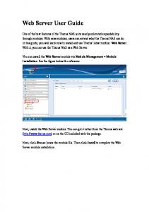
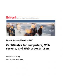


![My Devices User Guide - Cisco [PDF]](https://m.moam.info/img/260x300/my-devices-user-guide-cisco-pdf_647e0472098a9e7f638b45b0.jpg)
![Cisco TelePresence MediaP2 User Guide [PDF]](https://m.moam.info/img/260x300/cisco-telepresence-mediap2-user-guide-pdf_648802df098a9e75038b45ae.jpg)


