8th Annual Conference on Systems Engineering Research March 17th - 19th 2010, Hoboken, New Jersey, United States Paper # 1569268581
Clarifying the Concepts of System Maturity, System Readiness and Capability Readiness through Case Studies Mr. Abideen Tetlay FIAP
Prof. Philip John FREng
Dept. of Systems Engineering & Human Factors School of Engineering Cranfield University (UK) Cranfield, Bedfordshire, MK43 0AL E-mail:
[email protected]
Dept. of Systems Engineering & Human Factors School of Engineering Cranfield University (UK) Cranfield, Bedfordshire, MK43 0AL E-mail:
[email protected]
Copyright © Mr. Abideen Tetlay and Prof. Philip John, Cranfield University (UK) 2010. Published and used by CSER 2010 with permission.
Abstract This paper clarifies the key concepts of System Maturity, System Readiness and Capability Readiness and refines their definitions. The authors have achieved this by analysing three high-profile defence projects as case studies. The following military based systems were chosen: Chinook Helicopter; Apache Helicopter; and the Type 45 Anti-Air Warfare Destroyer. Keywords: System Maturity, System Readiness, Operational Capability, Capability Readiness
Introduction Systems are becoming increasingly complex due to the need to integrate with other systems to form systems of systems and networked systems of systems. Many systems are also software driven rather than mechanical driven adding to the level of complexity. You could therefore argue that it is not unsurprising that many systems, whether new or existing, still continue to cause unexpected and unacceptable behaviour even though they were considered to be “ready” for use. Clearly, we are not proficient enough at understanding how systems should behave in the real world context and the „capability‟ expected of them. We need to be able to assess and measure, with confidence, a System‟s Maturity and Readiness within a development programme and overall lifecycle. We need to have confidence in the use of existing „maturity‟ assessments and Readiness Levels as a systems engineering and project management tool to capture evidence and assess, measure and communicate
a System‟s Maturity and Readiness in a reliable and consistent manner to stakeholders. The aim of this study is to clarify and refine the notions of „maturity‟ and „readiness‟ through case study analysis. This paper is structured as follows. First, we describe the methodology used for this study and provide a short précis of the chosen case studies. Then, we clarify and refine the notions of „maturity‟ and „readiness‟ using the evidence found from the case studies. Finally, conclusions are drawn and the next stages of our research are provided in terms of recommendations for further research.
Methodology The methodology used for this study was Case Studies. We selected this particular approach to challenge theoretical work previously undertaken by (Tetlay and John 2009a,b,c); to allow for the in-depth exploration of solutions for complex issues identified by (Tetlay and John 2009a,b,c) within its real-life context, especially when the boundaries between phenomenon and context are not clearly evident (Yin 2009); and benefits from the prior development of theoretical propositions by (Tetlay and John 2009a,b,c) to guide data collection and analysis (Yin 2009). We chose multiple case studies to allow us to make analytic generalisation and not for statistical generalisation (Robson 2002). We hand-picked the following three case studies: Chinook Helicopter; Apache Helicopter; and the Type 45 Anti-Air Warfare Destroyer. We specifically identified these case studies as being relevant to our research, because we wanted to examine both new and existing defence systems spanning a significant length of time (50-60 years) Page 1 of 10
developed by multiple defence contractors and subcontractors across the US, UK and Europe. We specifically selected defence systems, because we are not looking at “maturity” or “capability” from a CMMISM (CMMISM 2008) process perspective as explained by (Tetlay and John 2009a,b,c), i.e. the process maturity of the capability, but in terms of the Operational Capability of the system or product, similar to the way the UK MoD looks at capability from a military operational capability perspective (MoD 2008c,d). We now give the reader a synopsis of each of the three case studies as a way of providing background information about these high-profile military defence systems: Chinook Helicopter - The CH-47 Chinook Helicopter is a twin-engine, tandem rotor helicopter designed for transportation of cargo, troops and weapons, during day, night, visual and instrument conditions. Development of the medium lift Boeing Vertol (models 114 and 414) CH-47 Series Chinook began in 1956. Since then the effectiveness of the Chinook has been continually upgraded by successive product improvements: the CH-47A; CH-47B; CH47C; and CH-47D. The amount of load a cargo helicopter can carry depends on the model, the fuel on board, the distance to be flown and atmospheric conditions (NAO 2008; FAS 2008; FAS 1999; Boeing 2008a,b; FAS 1997). Apache Helicopter - The Apache Helicopter is a twin-engine army attack helicopter developed by McDonnell Douglas (now Boeing). It entered service with the US Army in 1984 and has been exported to Egypt, Greece, Israel, the Netherlands, Japan, Saudi Arabia, United Arab Emirates (UAE) and the UK. The US Army has more than 800 Apaches in service and more than 1,000 have been exported. A consortium of GKN Westland (now AgustaWestland), Boeing, Lockheed Martin, Northrop Grumman and Shorts bid a version of the Longbow Apache for the UK Army attack helicopter requirement which was selected in July 1995. The first helicopter entered service in January 2001 designated as the Apache AH Mk1. The UK Apache is fitted with RTM322 engines from RollsRoyce / Turbomeca (Net Resources International 2009a; NAO 2002; Overkleeft 1996; Bond 1990; Slade 2008; USGAO 2001). Type 45 Anti-Air Warfare Destroyer – The UK Royal Navy's Type 45 destroyers are to replace the Type 42 destroyers, in service since 1978. Six Type 45 destroyers have been contracted. The destroyers are to enter service by 2014. A full-scale engineering development and initial production (FSED/IP) contract has been placed on BAE Systems Marine as project prime contractor (NAO 2009a,b; Net Resources International 2009b; Scott 2006; Downs 2007).
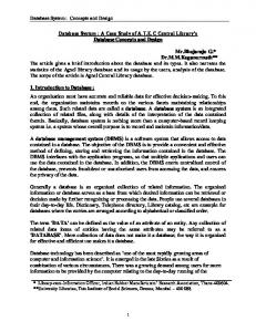
System Maturity We showed that there is not a sufficiently clear distinction between System Maturity and System Readiness. Current definitions of Readiness Levels seem to assess System Maturity in order to determine System Readiness and they all refer to the key term of „maturity‟ in their definitions. Based on this evidence, you could infer that the notion of „maturity‟ is encapsulated within the notion of „readiness‟ and they appear to be used interchangeably. It could also be argued that the existing Readiness Levels actually provide a „maturity‟ metric as opposed to a „readiness‟ metric. This is likely to lead to the confusion in the understanding of the terms of „maturity‟, i.e. System Maturity and „readiness‟, i.e. System Readiness in systems engineering and in the use of existing Readiness Levels (Tetlay and John 2009c). To address these issues, we suggested that clarification is required for the terms of System Maturity and System Readiness, because the potential use of these terms is very important. They are directly linked to Risk, Progress and Fitness for Purpose. The success of systems and system projects would benefit from a more meaningful and appropriate use of these concepts (Tetlay and John 2009c). One of the most recognised and frequently used existing Readiness Levels is NASA‟s Technology Readiness Levels (TRLs) as illustrated in Figure 1. However, according to (Sauser et al., 2006) “TRL is not an end state to determining a system‟s readiness. TRL is only a measure of an individual technology and not systems readiness. There is no proven, tested, systematic index of systems readiness” (Sauser et al., 2006). In fact, if you look carefully at the TRLs, you will notice that from TRL1 through to TRL8 they are all focusing on the design, development and testing aspect of the System Development and overall Lifecycle. Although, we would argue that both TRL4 and TRL5 are to do with verification and not validation of the subsystem as highlighted in yellow in Figure 1. Also, note that only TRL9 is focusing on the „operational‟ aspects of the system or product as highlighted in green in Figure 1. Based on this evidence, we have therefore used the System Development and overall Lifecycle “V-Model” to map a new set of System Maturity Levels across the system development part of the system engineering lifecycle as shown in Figure 2. The left hand-side of the model focuses on the „Design Maturity‟ (consistency, completeness, coherence and confidence) for the system or product being engineered and the right hand-side concentrates on achieving verification, i.e. System Maturity. The purpose of the System Maturity Levels is to determine where you are in the System Development Lifecycle which determines the degree of Page 2 of 10
System Maturity for the system or product currently being developed. The left hand-side of the System Development Lifecycle is less „mature‟ than the right hand-side. Obviously, the further you are in the System Development Lifecycle, moving from the left to the right hand-side, the closer you are towards achieving a physical system or product and therefore achieving System Maturity.
Figure 1: NASA Technology Readiness Levels (TRLs)
In order to help clarify the notions of “maturity” (System Maturity) and “readiness” (System Readiness), we advocated that these terms and notions should be treated as two clear and distinct entities both of which are actually addressing two completely different questions within the System Development and overall Lifecycle. To illustrate this argument, we mapped System Maturity and System Readiness against the System Development and overall Lifecycle as depicted in Figure 2. We also provided definitions for both System Maturity and System Readiness (Tetlay and John 2009c).
Figure 2: System Maturity Levels
The new revised definition for System Maturity which takes into account the new System Maturity Levels is provided below.
System Maturity is the verification within an iterative process of the System Development Lifecycle and occurs before System Readiness, i.e. the system or product must first be fully „mature‟ before it can be “ready” for use. The process starts from System Requirements and finishes at System Verification. System Maturity asks the question: Do we have a complete, well defined design that has been implemented and verified, i.e. we have decided what we want to implement and we have achieved this; the designed system or product now physically exists (the long horizontal dotted-line between User Requirements and System Requirements in Figure 2 denotes the physical existence of the produced-engineered system or product and also separates System Maturity from System Readiness)? System Maturity is both solution dependent and context specific. The System Requirements implicitly determines the context of use. System Maturity is only concerned with the intrinsic aspects of the system or product, i.e. the system or product features. Three phases or states of “System Maturity‟ could be envisaged: (1) System is Immature (SI) - In the System Requirements stage of the System Development Lifecycle or just completed it. System Maturity Level is equal to 0; (2) System Maturity is in Progress (SMP) - Working your way through the System Development Lifecycle (for example, the design, development and testing part of the System Development Lifecycle) in order to decide and define the system design and bring it into physical existence. This covers System Maturity Levels 1 to 5, inclusive; and (3) System Maturity has been Achieved (SMA) - The design, development and testing of the system or product is now complete, fully “mature” and tested and now physically exists. To achieve System Maturity the system or product must be verified against the System Requirements, i.e. you have achieved System Maturity by building the system right based on „Best Practice‟ procedures and „Standards‟ in place. This can only occur if all the Aspects of System Maturity (AoSM) are in place, i.e. the stages of the System Development Lifecycle (see Figure 4). System Maturity Level is equal to 6. Verification confirms that the system element meets the design-to or build-to specifications. It answers the question “Did you build it right? (CMMISM 2008)”. We now provide some examples of System Maturity to further explain and clarify this important concept. The following are all examples of systems or products failing to achieve System Maturity, because they have failed to build the systems or products based on „best practice‟ procedures and/or „standards‟ in place. They also illustrate the importance of first Page 3 of 10
achieving System Maturity before you can achieve System Readiness, i.e. before the system or product can even be considered to be “ready” for use which is the „Fitness for Purpose‟ question: “The Chinook Mk3 helicopters have not flown on operations because the Department refused to grant the helicopters an airworthiness certificate. Although Boeing met its contractual obligations, the avionics software fell short of United Kingdom military airworthiness standards and the helicopters have not flown on operations” (NAO 2008); “By the time the airworthiness issues with the Chinook Mk3 helicopters became apparent, emerging legislation and operational requirements meant that the helicopters would need to be modified before they could be deployed on operations” (NAO 2008); “The Reversion project aims to deliver the eight Chinook Mk3 helicopters to a standard such that they can be deployable to Afghanistan in 2009-10” (NAO 2008); “The US Secretary of State requires all aircraft, associated equipment and software to be designed, constructed, maintained and operated in such a manner that they are airworthy” (NAO 2008); and “There is still some risk to the delivery of the Apache as development work to install a range of more recently contracted enhancements to the baseline helicopter has yet to be completed” (NAO 2002). The examples below demonstrate System Maturity as being solution dependent: “In September 2004 the Department decided to explore further a “Fix to Field” solution which involved the replacement or modification of the cockpit display systems, the communications systems and fuel quantity gauging, together with the integration of special operations equipment and a comprehensive Defensive Aids Suite” (NAO 2008); and “Each confirmed that the solution was technically feasible, had a sound approach to airworthiness and would enable the Chinook Mk3 to be declared an operationally effective helicopter to be used on special operations” (NAO 2008). The following example shows that System Maturity is only concerned with the intrinsic aspects of the system or product, i.e. the system or product features: “Three Chinook airframes, CH-47A, CH-47B, and a CH-47C, were stripped down to their basic airframes and then rebuilt with improved systems to provide three CH-47D prototypes. Improvements included upgraded power plants, rotor transmissions, integral lubrication and cooling for the transmission systems, and fiberglass rotor blades. Other improvements included a redesigned cockpit to reduce pilot workload, redundant and improved electrical systems, modularized hydraulic systems, an advanced flight control system, and improved avionics” (FAS 2008).
In order to achieve System Maturity a system or product must be verified against the System Requirements. The following are examples of System Requirements: “The fuel cells must be crash-worthy and self sealing up to 50 caliber hits” (FAS 2008); and “Type 45 shall carry a Medium Calibre Gun System of at least 114mm” (NAO 2009a,b). The following is an example of Design which is Immature leading to increased risk and uncertainty: “The Department and its commercial partners were over-optimistic in their predictions of the time and resources required to procure the first six ships, and did not establish the project on a suitable basis given the levels of risk and uncertainty and the immaturity of the design of the ships and the PAAMS missile system” (NAO 2009a,b). However, the following is an example of Design which is Mature. Note that the design is able to cope with new requirements, including Urgent Operational Requirements (UOR) and requirements which have yet to be determined: “The Type 45 could also accommodate cruise missiles such as the Tomahawk and anti-ballistic missiles if a requirement was identified in future” (Net Resources International 2009b).
System Readiness We highlighted a number of issues with existing Readiness Levels and one of the issues is that existing Readiness Levels seem to assess System Maturity in order to determine System Readiness and they all refer to the key term of „maturity‟ in their definitions (Tetlay and John 2009c). We also suggested that existing Readiness Levels actually provide a „maturity‟ metric as opposed to a „readiness‟ metric. This is likely to lead to the confusion in the understanding of these terms and in their practical use (Tetlay and John 2009c). We will use System Readiness Levels (SRLs) (MoD 2008a,b) which are depicted in Figure 3 to further illustrate this issue. The following text defines SRLs (MoD 2008a,b) and is also shown in Figure 3: “System Readiness Levels (SRLs) have been developed as a project management tool to capture evidence, and assess and communicate System Maturity in a consistent manner to stakeholders. SRLs define a set of nine maturity steps from Concept to in-service across a set of systems engineering disciplines” (MoD 2008a,b). We can clearly see that the intention is to assess System Maturity and not System Readiness despite the fact that these are System Readiness Levels and not System Maturity Levels. In the example shown in Figure 3, the Project is at SRL3 or do they really mean the Project is at SML 3, i.e. System Maturity Level 3?
Page 4 of 10
Figure 3: System Readiness Levels (SRLs)
The new revised definition for System Readiness which takes into account the findings from the case study analysis is provided below. System Readiness is the validation aspect of the system development and overall lifecycle and occurs after System Maturity, i.e. the system or product must first be fully „mature‟ before it can be made “ready” for use. The process starts from User Requirements and finishes at System Validation. System Readiness determines whether or not the system or product is now “ready” for use in its intended operational environment. System Readiness is a relative metric based on context and use, i.e. the „Fitness for Purpose‟ question. System Readiness is context dependent. The User Requirements explicitly determine the context of use. System Readiness is solution independent, i.e. users do not care about the solution, only whether or not the system or product is “ready” for use. System Readiness is only concerned with the extrinsic aspects of the system or product, i.e. is the system or product now “ready” to be used in the real-world context? System Readiness is dependent on Enablers and Barriers. Measures of Effectiveness (MoE) can be used to assess and measure the system‟s or product‟s effectiveness. To achieve System Readiness the system or product must be validated against the User Requirements, i.e. you will achieve System Readiness by building the right system or product for a given context. Three phases or states of “System Readiness‟ could be envisaged: (1) No System Readiness (NSR) – Certain enablers for the system or product for a particular context are not currently in place and certain barriers are also preventing the system or product from being operational and “ready” for use; conceptually, this can be thought of as System Readiness being equal to 0; (2) Initial System Readiness (ISR) - Certain enablers for the system or product for a particular context are currently in place, but certain barriers are preventing the system or product from being fully operational and
therefore the system or product only has limited operational use for a particular context, but is “ready” for use for that context only; conceptually, this can be thought of as System Readiness being equal to 1; and (3) Full System Readiness (FSR) – All the enablers for the system or product for a particular context are currently in place and none of the current barriers are preventing the system or product from being fully operational and the system or product has full operational use for a particular context and is “ready” for use for that context only; conceptually, this can be thought of as System Readiness being equal to 2. Validation answers the question of “Did you build the right thing? (CMMISM 2008)”. Note that this question is implicitly context dependent, i.e. „right for what‟?
Figure 4: System Readiness Model
We have created a conceptual model entitled, “System Readiness Model” as depicted in Figure 4 to try and capture the notion of „maturity‟ (System Maturity) and „readiness‟ (System Readiness). As you can see in Figure 4, we have taken the system development stages of the System Development and overall Lifecycle and labelled these as Aspects of System Maturity (AoSM) which need to be in place to achieve System Maturity and we have labelled the left hand-side of the System Maturity part of the model as „Design Maturity‟ and the right hand-side as „System Maturity‟. Sitting above System Maturity is System Readiness showing all the component parts of System Readiness. In order to determine System Readiness of a system or product that depends on whether or not the system or product can be „validated‟ against the User Requirements and is dependent on the Enablers and Barriers as well as the context of use. Measures of Effectiveness (MoE) could be used to assess and measure the degree of System Effectiveness (Verma et al., 2003).
Page 5 of 10
We now provide some examples of System Readiness to further explain and clarify this important concept. The following are all examples of System Readiness, because they are concerned with how the system or product is likely to behave in its intended operational environment for a given context: “...speed for any mission will vary greatly depending on load configuration (internal or external), time of day, or weather conditions” (FAS 2008); “The amount of load a cargo helicopter can carry depends on the model, the fuel on board, the distance to be flown, and atmospheric conditions” (FAS 2008); “The Chinook's primary mission is moving artillery, ammunition, personnel, and supplies on the battlefield. It also performs rescue, aeromedical, parachuting, aircraft recovery and special operations missions” (FAS 2008); “Chinooks (CH47D) can fly more than 150 mph at full load more than 330 nautical miles with longrange fuel tanks. With a crew of three, the CH47s can transport 44 seated troops or 24 casualty litters” (Boeing 2008a,b); and “Daring will be able to transit 7,000 n miles at a speed of 18 kt and reach a maximum speed of more than 27 kt” (NAO 2002). The following are examples of System Readiness, but in particular, Initial System Readiness (ISR) due to certain Enablers and/or certain Barriers in existence: “The helicopters can fly but are restricted to flying on cloudless days above 500 feet where the pilot can navigate via landmarks” (NAO 2008); “...the limitation aspects of operating the aircraft that are applicable to the aircraft systems, rather than flying the aircraft. Thus it covers items such as: Engine, Fuel System, Electrical System, Autopilot, Communications, and Radar” (NAO 2008); “Without their primary weapons systems these Type 42s could not be deployed in an air defence role”. (NAO 2009a,b); and “...the Army determined that aircraft (Chinook CH-47D) with certain gear and bearing assemblies can continue training and perform operational missions that are limited to 80 percent, dual-engine torque” (FAS 1999). The following example illustrates the importance of User Requirements in achieving System Readiness, i.e. in order to achieve System Readiness a system or product needs to be validated against the User Requirements: “When it is in service, each Type 45 destroyer should have met all of its key user requirements” (NAO 2009a,b); and “On current plans, Daring, the first of class will enter service in December 2009, when it will meet all its defined Key User Requirements... (NAO 2009a,b). The following is an example of a User Requirement:
“Type 45 shall be able to provide close tactical control to at least four, fixed wing or groups of, aircraft” (NAO 2009a,b). The following is an excellent example of where a system or product has achieved System Readiness, but not necessarily Capability Readiness which we will discuss in the next section: “On current plans, Daring, the first of class will enter service in December 2009, when it will meet all its defined Key User Requirements. There are, however, a number of risks both to achieving these dates and to delivering the full capability in the longer term. In the short term these include integrating the destroyer and PAAMS; and trialling and operating the Combat Management System” (NAO 2009a,b).
Capability Readiness Many systems, whether new or existing, still continue to cause unexpected and unacceptable behaviour even though they were considered to be “ready” for use. Clearly, we are not proficient enough at understanding how systems should behave in the real world context and the „capability‟ expected of them. It is important to note that we are not looking at „capability‟ from a CMMISM (CMMISM 2008) process perspective as explained in (Tetlay and John 2009a,b,c), i.e. the maturity of the capability, but in terms of the Operational Capability of the system or product, similar to the way the UK MoD looks at capability from a military operational capability perspective (MoD 2008c,d). We suggested that just because a system or product is now considered to be “ready” for use in its intended operational environment, does not necessarily mean that the system‟s or product‟s „capability‟ is also ready. Therefore, the concept of “Readiness”, i.e. System Readiness may be further expanded and related to „capability‟, i.e. Capability Readiness (Tetlay and John 2009a,b,c). We first coined the term “Capability Readiness” in (Tetlay and John 2009c) and then extended the definition in (Tetlay and John 2009a,b). We mapped „Capability Requirements‟ at the very beginning of the V-Model as illustrated in Figure 2 and before User Requirements which has traditionally been the starting point of the model. The premise for this is to ensure that we capture the full “complete” requirements starting from and including the „Capability Requirements‟ which we need to build and factor into the System Development and overall Lifecycle (Tetlay and John 2009c). The new revised definition for Capability Readiness which takes into account the findings from the case study analysis is provided below.
Page 6 of 10
Capability Readiness determines whether or not the „total-wider system or product‟, including Systems of Systems (SoS) and Networked Systems of Systems, for example, Networked Enabled Capability (NEC) has the ability and the capacity to completely fulfil the operational capability of the system or product for a given context in its intended operational environment, within the scope of the Capability Requirements and its aims and objectives. Once we know that the system or product has achieved System Readiness then we can raise the Capability Readiness question. Like System Readiness, Capability Readiness is also looking at the validation of the system or product and is also context dependent. The process starts at Capability Requirements and finishes at Capability Validation. The Capability Requirements explicitly determine the context of use. To achieve Capability Readiness the system or product must be validated against the Capability Requirements, i.e. you will achieve Capability Readiness if you can “demonstrate” that the system or product does have the ability and the capacity to completely fulfil the operational capability of the system or product for its intended operational environment as prescribed by the Capability Requirements. Capability Readiness is a relative metric based on context and use, i.e. the „Fitness for Purpose‟ question. Capability Readiness is solution independent, i.e. users do not care about the solution, only whether or not the system‟s or product‟s capability is “ready” for use. Capability Readiness is only concerned with the extrinsic aspects of the system or product, i.e. is the system‟s or product‟s capability now “ready” to be used in the real-world context? Capability Readiness is dependent on Enablers and Barriers. Measures of Effectiveness (MoE) can be used to assess and measure the system‟s or product‟s operational capability effectiveness. Capability therefore translates to the system‟s or product‟s “Ability” (actual/physical behaviour) and “Capacity” (assumed/predicted „potential‟ behaviour) to achieve a need as depicted in Figure 5. In terms of the assessment and measurement of Capability Readiness, this consists of three things: the „assumed‟ (based on assumptions, conjecture and anecdotal evidence), „predicted‟ (based on historical evidence; development of a prototype/simulation for example) and „actual‟ (based on current, physical/real-life and real-time) result of the behavioural aspects of a system or product using both qualitative (non-formal methods) and quantitative (formal methods) techniques (Tetlay and John 2009a,b). When looking at Capability Readiness, it is important to recognize the „total-wider system or product‟ and to distinguish this from the „producedengineered system or product‟ which is composed of conventional development as illustrated in Figure 2 above (Tetlay and John 2009a,b,c).
Figure 5: Capability Readiness Definition
This is a key distinction between „Capability Readiness‟ and „System Readiness‟. System Readiness is only concerned with the „produced-engineered system or product‟, whereas Capability Readiness is concerned with the „total-wider system or product‟ (the long horizontal dotted-line at the very top of the diagram in Figure 2 above between Capability Requirements and User Requirements separates and distinguishes System Readiness from Capability Readiness) (Tetlay and John 2009a,b,c). Three phases or states of “Capability Readiness‟ could be envisaged: (1) No Capability Readiness (NCR) – Certain enablers for the system or product for a particular context are not currently in place and certain barriers are also preventing the system‟s or product‟s capability from being operational and “ready” for use; conceptually, this can be thought of as Capability Readiness being equal to 0; (2) Initial Capability Readiness (ICR) - Certain enablers for the system or product for a particular context are currently in place, but not all of them and certain barriers are preventing the system‟s or product‟s capability from being fully operational and therefore the system or product only has limited operational capability for a particular context, but is “ready” for use for that context only; conceptually, this can be thought of as Capability Readiness being equal to 1; and (3) Full Capability Readiness (FCR) – All the enablers for the system or product for a particular context are currently in place and none of the current barriers are preventing the system‟s or product‟s capability from being fully operational and the system or product has full operational capability for a particular context and is “ready” for use for that context only; conceptually, this can be thought of as Capability Readiness being equal to 2.
Page 7 of 10
We have created a conceptual model entitled, “Capability Readiness Model” as depicted in Figure 6 to try and capture the notion of „capability‟ (Capability Readiness). As you can see in Figure 6, we have taken the Defence Lines of Development (DLoD) (MoD 2008c,d) as a basis of our model. All the DLoD need to be in place to achieve Operational Capability, but in order to determine the Capability Readiness of a system or product that depends on whether or not the system or product can be „validated‟ against the Capability Requirements and is dependent on the Enablers and Barriers as well as the context of use. Measures of Effectiveness (MoE) could be used to assess and measure the degree of Operational Capability (Verma et al., 2003).
Figure 6: Capability Readiness Model
We now provide some examples of Capability Readiness to further explain and clarify this important concept. The following are all examples of Capability Readiness, because they are concerned with how the system‟s or product‟s capability is likely to behave in their intended operational environment for a given context: “Assuming an appropriate level of pilots and logistic support, additional Chinook flying hours could have been used to carry out operations with greater flexibility including more non-essential military tasks in support of the international mission in Afghanistan” (NAO 2008); “Past experiences of operating in a desert environment have resulted in restricted operations and reduced engine life”. (FAS 1997); and “The new Type 45 Carriers and its aircraft are planned to be capable of operating in all weathers, day and night, flying strike missions, conducting offensive support for ground forces ashore and where necessary, providing force protection to the fleet. The Aircraft Carrier will also be capable of supporting the operation of helicopters in a wide variety of roles including land attack and ground support” (NAO 2009a,b).
The following examples focus on the DLoD and their importance in providing operational capability: “...risks remain to be overcome on a number of Lines of Development before the Apache can be successfully introduced into service” (NAO 2002); “...the infrastructure should be in place for delivery of the initial capability” (NAO 2002); “...the delivery of Apache training has been delayed which has in turn delayed introduction of the capability” (NAO 2002); “The Department is bringing in the capability taking into account the Defence Lines of Development. This approach aims to ensure that all elements of the capability such as the necessary training and infrastructure, not just the ships themselves, are introduced coherently” (NAO 2009a,b); and “There are, however, some issues with the first four of the Defence Lines of Development that may limit the deployable capability if the Department‟s mitigating actions are not successful” (NAO 2009a,b). The following are examples of Capability Readiness, but in particular, Initial Capability Readiness (ICR) due to lack of certain Enablers and current Barriers preventing full operational capability: “The hot mountainous conditions of Vietnam limited the Ch-47A models performance capabilities and generated a requirement for increased payload and better performance” (FAS 2008); “Clearance of the aircraft to operate in conditions of ice is targeted for December 2006” (NAO 2002); “...clearance for the Apache to operate in conditions of snow is planned for August 2003 and to operate in ice conditions is targeted for December 2006. This timescale means there will initially be some restrictions on the environments in which the aircraft can operate when it is introduced into service in 2004” (NAO 2002); “Because of the limited capability of other equipment the Apache will not, however, have the capacity for secure voice communications with the United Kingdom's Gazelle, Lynx, Sea King Mark 4 and Puma helicopters, nor will it be able to exchange data securely with most of the United Kingdom's military aircraft or the other battlefield helicopters or with United Kingdom ground forces” (NAO 2002); “Apache and Merlin Helicopters were deployed on operations before reaching full operating capability. Both have proved to be successful on those operations, Apache in Afghanistan, and the RAF version of Merlin in Iraq” (Slade 2008); “The delays on the Type 45 destroyer project mean that the Department is still actively operating five Type 42 destroyers which offer a much more limited capability” (NAO 2009a,b); and “...several pieces of equipment will be fitted to the destroyers incrementally after they come into service meaning that the full capability will not be available until the middle of the next decade” (NAO 2009a,b).
Page 8 of 10
The following example is of Capability Readiness, but in particular, Full Capability Readiness (FCR): “The full capability - a true integrated and joint capability that would allow the Apache to be based and supported at sea with an Amphibious Task Force for extended periods and in more demanding sea conditions - remains the final objective” (NAO 2002). The following example illustrates the importance of Capability Requirements in achieving Capability Readiness, i.e. in order to achieve Capability Readiness a system or product needs to be validated against the Capability Requirements: “Deliver agreed capability against approved requirements” (NAO 2002). The following are examples of Capability Requirements: “The Department is aiming to deliver at this point a capability that will allow the Apache to be re-fuelled and re-armed at sea and then fly to operations on land” (NAO 2002); “...escort, ground suppression and armoured reconnaissance. ...operate from ships of the Royal Navy and Royal Fleet Auxiliary” (Slade 2008); and “...be able to operate Lynx, Merlin and Chinook helicopters. ...to operate in a hostile environment, either to provide a protective umbrella over a force of landing ships, an aircraft carrier or a group of merchant ships, or to conduct a wide range of other tasks such as maintaining a United Kingdom presence, embargoes or supporting forces ashore” (NAO 2009a,b).
Conclusions This study clarifies the concept and notion of System Maturity, System Readiness and Capability Readiness, including refinement of their definitions based on the evidence obtained from the following three high-profile defence projects as Case Studies: Chinook Helicopter; Apache Helicopter; and the Type 45 Anti-Air Warfare Destroyer. This study also introduced a new set of System Maturity Levels and a conceptual model for System Readiness and Capability Readiness.
Further Research Further research is required to put the „theory‟ into „practice‟. We aim to do this in two stages: first, to create a theoretical conceptual Framework based on the results obtained from the case study analysis and from our previous research and secondly, to apply and test the Framework against a real world system engineering project and then refine the Framework, as appropriate, for wider use and applicability. This is part of our ongoing research.
Acknowledgements The authors would like to thank the UK Engineering and Physical Sciences Research Council (EPSRC) and BAE Systems for jointly funding the research project.
References CMMISM for Systems Engineering/Software Engineering (November 2008), Version 1.02 (CMMI-SE/SW, V1.02), Software Engineering Institute, Carnegie Mellon University, available at: http://www.sei.cmu.edu/reports/00tr018.pdf (accessed 10th October 2009) Boeing (2008), CH-47D Chinook Helicopter Backgrounder, available at: http://www.boeing.com/rotorcraft/military/ch47d/docs/CH47D_overview.pdf (accessed 7th September 2009) Boeing (2008), U.S. Army Special Operations Command Boeing MH47G Special Operations Chinook Backgrounder, available at: http://www.boeing.com/rotorcraft/military/ch47d/docs/MH47G_overview.pdf (accessed 7th September 2009) Bond, D. F. (1990), “Apache Readiness Problems Emerge As Threat to Longbow Development”, Aviation Week and Space Technology, Vol. 133, Issue 19, 29th October 1990, p. 79 Downs, D. S. (2007), Type 45: Design for Supportability, RINA, The Royal Institution of Naval Architects International Conference Warship 2007: The Affordable Warship, June 2007, Bath, UK, p. 23-32 Federation of American Scientists (1997), Operational Requirements Document for the Improved Cargo Helicopter (CH-47D Service Life Extension Program (SLEP)), available at: http://www.fas.org/man/dod-101/sys/ac/docs/ord_ich_jul97.htm (accessed 7th September 2009) Federation of American Scientists (1999), Army returns some Chinooks to flight, available at: http://www.fas.org/man/dod101/sys/ac/docs/a19990827chinback.htm (accessed 7th September 2009) Federation of American Scientists (2008), CH-47 Chinook, available at: http://www.fas.org/programs/ssp/man/uswpns/air/rotary/ch47chi nook.html (accessed 7th September 2009) MoD (2008), System Readiness Levels (SRLs), AOF Technology Management Policy, Information and Guidance on the Technology Management aspects of UK MOD Defence Acquisition version 1.0.1, available at: http://www.aof.mod.uk/aofcontent/tactical/techman/content/srl_ whatarethey.htm (accessed 29th November 2008) MoD (2008), System Readiness Levels (SRLs), AOF Technology Management Policy, Information and Guidance on the Technology Management aspects of UK MOD Defence Acquisition version 1.0.1, available at: http://www.aof.mod.uk/aofcontent/tactical/techman/content/srl_ applying.htm (accessed 29th November 2008) MoD (2008), What is Through Life Capability Management? Acquisition Operating Framework (AOF), The high level principles and information that guide how the UK MOD Defence Acquisition Community work version 2.0.6, available at: http://www.aof.mod.uk/aofcontent/operational/business/capabili tymanagement/capabilitymanagement_whatis.htm (accessed 10th October 2009) MoD (2008), Defence Lines of Development, Acquisition Operating Framework (AOF), The high level principles and information that guide how the UK MOD Defence Acquisition Community works version 2.0.8, available at: http://aof.mod.uk/aofcontent/strategic/guide/sg_dlod.htm (accessed 10th October 2009)
Page 9 of 10
National Audit Office (NAO) (2002), Building an Air Manoeuvre Capability: The Introduction of the Apache Helicopter, Report by the Comptroller and Auditor General, HC 1246, Session 2001-2002, London, UK National Audit Office (NAO) (2008), Ministry of Defence Chinook Mk3 Helicopters, Report by the Comptroller and Auditor General, HC 512, Session 2007-2008, London, UK National Audit Office (NAO) (2009), Ministry of Defence Providing Anti-Air Warfare Capability: the Type 45 Destroyer, Report by the Comptroller and Auditor General, HC 295, Session 20082009, London, UK National Audit Office (NAO) (2009), Providing Anti-Air Warfare Capability: the Type 45 Destroyer, National Audit Office Value for Money Report, HC 295 2008-2009, ISBN: 9780102954685 http://www.nao.org.uk/publications/0809/the_type_45_destroye r.aspx (accessed 24th September 2009) Net Resources International (2009), AH-64A/D Apache Attack Helicopter, USA, available at: http://www.armytechnology.com/projects/apache/ (accessed 10th October 2009) Net Resources International (2009), Type 45 Daring Class Anti-Air Warfare Destroyers, United Kingdom, available at: http://www.naval-technology.com/projects/horizon/ (accessed 27th September 2009) Overkleeft, W. J. (1996), TADS/PNVS – The Eyes of the Apache, Royal Aeronautical Society Conference, 23rd April 1996, Orlando, Florida, US, p. 6.1-6.9 Robson, C. (2002), Real World Research (2nd ed), Blackwell Publishing, MA, US Sauser B. et al., (2006), From TRL to SRL: The Concept of Systems Readiness Levels, Conference on Systems Engineering Research, Los Angeles, CA, US, April 7th – 8th 2006, available at: http://personal.stevens.edu/~bsauser/Publications_files/Sauser% 202006%20CSER.pdf (accessed 29th November 2008) Scott, R. (2006), “UK Royal Navy‟s Type 45 destroyer gets ready for launch milestone”, Jane’s International Defense Review, Vol. 39, p. 46-50 Slade, K. (2008), “Apache at 50,000 hours – airpower savagery untamed”, Defence Equipment and Support, Issue 02, June 2008, p. 18-19 Tetlay, A. and John, P. (2010), “Capability Readiness for ProductService Systems”, Proceedings of the Institution of Mechanical Engineers, Part B: Journal of Engineering Manufacture, 2010, ISSN:0953-4054 (Print); 2041-2975(Online) - Accepted Tetlay, A. and John, P. (2009), Capability Readiness for ProductService Systems, 7th International Conference on Manufacturing Research (ICMR09), September 8th – 10th 2009, Warwick University (UK) Tetlay, A. and John, P. (2009), Determining the Lines of System Maturity, System Readiness and Capability Readiness in the System Development Lifecycle, 7th Annual Conference on Systems Engineering Research (CSER09), April 20th – 23rd 2009, Loughborough University (UK), ISBN: 978-0-95624400-0 United States General Accounting Office (GAO) (2001), Defense Logistics: Information on Apache Helicopter Support and Readiness, report number GAO-01-630, Report to Congressional Committees Verma, D. et al., (2003), “System Training Metrics and Measures: A Key Operational Effectiveness Imperative”, Systems Engineering, Vol. 6, No. 4, p. 238-248 Yin, R. K. (2009), Case Study Research: Design and Methods (4th ed), SAGE Publications, California, US
Biographies Abideen Tetlay is a second year PhD Systems Engineering researcher in the School of Engineering at Cranfield University (UK). His doctorate is funded by the UK Engineering and Physical Sciences Research Council (EPSRC) and BAE Systems. He is also working as a Systems Engineer for Raytheon Systems Limited (UK) covering the Systems Engineering Lifecycle to primarily support a major new Command and Control (C2) programme for the UK Ministry of Defence (MoD). He has previously spent 10 years working as a professional Software and Database Engineer reaching Consultant level. He has worked for the following UK based companies: K3 Business Technology Group; Bidwells Property Consultants; Lloyds Banking Group; and the Royal Society of Chemistry. Before embarking on an IT career, he first obtained a Bachelor's degree BA (Hons) Business Administration from the University of Bedfordshire (UK). This was followed by a Master‟s degree MSc Information Technology (Management Information Systems) from Cranfield University (UK) and then he moved into the IT field. Several years later, he gained another Master‟s degree MSc Software Engineering from St Cross College, University of Oxford (UK) which was sponsored by Lloyds Banking Group. He is a Fellow of the Institution of Analysts and Programmers (FIAP).
Philip John joined Cranfield University (UK) in 1999 as the Professor of Systems Engineering and is the Head of the Department of Systems Engineering and Human Factors. Following his PhD at Imperial College, London he spent 18 years in industry, holding a wide range of systems engineering and management roles, including Head of Systems Engineering for a major multinational company. His experience and responsibilities in industry encompassed the whole scope of systems engineering, including Requirements Engineering, System Design, ILS, ARM, Human Factors, Safety, Systems Proving & Simulation and Modelling. He is a member of several National Advisory Committees and Industrial Steering Boards and served as the President of the International Council on Systems Engineering (INCOSE) in the UK from 2003 to 2004. In 2009 he was elected into the Fellowship of the Royal Academy of Engineering. The highest national award for engineers of its kind, the title is only bestowed on leading engineers within the field who have been elected by their peers to the Fellowship. His research interests include: Understanding Complex Systems and Systems of Systems (SoS); Managing Complex Systems Projects and Risks; Through Life Capability Management; and Coping with Uncertainty and Change in Systems.
Page 10 of 10