CLASSIFICATION OF EEG SIGNALS IN THE AMBIGUITY DOMAIN FOR BRAIN COMPUTER INTERFACE APPLICATIONS Gary Garcia, Touradj Ebrahimi and Jean-Marc Vesin Swiss Federal Institute of Technology - EPFL, CH-1015 Lausanne, Switzerland
[email protected],
[email protected],
[email protected] Abstract: Human-Computer Interaction research for motor impaired people has led to design of various Brain Computer Interfaces (BCI) based on the analysis of electroencephalographic signals (EEG). In this paper we propose a flexible and modular BCI system to allow subjects to interact with a computer based on EEG classification in the ambiguity domain. Keywords: Brain Computer Interface, Ambiguity Function, EEG, Human Computer Interface. 1. INTRODUCTION Automatic systems capable of understanding different facets of human communication will be at the heart of Human Computer Interfaces (HCI) in the near future. Nowadays, HCIs based on speech, facial and gesture recognition are the subject of intensive research [1]. In the case of motor impaired subjects, special HCIs have been designed based on pattern recognition in electroencephalographic (EEG) [2] or electromyographic (EMG) signals [3]. An HCI which uses the brain activity as communication support is called a Brain Computer Interface (BCI). If the brain activity is monitored with EEG we have an EEG-based BCI. In the sequel we will simply call BCI an EEG-based BCI. The non-invasive EEG signals used in current BCIs can be divided in three categories [4]: Event Related Potentials (ERP), Slow Cortical Potential Shifts (SCPS) and Spontaneous Signals (SS). In this paper we focus on the analysis of SS. The advantage of SS in BCI is that the communication is continuous rather than discrete (as in ERP-BCIs) and faster than with SCPS-BCIs 2. THE PROPOSED BCI SYSTEM This section presents the overall architecture of a BCI system which was designed at EPFL to carry out research and development in man-machine interfaces for multimedia applications. The system has been designed to be very modular and flexible, in order to exploit it in a large number of BCI applications. In a typical application of this system, the resulting EEG pattern of a specific brain activity is first learned by the computer in an initial training session. The training process is mutual as both the human subject and the computer learn how to produce and how to recognize a given EEG corresponding to a mental task. Real-time interaction between the subject and the computer is therefore an essential part of the system.
For reasons of efficiency, the BCI system has been designed to allow subjects to perform various experiments from simple to more sophisticated, namely: Visualization experiment (VIS): Where the user can see a visual representation of her/his EEG activity in real-time. In this experiment, particular features associated with EEG signals, such as the power values in the typical frequency bands (δ, θ. α. β), interelectrode coherences, and total power at a given electrode are mapped to a 3D virtual environment, and regularly updated. The objectives of this experiment are calibration and familiarization of the subject with the system. In this study, each session was preceded by a short VIS experiment. Training without feedback experiment (TNF): A set of visual and audio information (images and sounds) are presented to the subject. Such visual and audio cues will request the subject to perform a predefined mental task. Training with feedback experiment (TWF): The subject is asked to perform a mental task and a feedback is provided. The feedback is positive when the computer recognizes the mental activity and negative otherwise. This feedback is possible as a model of the mental task is calculated during a previous TNF session. This experiment allows for a simultaneous learning of the subject and the computer through training. Control experiment (COE): As the result of the previous experiments is a model of mental activity, the subject can start to control the system by producing the mental activities for which the system has been trained. In this experiment, visual or sound cues are no longer necessary. Multi-user simultaneous training experiment (MUT): This is a particular form of the TWF experiment. It consists in a multi-user game whose goal is to gain the control of an object by performing a mental task. This session was chosen because of its more stimulating effect when compared to a simple feedback. As said earlier, the above experiments required a carefully designed BCI system in terms of flexibility
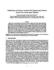
and speed, as a real-time processing of EEG signals is necessary. A solution fulfilling these requirements is a distributed system in which each component offers specific services to the others in an efficient and transparent way. Figure 1 depicts the general block diagram of our BCI system. EEG-data
Signal processing component
Signal production component
CORBA network Control signals
Rendering component
Figure 1. BCI-components overview. In this system, three types of components can be distinguished: 1- The signal production component whose responsibility is to digitize the recorded EEG signals and to transmit them to the processing units. 2- The signal processing component that is in charge of the signal pre-processing, feature extraction, model building and classification. 3- The rendering component which is used to display mental task cues for TNF and TWF, as well as the feedback for TWF. It also serves for rending in VIS, COE and MUT. The communication rules between these components were designed according to CORBA [5] specifications and implemented in JAVA, C and MATLAB. In this paper we report the results obtained from our experiments with VIS, TNF and TWF. 3. EXPERIMENTAL CONDITIONS AND PROTOCOLS Two male and healthy subjects (S1 and S2) aged 27 and 23 participated in five sessions of 20 minute long experiments. The VIS experiment was carried out during the first 10 minutes of every session. An initial mental model was then computed after the first session using TNF, while the following sessions were carried out with feedback (TFW). The EEG signals from subjects were recorded with reference to digitally linked ears [6] and from electrodes Fp1, Fp2, C3, C4, P3, P4, O1 and O2 of the 10/20 international system, at a rate of 256 Hz per channel. The subjects were asked to perform the following imagined mental tasks: Left arm movement (T1), Right
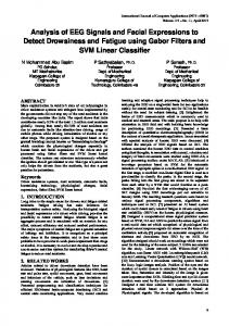
arm movement (T2) and an arithmetic task (T3) consisting in a multiplication between two 2-digit numbers. Our training protocol was designed in a way similar to that reported in [7]. The main reasons for such a choice were the good results reported, the need for a calibration and the necessity of a basis for comparison. The protocol of the TNF experiment is illustrated in the upper part of Fig. 2. At the beginning of the recording a warning image is displayed for three seconds, followed by a visual indication to perform a particular mental task (randomly chosen among T1, T2 and T3). This indication is displayed for one second on a computer screen. Six seconds later, another visual signal indicates the end of the trial and after a ten second break, this procedure is repeated. For the analysis of the EEG signals, only the last five seconds of each trial were used, in order to eliminate a possible evoked response to the visual indication requesting completion of a mental task. The protocol of the TWF is illustrated in the lower part of Fig. 2. At the end of each trial, a visual feedback is displayed. If the trial is correctly identified, an object moving to the left or to the right is displayed (in the case of motor tasks T1 and T2 respectively) or the correct result of the multiplication (in the case of arithmetic task T3). In case of wrong identification, a failure image is displayed. For each session, 30 trials were recorded resulting in 150 seconds of analyzed mental activity (50 seconds for each task). These signals were band-pass filtered between 0 and 40 Hz, and then divided in half-second segments (epochs). The epochs contaminated by eye blink artifacts [8] were rejected. These artifacts were detected by tracking the abrupt changes in amplitude at electrodes Fp1 and Fp2. An abrupt change was detected by comparing the current amplitude to the average of the last 128 samples; if this amplitude was larger than a “threshold” times the standard deviation of the precedent samples, the epoch was marked as contaminated by an eye artifact and thus rejected. The threshold was empirically set. For the analysis of results, the signals recorded at electrodes: C3, C4, P3, P4, O1 and O2 were examined. Therefore each epoch contained 6 channels of 128 samples. The mental task models were updated after each training session in order to provide an “updated feedback” in the next session.
Warning image
Visual cue
0
3
Break signal
Warning image
10
20
4
convolution product in Eq. 2. Therefore the kernel is designed in the ξ − τ (doppler-delay) domain, commonly called ambiguity domain. The 2-D function Φ (ξ ,τ ) can be seen as a mask in the ambiguity domain. In this paper, the goal of such a mask is to enhance the ξ − τ regions that better discriminate signals to be classified.
Training without feedback Warning image
Visual cue
Warning image
Feedback
Break 0
3
4
10
11
20
Training with feedback
Figure 2. TNF experiment protocol (top) and TWF experiment protocol (bottom). 4. CLASSIFICATION OF EEG SIGNALS IN THE AMBIGUITY DOMAIN Time-frequency representations of a signal can be divided in two groups according to the nature of their transformations: linear (Short-time Fourier Transform), and quadratic (based on the Wigner-Ville distribution). Here we focus on the quadratic representation. The cross Wigner-Ville distribution of two signals
x (t ) and y (t ) is defined as [9]. +∞
Wxy (t , f ) =
τ
τ
∫ y(t + 2 ) x *(t − 2 )e
− j 2π f τ
dτ
We chose a binary form for the discrete function Φ (k , n) . The points of Φ that are set to 1 are chosen to be those of maximum contrast between the classes. In this study, the signals coming from the following pairs of electrodes: C3-C4, P3-P4 and O1-O2, were used to compute three cross ambiguity functions per epoch. The use of lateral symmetric pairs was motivated by studies reporting efficient characterization of mental task based on inter-hemispheric correlations [6]. Optimization was performed separately on each pair. The classification procedure consisted in calculating the Mahalanobis distance in the ambiguity domain at a given number of points of maximum Fisher contrast, and to choose the most likely class to the epoch under analysis.
(1)
The Fisher contrast is defined as:
−∞
It can be shown that all cross time-frequency representations which are time-frequency covariant can be written as:
Cxyφ (t , f ) = ∫∫ φ ( s − t , v − f )Wxy ( s, v)dsdv
It can be shown that the convolution product (2) is equivalent to:
Cxy (t , f ) = ∫∫ Φ(ξ ,τ )Axy (ξ ,τ )e
j 2π ( tξ − f τ )
d ξ dτ
(3)
where Φ (ξ ,τ ) is the 2-D Fourier transform of φ ( s, v) and Axy (ξ ,τ ) is the cross-ambiguity function of
Axy (ξ ,τ ) =
τ
τ
∫ y(t + 2 ) x *(t − 2 )e
=
ξ
ξ
∫ Y *( f + 2 ) X ( f − 2 )e
− j 2πξτ
Ak (ξ ,τ ) − j Ai (ξ ,τ )
∑
j
2
(5)
2
Ai (ξ ,τ )
where j denotes the electrode-pair: {C3-C4, P3-P4, O1O2}, and i the mental task: {T1, T2, T3}. 2
Furthermore, j Ai (ξ ,τ ) and j Ai (ξ ,τ ) respectively represent the mean and the variance, of the cross th
ambiguity function corresponding to the i class and th
the j pair. The number of points of maximum contrast per electrode-pair N j should be chosen so as to minimize the classification error. This can be achieved by increasing the value of N j until a minimal classification error is obtained. We define M j as the set containing the coordinates
− j 2πξ t
−∞ +∞
i