CLE2 aR2 : A Cross-Layer Energy-Efficient and Reliable Routing Protocol for Wireless Ad Hoc Networks Kuei-Ping Shih, Hung-Chang Chen, Chun-Chih Li and Hsiang-I Chen Department of Computer Science and Information Engineering Tamkang University, Tamshui 251, Taipei, Taiwan Email:
[email protected] Abstract The paper presents a cross-layer energy-efficient and reliable routing (named CLE2 aR2 ) protocol to construct an energy efficient and reliable route and resist the variation of wireless channels for wireless ad hoc networks. CLE2 aR2 not only considers how to construct a route from the source to the destination, but also takes some important lower-layer factors, such as power strength, data transfer rate, and interference, into account to reflect the real situation of a wireless channel dynamically and instantly. Based on these factors, a reliable route can be constructed such that the retransmission cost can be reduced and the energy consumption can be saved. Simulation results also show that CLE2 aR2 can indeed construct an energy efficient and reliable route in comparison with the related work.
1. Introduction In recent years, many energy-aware routing algorithms have been proposed [1, 6–9] for wireless ad hoc networks. All of these algorithms only consider the energy consumption in transmitting data, but none of them takes data retransmission into account. However, it is well known that wireless medium is much unreliable compared with the wired medium due to its open nature. The successful transmission rate in wireless environments, therefore, is much lower than that in wired environments. Many factors, such as background noise, interference, signal attenuation, signal fading, Doppler effect, and so on, will have a great impact on the success of a wireless transmission. The varied channel quality may result in frequent data retransmission. The more the data is retransmitted, the more the energy is consumed. As a result, data retransmission is not an ignorable cost, especially in a bad channel condition. Therefore, data retransmission should be taken into consideration in designing an energy efficient routing protocol for wireless ad hoc
networks. Moreover, according to the variation of the channel quality, instant and adaptive transmission adjustments, such as power adjustment and/or rate adaption, should be considered as well to increase the successful transmission rate, improve the channel utilization, and further enhance the network throughput. In [1, 8, 9], not only data transmission is considered, but also power adjustment is taken into account in these papers. However, [5] indicated that a kind of hidden terminal problem caused by the power control scheme may happen. Therefore, a STA adopting the power control mechanism may be interfered by its neighbor STAs. Consequently, the interference caused by adopting the power control mechanism should be considered as well. On the other hand, IEEE 802.11 a, b, and g provide several data transfer rates, which allow dynamic rate switching to improve the performance. In general, high data transfer rate can shorten the channel access time, reduce the probability of collision, and increase the network throughput. However, the higher the data transfer rate is, the higher the bit error ratio (BER1 ) may result in. It implies the SNR requires stricter in a high data transfer rate. Moreover, the transmission range is inversely proportional to the increase of the data transfer rate. Consequently, there exists a tradeoff between the network throughput and transmission successful rate for various transmission rates. In case that the channel quality is good and the transmission is probable to succeed, high transmission rate is preferred since it can increase the network throughput. Otherwise, low transmission rate is suggested because it can increase the transmission successful rate in a bad quality channel. Thus, adaptive rate switching to resist the variation of channel condition and well utilize the channel bandwidth deserves to be paid more attention in a varied environment. Therefore, the data transfer rates should be also considered as well for an energy efficient and reliable routing protocol design. Accordingly, a cross-layer energy-efficient and reliable 1 BER is defined as the error probability that a bit is received, also known as bit error probability (BEP).
routing protocol, called CLE2 aR2 protocol, is proposed in the paper to find an energy efficient and reliable route from the source to the destination to resist the channel variation and reduce the retransmission cost for wireless ad hoc networks. In CLE2 aR2 , a relaying cost, denoted ρ, is involved by a STA to evaluate the overhead caused by relaying the data for the source if the route passes through the STA while receiving an RREQ (Route Request). The retransmission cost in terms of energy consumption in relaying data for the source to the destination are considered in evaluating ρ. The retransmission caused by interference from neighbors is considered as well. That is, a STA receiving an RREQ will estimate the channel quality according to the RSS (Received Signal Strength) of the RREQ. Based on the information, the STA will take its interference range into account and predict the possible interference from the neighbors. Since the data transfer rate and transmission power strength much impact the size of the interference range and further influence the retransmission rate, the STA will select a suitable data transfer rate and transmission power strength to minimize the relaying cost. As a result, CLE2 aR2 can find a route with less energy consumption and high reliability. Simulation results show that CLE2 aR2 has better throughput, lower energy consumption and transmission delay in comparison with the related work. The rest of the paper is organized as follows. Section 2 introduces the background and related work. In Section 3, the relaying cost, ρ, and the protocol, CLE2 aR2 , is presented. The simulation results are shown in Section 4. Finally, Section 5 concludes the paper.
2. Preliminary In the section, the concept of the interference range and the hidden terminal problem caused by power control are introduced. In addition, the related work is described as well.
mate the retransmission probability which is used to estimate the energy consumption for a successful transmission. The definitions of the transmission range, and the interference range have been defined in previous work [5], which are restated as follows. Definition 1 (Transmission Range, T R) is defined as the range within which a frame can be successfully received and correctly identified. 2 Definition 2 (Interference Range, IR) is defined as the range within which the receiving STA will be interfered by other STAs and thus suffer a frame loss. 2 Without loss of generality, let T and R be the transmitter and the receiver, respectively. The distance between T and R is denoted dT,R . The maximum power level is denoted pmax . For simplicity, the signal attenuation model adopted in the paper is a simplified two way ground reflection model [4] and is represented as follows. pR = α
Power control has been widely used in wireless communication. It has the following advantages: saving the energy consumption of STAs, increasing the network lifetime, reducing the interference to other STAs, and increasing the network throughput. However, a STA may interfere with the current transmissions due to the expansion of the interference range if power control is adopted. The expansion of the interference range is effected by the the transfer rate and the transmission range that the current transmission pair uses. Therefore, in this section, the transfer rate, transmission range, interference range, and the relationships among them are described. The relationship will be used to esti-
(1)
where pR is the received signal strength of R and α is a constant. Assume that STAs use the maximum power to send RTS and CTS packets. Therefore, each STA can estimate the distance between its sender and itself through Eq. (1). Moreover, the received signal strength can be used to determine the transfer rates and the power levels that the transmission pair can use. When knowing the distance between the transmitter and receiver as well as the usable transfer rates, the receiver can estimate the corresponding interference ranges, denoted as IR(r, c), in different conditions of transfer rates through the following equation [5]. IR(r, c) = (
2.1. Background
pmax , d4T,R
d4T ,R
1 α0 ∗ pmax )4 , α∗pc − pCN ∗SN Rth,r
(2)
where pc is controlled power used by the transmitter, pCN is the current noise, SN Rth,r is the SNR threshold such that a STA can successfully receive and identify a packet when using the transfer rate r, and α and α0 are two constants. Basically, pc is less than pmax and larger than pth,r , where pth,r is the minimum required power of the transmitter that the receiver can decode the receiving signal at rate r. Obviously, the lower the power level is, the larger the interference range is. As a result, the STAs which are out of the interference range originally becomes the hidden terminals and will be covered within the expanded interference range afterwards. These STAs may issue signal to interfere the current transmission pair.
(m
T
x)
m r,
( IR CT R S (m
)
ax
(r
ax
,c
)
S RT
ax )
(m a
IR
TR
T'
TR
(c)
T
R
TR
(c)
T'
)
(a)
(b)
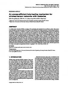
Figure 1. Interference cause by hidden terminal problem: (a) RTS/CTS exchange with pmax (b) Data/ACK exchange with pc .
Fig. 1 illustrates an example of the interference cause by hidden terminal problem when applying the power control mechanism. Suppose that T would like to transmit data to R. In Fig. 1(a), T uses pmax to transmit RTS and R replies CTS with pmax as well. The gray region is IR(r, max). Here, r is the lowest rate. T 0 is a hidden STA and is not aware of the transmissions of T and R since T 0 overhears neither T ’s RTS nor R’s CTS. T 0 is also out of the interference range of R. In Fig. 1(b), T and R use a reduced power, pc , to exchange data and ACK. Since the power is reduced, the IR of R is expanded as well, like the gray region in Fig. 1(b) shows. Obviously, T 0 is within the expanded interference range. Because T 0 is not aware of the transmissions of T and R, T 0 is very likely to interfere with the receiving of R if T 0 starts to transmit. As mentioned above, some of energy efficient routing protocols takes BER inferred from SNR as the routing metric. However, comparing the cases in Fig. 1(a) and (b), R will be interfered in (b), whereas not in (a) even through R has the same SNR after receiving RTS. The example shows that SNR is not sufficient to be the routing metric.
2.2. Related Work Many energy-efficient routing protocols have been proposed for wireless ad hoc networks [1, 8, 9]. Some of them applies the power control mechanism to decrease the energy consumption for data transmission. In [8], the energy consumption for end-to-end and hopby-hop retransmissions was analyzed for route selection. [8] further took the energy consumption for control packets into consideration. In [9], a progressive energy efficient routing protocol (PEER) was proposed. PEER applied power control mechanism, in which RTS/CTS are transmitted at the maximum power level while the data and ACK are transmitted at the minimum required power lever. PEER required
STAs to set their NAVs (Network Allocation Vector) to the EIF (Extended InterFrame Space) duration to avoid neighboring STAs issuing any signal. In [1], STAs are assumed to use minimum power to send data and estimate data retransmission probability based on the packet error rate. Although the above papers consider the energy consumption for data retransmissions, the interference due to the hidden terminal problem does not be considered, as mentioned in Section 2.1. Moreover, STAs applying aforementioned papers can not use higher transfer data rates to transmit their data when the channel condition is good. As the result, the network throughput decreases.
3. CLE2 aR2 : A Cross-Layer Energy-Efficient and Reliable Routing Protocol In this section, the Cross-Layer Energy-Efficient and Reliable Routing Protocol (CLE2 aR2 ) protocol is presented. Basically, CLE2 aR2 is modified from the Ad-hoc On Demand Distance Vector Routing (AODV) [3]. Instead of using the hop count as the routing metric, CLE2 aR2 use a new routing metric which takes the energy consumption in multi-rate networks into account. In the following, the new routing metric is introduced. Then, the modification of AODV is presented.
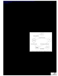
3.1. Link Cost Estimation CLE2 aR2 is a cross-layer design routing protocol, which estimates SNR at the physical layer, determines the usable transmission rates and power levels at the MAC layer, and calculates the energy consumption of a link which may be a part of a route. Assume that a STA sends RTS/CTS with the maximum power level, which is used to restrain the other STAs in its transmission range from issuing any signal to interfere the receiver of the station. However, when applying the power control mechanism, the interference range may be larger than the transmission range, as shown in Fig. 1. For a receiver, STAs in its interference range but not in its transmission range may issue signal to interfere the current transmission. For a transmission pair T and R, let AT and AR are the circle respectively centered at T and R with radius T R(max). T transmits data with the controlled power pc at the data rate r. Clearly, AT and AR are the areas on where STAs can receive RTS from T or CTS from R. Suppose that T use pT with rate r to transmit data and let A(r,c) be the circle centered at R with radius IR(r, c). Therefore, if the STAs in A(r,c) − (AT ∪ AR ) issues any signal, the current transmission pair will be interfered, as shown in Fig. 2. However, the receiver is unable to know how many STAs locate in A(r,c) − (AT ∪ AR ) and which of them will is-
A (r,c)
S = n0 and D = nk . Therefore, the total cost, ρi , consumed along Ri can be presented as follows.
IR ( r,c )
TR
(m
TR
ax)
T
(m
R
AT
ρi = ax
Figure 2. A(r,c) − (AT ∪ AR ). sue signal. The method used by CLE2 aR2 to estimate the number of STAs issuing signal in A(r,c) − (AT ∪ AR ) is as follows. Because R can not communicate with STAs in A(r,c) − (AT ∪ AR ), the density of STAs in R’s transmission range, denoted as δR , is used to estimate the number of STAs locating in A(r,c) −(AT ∪AR ). Therefore, the number of STAs locating in A(r,c) − (AT ∪ AR ) can be expressed as [A(r,c) − (AT ∪ AR )] ∗ δR . Assume that a STA which has transmission demands λ around a period of time follows a Poisson distribution. Let Ptx be the probability that a STA has demands to send a packet around a period of time. Therefore, the probability of the STAs , denoted as P(r, c), which may interfere the current transmission pair with the controlled power pc at the data rate r, can be calculated through the Eq. (3). (3)
Therefore, the number of data retransmissions can be estimated by Eq. (4). 1 . P(r, c)
(4)
As the result, when T transmits data to R with controls power pc , the relaying cost of transmitting a unit of data from T to R can be regarded as follows: ldata , (5) r where ldata is the message length of the data transmitted from T to R. When receiving a RTS/CTS, a STA can estimate the distance between the transmitter and itself. Then, the STA can infer the power levels and the data rates which can be used by the transmitter.According to Eq. (5), the STA can determine which power level and data rate should be used such that the transmitter can transmit its data with lower energy consumption. Assume that existing the ith route Ri = n0 → n1 → ... → nk from the source STA S to the destination STA D, where, without of loss of generality, ρ(r, c) = n(r, c) ∗ pc ∗
(6)
where rj and cj are respectively the data rate and the power level used by nj to communicate with nj+1 . ρ(j,j+1) (rj , cj ) is the relaying cost between transmission pair nj and nj+1 . Suppose that there are w routes from S to D. The minimum energy consumption route Rmin would be
AR
n(r, c) =
ρ(j,j+1) (rj , cj ),
j=0
)
P(r, c) = 1 − (1 − Ptx )[A(r,c) −(AT ∪AR )]∗δR .
k−1 X
Rmin = arg min(ρi ), i = 1, 2, ..., w.
(7)
3.2. Route Discovery and Maintenance CLE2 aR2 is based on AODV, but uses ρ as the routing metric. CLE2 aR2 is composed of two parts, route discovery and maintenance. The route discovery is for a source STA to find an energy efficient route. In order not to have too long route setup time, the destination STA does not decide the route until all Route Request (RREQ) messages are received. However, the selected route may be not the most energy efficient one. Therefore, in the route maintenance, the STAs on or near by the route will issue a modifed Route Error (RRER) message to change the route such that the data can be forwarded to the destination STA with lower energy consumption. The details of these two parts are as follows. The route discovery of CLE2 aR2 is a little different from that of AODV. When a source STA S, wants to find a route to a destination STA D, S will broadcast a RREQ message. Any STA, termed as R, which is the first time to receive the RREQ from T records S, T , D, and route cost in a routing table after R determines the relaying cost from T to R. Then, T rebroadcasts this RREQ to its neighboring STAs. However, the relaying cost from T to R may not be the lowest. R may find other routes with lower relaying cost once receiving other RREQs. The intermediate STA will updates its routing table and rebroadcast the receiving RREQ which indicates another lower cost route. The method can help D to determine a much energy efficient route. Comparing to the energy consumption for the data retransmissions, that for the flood of these extra RREQs is much worthy. Similarly, D may receives many RREQs. However, D should not determine the route S that uses after receiving all RREQs because it needs long route setup time. Therefore, D applying CLE2 aR2 will sets up a timer after receiving the first RREQ message. Once the timer is timeout, D selects the lowest energy consumption route so far and reply a Route Reply (RREP) message to S. Although the selected
message wiil be issued by C when:
B
S
C
A
D
( a) B
S
C
A
D
( b)
Figure 3. Route maintenance issued by the STA (a) on or (b) near by the route.
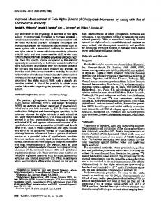
route may be not the most energy efficient route, the route is still near the best one with shorter route setup time [9]. Because the channel condition varies quickly, the route selected during the route discovery does not be the most energy efficient one during the data transmission phase. Therefore, the route maintenance is needed in such an environment. The route maintenance is triggered by STAs on or near by the route. There are two schemes in the route maintenance. The examples shown in Fig. 3 demonstrate these two schemes in the route maintenance. In Fig. 3 (a), there is a path S → ... → A → B → C → ... → D. Because C can overhear the transmission from A to B, C can estimate the relaying cost from A to C. In addition, C can estimate the relaying cost from B to C because the exchange of RTS/CTS. However, C does not know the cost from A to B. Therefore, in CLE2 aR2 , B is required to add the relaying cost between A and B to the data packet such that C can know the information. Once receiving the data from B, C use RRER message to ask A to update its routing table if Eq. (8) is meet. As the result, A will directly forward the data to C when receiving RRER from C. ρ(A,C) (rA , cA ) < ρ(A,B) (rA , cA ) + ρ(B,C) (rB , cB ), (8) where ρ(T,R) (rT , cT ) is the relaying cost between STAs T and R with the controlled power pT at the data rate rT . On the other hand, in Fig. 3 (b), A directly forwards the data to C. Because B overhears the packet from A to C, B can estimate the cost from A to B. Moreover, because C will add the relaying cost from A to C into the data packet for the next forwarder, B can know the relaying cost from A to C through overhearing. If B ever communicates with C, B’s routing table records the relaying cost from B to C. As the result, if the information is still fresh, B can determine whether the route should be changed according to Eq. (8). However, if B never communicates with C or the information in B’s routing table is out of date, B should issue a hello message to C such that C can estimate the relaying cost from B to C and report the information to B. The hello
ρ(A,C) (rA , cA ) − ρ(A,B) (rA , cA ) > Φth , ρ(A,C) (rA , cA )
(9)
where Φth is a threshold between 0 and 1. Φth is used to avoid a STA frequently issuing the hello message. That a STA arbitrarily issues the hello message is not a good strategy for the route maintenance. For one thing, if Eq. (8) is not met, the energy consumption for transmitting the hello message is wasted. For another thing, the route may oscillates between these two-hop STAs due to the varied channel quality. Therefore, Φth helps to decrease the number of unnecessary route maintenance which increases not only the energy consumption but also the media access competition.
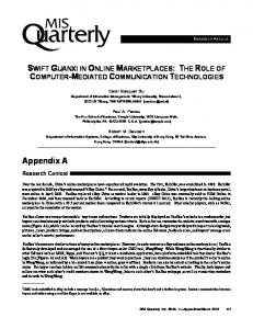
4. Performance Evaluations In this section, the performance of CLE2 aR2 is evaluated. CLE2 aR2 is implemented in the OPNET simulator [2]. CLE2 aR2 , MTRTP [8], and PEER [9] are compared in a randomly topology. STAs are assumed stationary and randomly deployed in a 700m ∗ 700m area. The application protocol is FTP (File Transfer Protocol). The packet size is assumed fixed and set to 1000 bytes. The transmission pair is randomly selected and the simulation time is 10 minutes. Fig. 4(a) illustrates the comparisons of CLE2 aR2 , PEER, and MTRTP in terms of average energy consumption to different number of STAs in the network. Clearly, CLE2 aR2 performs better than the others. Although the curves of CLE2 aR2 and PEER have similar inclination, CLE2 aR2 can still perform better than PEER because CLE2 aR2 can much accurately the link quality, which decrease the energy consumption for the data retransmission. Fig. 4(b) compares the end-to-end throughput of the protocols. Similarly, CLE2 aR2 performs better than PEER and MTRTP. Because CLE2 aR2 can efficiently decrease the number of retransmissions but uses higher data rates, CLE2 aR2 achieves higher end-to-end throughput. Since PEER takes the hop count as its primary routing metric to find the route, PEER uses lower data rate to transmit data. Basically, the difference of the end-to-end throughput among CLE2 aR2 , PEER, and MTRTP is not significant when the network density is low. However, when the network density increases, CLE2 aR2 can still perform well because CLE2 aR2 much accurately estimate the link quality and use higher data rate to transmit data. Fig. 4(c) shows the impact of the network density on delay time. As can be seen, when the network density increases, the curves of CLE2 aR2 , PEER, and MTRTP increase. Both CLE2 aR2 , PEER, and MTRTP has similar tendency; however, the delay time of PEER is the longest. Because the route maintenance is not considered in MTRTP,
5
10
15 20 25 Number of STAs
(a)
30
7 6
PEER MTRTP 2 2 CLE aR
7 6
5 4 3
5
Number of Retransmissions
PEER MTRTP 2 2 CLE a R
PEER MTRTP 2 2 CLE aR
8
Packet delay( s)
Network throughput( MB)
Average power consumption( mW)
80 75 70 65 60 55 50 45 40
4 3 2 1
2 5
10
15
20
25
30
Number of STAs
(b)
5
10
15
20
25
30
Number of STAs
(c)
3.0 PEER MTRTP 2 2 CLE aR
2.5 2.0 1.5 1.0 0.5 0.0 5
10
15
20
25
30
Number of STAs
(d)
Figure 4. Impacts of network density on (a) the average power consumption of STAs, (b) the end-toend throughput, (c) the packet delay, and (d) the number of retransmissions.
the route can not self-adjust when the channel quality become bad. As the result, when the network density is high, the delay time of MTRTP increases rapidly due to the high data retransmission probability. Fig. 4(d) compares the number of data retransmission of CLE2 aR2 , PEER and MTRTP in different network density. It can be seen that CLE2 aR2 can efficiency provide a more reliable route in different network conditions. Due to the lack of the route maintenance scheme, STAs applying MTRTP do not adjust their routes in the network with rapidly varied channel quality. Therefore, MTRTP incurred more retransmissions. For CLE2 aR2 and PEER, when the network density increases, the number of retransmission does not significantly increase. That is because PEER and CLE2 aR2 provide the route maintenance mechanism for a STA to forward data in a more reliable route. However, CLE2 aR2 provides better performance because CLE2 aR2 can accurately estimate the channel quality. The simulation results indicate that CLE2 aR2 is outperform than PEER and MTRTP in terms of energy consumption, end-to-end throughput, delay time and the number of data retransmissions through applying the power control and rate adaption mechanisms.
5. Conclusions In the paper, a cross-layer energy-efficient and reliable routing (named CLE2 aR2 ) protocol for wireless ad hoc networks is proposed. CLE2 aR2 takes power strength, data transfer rate, and interference into account to reflect the real situation of a varied wireless channel. A new routing metric is proposed to estimate the energy consumption for data retransmission based on these lower-layer factors. The routing metric is used in both the route discovery and the route maintenance to construct or maintain a more reliable route such that the data can be delivered to destination with lower energy consumption. Simulation results show that CLE2 aR2 can perform better than the other existing crosslayer routing protocols in terms of energy consumption, end-to-end throughput, delay time and the number of data
retransmissions.
Acknowledgements The work was supported by the National Science Council of the Republic of China under Grant NSC 96-2221-E032-017.
References [1] Q. Dong, S.Banerjee, M. Adler, and A. Misra. Minimum energy reliable paths using unreliable wireless links. In Proceedings of the ACM International Conference on Mobile Computing and Networking (MOBICOM), pages 449–459, May 2005. [2] OPNET Technologies Inc. OpNet Modeler 10.5A, 2004. [3] C. Perkins, E. Belding-Royer, and S. Das. Ad Hoc OnDemand Distance Vector (AODV) Routing. IETF Mobile Ad Hoc Networks Working Group, Internet Draft, October 2003. [4] T. Rappaport. Wireless Communications: Principles and Practice. Prentice Hall, New Jersey, 2 edition, 2002. [5] K.-P. Shih, Y.-D. Chen, and C.-C. Chang. Adaptive rangebased power control for collision avoidance in wireless ad hoc networks. In Proceedings of the IEEE International Conference on Communications (ICC), pages 3672–3677, 2007. [6] H.-C. Wang and Y.-H. Wang. Energy-efficient routing algorithms for wireless ad-hoc networks. In Proceedings of the IEEE International Symposium on Personal, Indoor and Mobile Radio Communications (PIMRC), Sept. 2007. [7] F. Xie, L. Du, Y. Bai, and L. Chen. Energy aware reliable routing protocol for mobile ad hoc networks. In Proceedings of the IEEE Wireless Communications and Networking Conference (WCNC), pages 4316–4320, 2007. [8] J. Zhu, C. Qiao, and X. Wang. A comprehensive minimum energy routing scheme for wireless ad hoc networks. In Proceedings of the IEEE INFOCOM, the Annual Joint Conference of the IEEE Computer and Communications Societies, volume 2, pages 1437–1445, Mar. 2004. [9] J. Zhu and X. Wang. PEER: A progressive energy efficient routing protocol for wireless ad hoc networks. In Proceedings of the IEEE INFOCOM, the Annual Joint Conference of the IEEE Computer and Communications Societies, volume 3, pages 1887–1896, Mar. 2005.


![[a]fl2 - Semantic Scholar](https://m.moam.info/img/260x300/afl2-semantic-scholar_5b923311097c4704758b456f.jpg)