ClickWatch – An Experimentation Framework for Communication Network Test-beds Markus Scheidgen Anatolij Zubow Robert Sombrutzki Humboldt University Humboldt University Humboldt University Rudower Chaussee 25 Rudower Chaussee 25 Rudower Chaussee 25 Berlin, Germany Berlin, Germany Berlin, Germany Email:
[email protected] Email:
[email protected] Email:
[email protected]
Abstract—It is hard to experiment with test-beds for communication networks: data produced in the network has to be retrieved and analyzed, networks must be reconfigured before and between experiments, data is often little structured (log-files) and analysis methods and tools are generic. Even though many problems of experimentation are the same for all experiments, re-use is sparse and even simple experiments require large efforts. We present a framework that attempts to solve these problems: we define a set of requirements for experimenting with network test-beds, we describe the principles and inner workings of our framework, demonstrate it with two typical example experiments, and present measurement results that illustrate the feasibility and scalability of our approach. Some qualitative and quantitative aspects of ClickWatch are compared to the commonly used logfile based approach to experimentation. Keywords-Communication networks, Test-bed, Click Modular Router, Experimentation framework
I. I NTRODUCTION Wireless and wired communication networks are an important research topic in industry and academia. Significant efforts in the academic world are made to provide realworld prototypes and test-beds based on open source software and off-the-shelf technologies mostly based on standards like IEEE 802. In the academic world the Click Modular Router API [1] has established itself as a pseudo-standard for building software for communication networks (e.g. wireless mesh networks). One of the main research tasks in this area is the development of new or improved network protocols. This requires an experimentation platform or framework. ClickWatch is an experimentation framework for network test-beds 1 . The central aim of ClickWatch is to mask the complexity of a dynamic distributed network system such as a communication network consisting of hundreds of nodes. For a user such a network of nodes appears as a simple centralized software system. This allows to accomplish the challenging task of setting up experiments in large testbeds and allows to analyze them in a simple way. From the technical point of view ClickWatch is based on Eclipse and the Eclipse Modeling Framework2 . ClickWatch 1 http://hwl.hu-berlin.de/ 2 http://eclipse.org/modeling
allows to analyze and control communication network testbeds programmed with the Click Modular Router API. The Click API is a C++ based component model specially designed for describing router configurations. ClickWatch accumulates data from multiple network nodes. The status of the network as well as the generation of derived data, e.g. reports and network statistics, can be easily accomplished using a modeldriven transformation approach. With the help of a graphical interface, ClickWatch accelerates the software development process. The status of the network can be analyzed at runtime so that the user is able to adapt his experiment to the changing network test-bed environment. II. P ROBLEM S TATEMENT Experimentation with real-world networks (test-beds) is hard. A network test-bed is a distributed system. To analyze its functional and non-functional characteristics four task must be performed. First, data has to be produced on the different network nodes (measurement). Secondly, this distributed data needs to be collected and merged into a single, centralized, coherent representation. Thirdly, the centralized data needs to be analyzed. This means that the different pieces of data, produced on different nodes and at distinct moments in time have to be aggregated, put into a more abstract representations (e.g. statistics), and interpreted. Fourthly, to set up the next experiment, you need to reconfigure network nodes. These four tasks contain elements that are specific to distinct experiments, e.g. syntax and semantics of the data that is produced, but the tasks also contain elements that are equal for all experiments, e.g. how data is centralized. We propose a framework that reduces experimentation effort to experiment specific elements and provides all re-occurring elements of experimentation in the domain of computer communication networks. III. R EQUIREMENTS We distinguish between functional (what) and nonfunctional (how) requirements. Before we can list requirements, we have a closer look at the process of experimentation. This will refine the problem statement (ref. II) and give us more substance to derive requirements from. Based on this process description, we will derive functional requirements
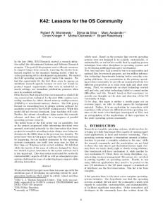
adapting the network
gained knowledge
Adapt Measure collecting data
Fig. 1.
transforming data into information
Experimentation process.
and those non-functional requirements that determine the user’s (experimenter’s) experience. Furthermore, we list nonfunctional requirements that stem from the technical limitations in the domain of computer communication networks. A. Experimentation as a Process We envision experimentation as a process similar to agile software engineering. We want to produce first results fast and with little preparation. These results are later refined in continuous cycles of experimenting, observation, analysis, and adaption. The whole cycle is driven by the same framework. Promising threads of experiments can be conducted fast, and dead ends can be discovered soon and without putting unnecessary efforts into them. Fig. 1 shows the natural way of conducting experiments as a cycle. Suppose you start your research with a simple idea, manifested in a first hypothesis that you need to prove or disprove by an experiment. The natural thing to do is to conceive a procedure, which when run (experimentation), leads to an observation that when revised through careful analysis, either supports or neglects the hypothesis. This result of you experiment leads to a revised hypothesis that you need to prove with a new experiment which is an adaptation of the last experiment. Research becomes a cyclic execution of experiments, where each cycle consists of four tasks: experimentation, observation, analysis, and adaptation. In agile software engineering the major assumption is that it is impossible to tell all requirements for a software before the software is build and used. Applied to experimentation, this assumption is that it is impossible to conceive a major, probably game changing hypothesis, before having conducted an experiment (or a series of experiments) that lead towards it. An experimentation framework needs to support the idea to start with simple experiments, where the (often unexpected) results inspire the hypothesis for the next experiment. This requires a framework that makes experimentation, observation and analysis extremely effortlessly. As a result, it is more likely to conceive and run multiple simple experiments, where the results of one experiment lead to the next one, than to think of ”the one” big experiment. What does experimentation mean in the domain for computer communication networks? We need to look what the four elements of experiments (experimentation, observation, analysis, and adaptation) are in this particular domain.
Firstly, experimentation: In the computer communication network domain, experiments with actual networking components (i.e. everything that is not a simulation) consist of a setup of network hardware and software. Based on this setup the network is put into action by running of some sort of sample network traffic. Secondly, observation: This usually means the collection of network statistics on all protocol layers. Thirdly, analysis: Usually consists of aggregating network statistics into statistics on a higher level of abstraction. Comparing result to some sort of benchmark, e.g. the results of other experiments. Fourthly, adaptation: Based on the results of an experiment, one wants to adapt software and/or hardware configurations, network traffic, etc. B. Functional Requirements Of course, the four tasks listed in the problem statement are reflected within the experimentation process and the experimentation framework needs to support those tasks: (1) network nodes must be able to produce data, (2) the data must be collected from those nodes into a centralized representation of the network, (3) the collected and centralized data must be analyzed, and (4) it must be possible to reconfigure the network based on interpretation of prior analysis results. To support the agile experimentation envisioned in the process description, the framework should allow to start analysis during the running experiment. The framework should support persistence of collected data and analysis results to enhance the reproducibility of experiments. The framework should allow to automate the experimentation process as much as possible. C. Qualitative Requirements (Users Perspective) To develop experiments quickly and in an evolving manner it is paramount that the data produced and analyzed can be easily understood and its meaning is clear at all times. Therefore the first and central requirement is that the handled data is structured and that this structure is visible whenever the user is confronted with this data. Furthermore, these structures must be extensible with little effort in order to evolve from one experiment to the next. When the user accesses data (e.g. during analysis) this should only be possible according to the structure, i.e. in a type-safe manner. This lowers human error and safes valuable time and resources. This can also be taken as common sense from experience in software engineering. Experiment specific artifact created by users should be reusable. Methods used, especially to produce and analyze data, should support a compositional paradigm (e.g. objectorientation). Experimentation, especially putting several experiments into a single workflow, also means that the network nodes can be modified between experiments. Modifications on network nodes (i.e. adjusting protocol parameters) should be done along the structures used in producing data. It should be possible to automate modification of network nodes. Furthermore, the whole experimentation process needs to be automatable.
D. Quantitative Requirements (Technical Perspective) We are experimenting with network nodes that are limited in networking and computing capabilities and furthermore these capabilities are part of the characteristics we want to measure during experimentation. Therefore, it is necessary for an experimentation framework to put as little load on these capabilities. This means production of data on a node should cost as little CPU load as possible. The data produced and transported should have a footprint small as possible. Networks consisting of many nodes can quickly produce large amounts of data. The data collected should be stored tightly. To make the experimentation framework scalable, it is necessary that collection and storage of data is itself distributable. It must be possible to analyze data in a timely fashion. Data needs to be indexed according to its structure to allow quick access to distinct pieces of data. IV. P REREQUISITES The experimentation framework ClickWatch is based on network nodes that run on MIT’s Click Modular Router API. In this section, we briefly introduce Click and the specifics of how we use it. A. Click Modular Router The main prerequisites to use ClickWatch are that the used network components are programmed with the MIT Click API [1] and run in a corresponding runtime environment. A Click router is built by sticking together several packet processing modules, called elements, forming a directed flow graph. Each element is responsible for a specific task such as packet classification, scheduling, or interfacing with networking devices. Click comes with an extensive library of elements supporting various types of packet processing. Such a library allows to easily write new router configurations by simply choosing the elements to be used and the connections among them. Finally, a router configuration can easily be extended by writing new elements. Click elements provide handlers, allowing to read and write properties remotely. Handlers are the concept to produce data on the nodes (read handler) and to modify a nodes behaviors (write handler). B. XMLized Handlers Originally Click handler values are strings. Of course, strings can be used to encode complex structured data. While the shipped Click elements to not facilitate this, we extensively use XML as handler values. The inherent structure of XML serves two purposes: (1) values and their structure can be visualized in ClickWatch as a tree, differences between handler values can be broken down to single XML elements; (2) when analyzing data (i.e. handler values), we can use the inherent structure to provide an API that allows the type-safe access of single XML elements, rather than starting to parse plain text strings manually.
As an example consider the LinkStat element shipped with Click. Its purpose is to track broadcast loss rates to neighboring nodes which can be obtained by calling a handler called bcast stats. In the original version of Click the output of this handler is plain text (Listing 1). The output of the modified XMLized version of this handler is given in Listing 2. C. Meta-Data for Handler Values Handler values that are represented as XML have an inherent predefined structure. Even if this structure is not explicitly defined (e.g. through an XML Schema definition 3 ), values of the same handler, always have the same structure. Analyzing such values means to programmatically dissect values into the contained pieces of data. This programming effort can be reduced, when explicit meta-data, e.g. an XML Schema definition, is present. In ClickWatch, we use such meta-data to generate Java-APIs for each handler that allows navigation through the structure of such values, based on concrete XML element names. Within an IDE (e.g. eclipse) programming with handler values becomes faster and safer due to code completion and static analysis of code based on the specific XML structure for specific handlers. The meta-data can be provided in two ways: explicitly (manually) and inferred (automatically). Explicit definition of meta-data means each element has a specific handler that returns a XML Schema definition of all the other handlers of this element. This handler has to be programmed. Using the inferred meta-data approach, ClickWatch assumes that the internal structure of values of the same handler does not change, and it automatically guesses the meta-data based on the reoccurring structural elements it witnesses in actual handler values. This means no additional programming efforts. D. Compound Handler ClickWatch reads handler values remotely to collect data. There are different strategies to retrieve handler values from nodes. Per default, Click supports to read handlers remotely, one handler at a time (Baseline). Since Click configurations can easily consist of hundreds of handlers, this strategy requires several hundred distinct requests to download a snapshot of the nodes current state. This limits the possible rate at which ClickWatch can retrieve data. Especially in large networks with a slow backbone communication network (e.g. IEEE 802.11) the sample rate would be very low. We build a Click element, called compound handler, which allows us to reduce the amount of generated requests. The compound handler provides a readable handler that can provide all values of all handlers of the network node. This allows ClickWatch to read all handler values with a single request. The compound handler composes all handler values into one piece of XML. The compound handler has three different operating modes. First, the compound handler collects all values from all the handler at the moment it is read (onCH). Secondly, the compound handler collects and records values at a specific sample 3 http://www.w3.org/XML/Schema
Listing 1.
Output of handler bcast stats
06−1B−B1−05−3B−8E fwd t a u =100000 num rx =81 p e r i o d =1000 . . . −− r e v t a u =100000 num rx =90 p e r i o d =1000 . . . # many more l i n e s
Listing 2.
Modified output of handler bcast stats
rate internally. When read, it returns the values collected since it was last read (CH). Thirdly, the compound handler also collects and records values internally, but only provides the handler values that have changed (∆CH). Another strategic aspect of pulling handler values is the chosen update rates. You might want to have different handler values are higher or lower update intervals. Therefore, the compound handler allows to select different internal update intervals for different handlers for the CH and ∆CH modes.
Network subNetworks nodes Node address: String port: String
A. ClickWatch’s General Mode of Operation The basic idea of ClickWatch is to observe network nodes in real time by reading their handler values. ClickWatch pulls handler values: it uses ClickControl to initiate requests towards network nodes. ClickWatch does so continuously and creates a centralized close to real-time representation of the current network state. We call this centralized network representation a network model and a network model that represents a node’s or network’s state at a specific moment in time a snapshot. Handler values can also be recorded over time: the dynamics of the network are covered as a series of snapshots. Sequences of snapshots are stored in a database and form a dynamic network model. ClickWatch uses transformation techniques (such as XSL transformations) or handler specific Java APIs to analyze single snapshots or recorded dynamic network models. ClickWatch also allows to change write handler values and to deploy new Click elements and therefore allows to adapt
childElements
getHandler(String):Handler handler Handler name: String timestamp: long canWrite: boolean canRead: boolean value: Object
V. C LICK WATCH Figure 2 shows the overall architecture of the ClickWatch framework. It consists of the network nodes (1), that run on Click and preferable contain a compound handler (2); ClickControl [1], a Java API that allows to read hander values remotely (3); a database that records handler values (4, ref. to V-D); the ClickWatch GUI used to represent the current network state, or a moment in time recorded in the database (5, ref. to V-E); Eclipse based tooling for XSL used to analyze data in XML form (6); and Eclipse based tooling for Java (and other model transformation languages) used to analyze data in EMF form (7, ref. to V-F).
Element name: String
Fig. 3.
The ClickWatch type model (meta-model).
the network. This can be done manually via ClickWatch’s GUI or programmatically through the handler specific Java APIs. B. ClickWatch Model Click collects data from nodes and creates a centralized representation from this data called network model. This model is typed, i.e. each element in this model has a type. Network models are based on a type model (so called meta-model) that defines the types and their relationships. A network model comprises of networks that can contain nodes, nodes that can contain elements, elements that can contain other elements or handlers, and handlers that can contain values. When metadata for handler values is given (ref. to IV-C), the type model is canonically extended with the types in this meta-data. Figure 3 shows the meta-model for ClickWatch’s network models. Based on the type models nature, a network model is always a tree. Using model transformation techniques during analysis allows you to create models of other type models (e.g. a meta-model for topologies). Node identities used in handler values (such as IP- or MAC-addresses) can be used to resolve references between different handlers of different nodes. The network model becomes a graph and one can navigate the network model easily. Technically, network models are EMF models. EMF, the eclipse modeling framework, provides different facilities to create, edit, and program with models. Among those are treebased editors, which we use for ClickWatch’s GUI (ref. to
5 1
Click API software XSL
6
refer to Listing 4
Compound Handler
Element
XML
4
HBase “Big-Table” Data Base [node] [handler] 192.168.3.117 bcast_stats
[timestamp] 17:03:05,918
192.168.3.117 bcast_stats 192.168.3.117 bcast_stats 192.168.3.117 bcast_stats
17:03:06,120 17:03:06,321 17:03:06,321
Element
Fig. 2.
[value] ... ... ... ...
intent visualisation e ects
collect / adapt
transform
7 refer to Listing 5
XTEND OCL
Overall ClickWatch Architecture.
meta-model
reality
Handler Specific API
2
EMF
Click Control
Network Interface
Handler
3 Element
manipulates
model
Fig. 4. ClickWatch creates a (close to) real-time model of the network, visualizes it and allows to manipulate it.
V-E), and facilities to generate Java API’s for programming with models, which we use to program during analysis (ref. to V-F). Furthermore, XML is EMF’s build in serialization format, which we use to apply XSL transformation on network models (ref. to V-F). C. Updating the ClickWatch Model ClickWatch updates the network model continuously with fresh data from the nodes. Element and handler information, i.e. what elements and handler exist in a node, are collected once and afterwards new handler values are pulled constantly. Depending on compound handler usage (ref. to IV-D, updates are pulled at constant sampling rates (Baseline and onCH modes), or update intervals can be configured for each handler individually (CH and ∆CH modes). New handler values are merged into the existing network model. During this merge, differences can be tracked and shown (even down into the structure of handler values). The network model also listens for user changes. This means that user modification of handler values are detected; changed handler values are automatically written back to the affected network node. Therefore, allowing users to watch and change the network. This approach to watch and modify a network through a (close to) real-time model is illustrated in figure 4. D. Recording with ClickWatch In order to analyze network dynamics, ClickWatch records handler values over time. Instead of merging new handler
values into the existing network model, ClickWatch can also store each collected value into a database. The contents of this database can be used in two ways. First, you can watch the recorded network through the same GUI that is used to watch a network live. You can jump in time, i.e. set the network model to a specific snapshot, playback the network, and compare two network snapshots. Secondly, you can programmatically access the data for analysis, in the same way that you can access non dynamic models. You can access specific points in time, or create iterators that deliver all, or selected handler values in the order they were recorded. All handler values are timestamped on the network nodes. If clocks on network nodes are reasonably synchronized, these timestamp can be used during analysis to align data from different nodes. ClickWatch uses Apache HBase as database4 . HBase is an open-source implementation of the Google big-table database [2]. In difference to the more commonly known relational databases, HBase is focused on storing large amounts of data of the same kind in big tables rather than storing different types of data and their relationships. The resulting advantages are fast insertion of data, databases can be distributed, and automated indexing and retrieval of data values. The first two advantages are key in recording a network. A common Click configuration for a wireless mesh network used in our lab, consist of 200 handlers. When collected each 200 ms nodes produce roughly 3MB handler values per second. Even moderate network sizes could exceed the networking and hard disk IO capabilities of a single recording computer (also refer to VII). To index data, HBase puts the rows of a table into the order of their keys. Secondary indexes (tables containing keys of other tables as values) or possible. Values can be scanned efficiently by going through the index from smaller keys towards bigger keys. Since each key, is a byte array of arbitrary length, multiple properties can be coded into a key. ClickWatch uses node IDs, handler names and timestamps to compose keys. We hold different indexes with keys that use node IDs, handler names and timestamps in different order. Keys 4 http://hbase.apache.org/
network element
node
child element
handler XML-value
changes since last update
accessing an element’s attributes and possible child elements. Listing 5 demonstrates such an generated API. Compare to the XML representation of a network model in Listing 3 and you can find getter-methods for corresponding XML elements. With an integrated XSL editor, XSL transformation scripts can be created and executed on ClickWatch models. There are several specific transformation languages originally created for model transformations in software engineering that can be used on EMF-models and therefore can be used on network models. Some of these languages are specifically tailored for creating structures, e.g. network topologies6 [3], [4]; some or made for constraint evaluation [5]; other techniques are tailored for code generation7 . A combination of such languages allows us to quickly filter, aggregate, and further elaborate raw data from handler values and codegenerate this data into scripts for further analysis (e.g. in MATLAB). VI. E XAMPLE E XPERIMENTS With the following two example experiments, we want to illustrate ClickWatch’s potential for research. Both examples are drawn from the area of wireless communication. A. WiFi Link-level Measurements
Fig. 5.
Typical network model as represented in the ClickWatch editor.
composed in the order [node ID][handler name][timestamp] for example allow to scan through the values of a specific handler of a specific node in the order they were recorded. The order [node ID][timestamp][handler name] on the other hand, can be used to scan through the entire snapshots (all handler) of a specific node. E. The ClickWatch GUI ClickWatch presents itself to users with a graphical user interface. In its center is the so called ClickWatch editor, which shows a tree-based representation of the network model. The editor allows to create networks with nodes and their respective network addresses and Click runtime port. Figure 5 shows the different elements of a network model as represented in a ClickWatch editor. F. Analyzing Data Technically ClickWatch models are both eclipse EMF models and XML documents. That leaves us with a variety of technical possibilities to analyze. The most obvious methods to describe an analysis are programming with general purpose languages (e.g. Java), using XSL-transformation5 utilizing the XML-nature of ClickWatch models, or using specific transformation languages on the EMF nature of ClickWatch models. Through EMF and handler meta-data (ref. to IV-C), ClickWatch can generate a statically type-safe API for accessing and analyzing handler values, specific to the XML structure of concrete handler values. Such APIs basically map XML elements into interfaces that provide getter/setter-methods for
In the following, we show how easily ClickWatch can be used to analyze a complex relationship between multiple variables. We know from the theory of wireless communication that there is a strong correlation between Signal-to-Noise Ratio (SNR) and Packet Delivery Rate (PDR) value of a wireless link. However, for IEEE 802.11 systems lots of researchers observed only a weak correlation. From the literature we know that interference from WiFi and/or non-Wifi sources can be the cause for the observation of lots of links having a good SNR but only intermediate PDRs [6]. To confirm or disprove this hypothesis we set-up an experiment where we measured the PDR and SNR of each link. In addition we also measured the channel utilization at the receiver end. Since high channel utilization indicates high interference, we should observe that the SNR-PDR correlation is weaker in cases of high channel utilization. Listing 3 shows a fragment a our network model in ClickWatch’s XML representation. We can identify two Click elements: link stat and cst. The first one has a handler called bcast stats which stores PDR information on each incoming link. The second one has a handler called stats which returns information on the channel utilization at the node (phy/@hwbusy) as well as the SNR of each incoming link (nb/@snr). Listing 4 and Listing 5 show two possible ways to analyze the network model in Listing 3 using XSLT and Java. Both examples create a 3-column matrix that represents the SNR, PDR and channel utilization of each link. Afterwards, the generated data can be imported in MATLAB and visualized via a scatter plot (Listing 6). The scatter plot shows the 6 http://eclipse.org/m2m/
5 http://www.w3.org/Style/XSL/
7 http://eclipse.org/modeling/m2t/
< s t a t s name=” s t a t s ” canRead =” t r u e ”>
Listing 3.
Fig. 6.
XML Network model.
Result of the LLM experiment, generated with ClickWatch.
relationship between SNR and PDR while the color of a marker represents the channel utilization: a blue and a red color mean a low and a high value respectively. From the generated result (Fig 6) we can see that there is a significant impact from channel utilization and therefore interference on the SNR/PDR relationship. % i m p o r t data from f i l e load da ta . t x t % plot colormap ( j e t ( 1 0 0 ) ) ; s c a t t e r ( d a t a ( : , 1 ) , d a t a ( : , 2 ) , 50 , d a t a ( : , 3 ) , ’ f i l l e d ’ ) ; caxis ([1 100]); colorbar ; t i t l e ( ’SNR v s . PDR v s . C h a n n e l Load ’ ) ; x l a b e l ( ’SNR ’ ) ; y l a b e l ( ’PDR ’ ) ;
Listing 6.
MatLab script for LLM.
B. Global Path Selection The following describes a more complex experiment, where we not only retrieve data from nodes, but also modify handler values on the nodes. Conventional network routing protocols use a shortest path algorithm (e.g. Dijkstra) to find a path from source to destination with respect to some path metric. The majority of known path metrics tries to minimize the cost of end-to-end packet delivery by either reducing the number of required hops, packet transmissions, or delay. The basic idea is that if each node minimizes the costs of its own packet flow the entire network will benefit. The disadvantage of such methods is that they respond inadequately to the specifics of the used wireless technology. For example, the efficiency of a protocol like IEEE 802.11n strongly depends on packet size. Small packets like VoIP packets cannot benefit from PHY improvements introduced in 802.11n because the PHY header as well as control packets (ACK/RTS/CTS) are always send on a robust PHY rate (6 Mbps). Only the payload can be send on a maximum data rate of up to 600 Mbps. The efficiency can be easily improved when multiple small packets are aggregated with each other and send as a single frame. This advantage is especially high for small packets like VoIP where it is possible to pack multiple VoIP packets in a single frame. Existing literature provides only few approaches where nodes coordinate their path selections with each other in order to gain from packet aggregation. The reason lays in the algorithmic complexity of a distributed solution for cooperative path selection: each node needs to know the ongoing packet flows in the network and the nodes need to agree on the paths to be used. A distributed solution causes lots of communication overhead between nodes, resulting in additional network load. Cooperative path selection based on global knowledge, on the other hand, is easy. Therefore, we suggest to measure the possible gain of cooperative path selection with simple algorithms based on global knowledge, before investing into a distributed solution. Only when the expected gain is higher than the estimated costs of a distributed solution, one should actually implement a distributed version of cooperative path selection. In the following ClickWatch is used to quantify the gain of the proposed cooperative path selection by realizing a global path selection: a computer running ClickWatch obtains global knowledge and calculates the path for each flow. Fig. 7 shows the distinct steps in this experiment. ClickWatch periodically collects the local network topology from each node. From this local data a global network topology is calculated. In addition, ClickWatch schedules the packet flows according to some network traffic flow model. With the help of the global network topology as well as the information about all flows (source, destination, average packet size) ClickWatch is able to compute the best path for each packet flow with respect to the characteristics of the PHY layer (e.g. packet aggregation). The calculated paths are injected back into the routing tables of the nodes using write
< x s l : s t y l e s h e e t v e r s i o n =” 1 . 0 ” x m l n s : x s l =” h t t p : / / www. w3 . o r g / 1 9 9 9 / XSL / T r a n s f o r m ”> , ,;
Listing 4.
XSLT script for LLM.
p u b l i c c l a s s L i n k L e v e l M e a s s u r e m e n t implements I C l i c k W a t c h M a i n { @Inject NetworkUtil networkUtil ; @Override p u b l i c v o i d main ( I C l i c k W a t c h C o n t e x t c t x ) { Network n e t w o r k = c t x . g e t A d a p t e r ( I C l i c k W a t c h M o d e l P r o v i d e r . c l a s s ) . g e t N e t w o r k ( ) ; f o r ( Node node : n e t w o r k . g e t N o d e s ( ) ) { B c a s t s t a t s b c a s t S t a t s = n e t w o r k U t i l . g e t S p e c i f i c H a n d l e r ( node , B c a s t s t a t s . c l a s s ) ; S t r i n g fromAddr = b c a s t S t a t s . g e t E n t r y ( ) . g e t F r o m ( ) ; for ( Link l i n k : b c a s t S t a t s . g e t E n t r y ( ) . g e t L i n k ( ) ) { for ( Link info l i n k I n f o : l ink . getLink info ( ) ) { Node t o = n e t w o r k U t i l . n a v i g a t e M a c A d d r ( n e t w o r k , l i n k . g e t T o ( ) ) ; i n t pdr = l i n k I n f o . getRev ( ) ; S t a t s s t a t s = n e t w o r k U t i l . g e t S p e c i f i c H a n d l e r ( to , S t a t s . c l a s s ) ; i n t chLoadRecv = s t a t s . g e t C h a n n e l s t a t s ( ) . g e t P h y ( ) . getHwbusy ( ) ; f o r ( Nb nb : s t a t s . g e t C h a n n e l s t a t s ( ) . g e t N e i g h b o u r s t a t s ( ) . getNb ( ) ) { i f ( nb . g e t A d d r ( ) . e q u a l s ( fromAddr ) ) { d o u b l e s n r = nb . g e t S n r ( ) ; System . o u t . p r i n t l n ( s n r + ” , ” + p d r + ” , ” + chLoadRecv ) ; } } } } } } }
Listing 5.
ClickWatch
Network
1: deploy click config. let network settle down
3.1 generate flows acc. to trafic model 3.2: calculate optimal path per flowwith algorithm X
7: calculate performance metrics (throughput, performance)
2: get local topology info.
4: inject paths 5: start flows 6: record stats (throghput, ...)
Java for LLM.
VII. E VALUATION In this section we present the results of measurements that we performed to show that ClickWatch yields the quantitative requirements from section III-D. First, we compare Click’s handler with the compound handlers, we introduced to enhance collection of large amounts of data at high sampling rates. Secondly, we show ClickWatch’s ability to record efficiently and to access recorded data quickly. Here, we compare ClickWatch with a typical log file approached favorited by many researchers. A. Compound Handler
8: alternate paths, algorithms, other parameter
Fig. 7.
Sequence chart for the global path selection experiment.
handlers. Finally, the packet flows are started simultaneously by ClickWatch. At the end of the experiment ClickWatch collects statistics like the achieved per flow throughput. By analyzing these data ClickWatch is able to quantify the gain of the proposed solution over a conventional path selection scheme.
In the following we evaluate the performance of the proposed compound handlers (Section IV-D) in terms of fetch time, network load and CPU usage (Fig. 8). Compared to the Baseline, i.e. retrieving the value of each handler separately, the proposed compound handler that collects samples locally and only transmits modified handler values (∆CH) is able to reduce the fetch time, i.e. the time it takes to retrieve the data from all handlers, by a factor of 25-33 depending on the total number of handlers. Moreover, the amount of network load is comparable with Baseline. Interestingly, the CPU utilization at the network load is lower compared to Baseline which can be explained by the reduced number of network requests.
20
50 0
50
100 150 Number of Handlers
200
Transfered kBytes
80 60 40
10
5
0
20
40
60
80 100 120 140 160 Experiment duration [min]
180
200
220
80 100 120 140 160 Experiment duration [min]
180
200
220
3
10
50
100 150 Number of Handlers
200
20 Baseline onCH CH ∆CH
15 10 5 0
Log−file Java/HBase 15
Baseline onCH CH ∆CH
20 0
CPU usage at node
Log−file/database size [GByte]
100
Baseline onCH CH ∆CH
Duration of evaluation [sec]
Fetch time (ms)
150
Log−file Java/HBase 2
10
1
10
0
10
−1
50
100 150 Number of Handlers
200
Fig. 8. Performance comparison of different compound handler implementations when using mesh nodes with fast CPU (Pentium 4, 3 GHz). The sample rate was 200 ms.
B. Log-File vs. Database To illustrate the capabilities of ClickWatch to record and analyze networks with an HBase database, we compare ClickWatch with the traditional log-file approach. A common way to analyze network data is to let each node dump log-files. These log-files are centralized through specific log-servers, shared NFS-volumes, or simply copied together. Later log-files can be analyzed with regular expressions; log-file analysis is commonly written in perl, awk, sed, grep, etc. For a comparison, we performed the following experiment. We let 10 Click nodes (wireless router that constitute a wireless mesh network) operate for different time durations. First, these nodes produce log-files. The log-files contain all the data of all handler values obtained every 200 ms. Each entry (line) in log-file line represents a leave in the XML of handler values. Each log-file line consist of a timestamp, a node id, a qualified handler name and all the attributes and texts in a path from the handlers XML root to the leave the log-file line represents. Moreover, lines do not contain any XML element names or other redundant strings. Secondly, we recorded the network state of the 10 Click nodes using ClickWatch and an HBase database using the same recording time and sampling. Afterwards, we performed an example analysis of the logged/recorded data. The aim of the analysis is to plot channel utilization of each network node. The log-files were solely analyzed with a script using Unix tools like grep, awk and sed. The HBase data was analyzed with a small Java program based on an API generated for the used Click configuration. The results are presented in Figure 9. Two aspects were analyzed. First, the required storage size for log-files and database respectively. Secondly, we measured the time it takes
10
20
40
60
Fig. 9. Comparison by storage size and analysis time for network data stored in log-files and in databases (hbase).
to perform the example analysis. The following observations can be made. The comparison of required storage sizes shows that in our case the HBase databases where roughly half the size of the log-files. The reason is that log-files contain lots of redundant data. In logfiles data is structured into lines and each line must bear a meaning on its own. Even when two lines only differ in a single number, the lines must contain much more than this number in order to make sense. This is different in XML. Data is structured into trees. Two leaves can only contain a single number (differ in this number) and still provide meaningful information through the common data of their ancestor nodes. See also the example log file and XML snippets in Listings 1 and 2. The comparison of analysis durations shows that an analysis based on HBase runs magnitudes faster than the log-file analysis. The data-base index allows to access the one handler of interest and neglect all others, where a log-file analysis has to scan through the whole record. It is safe to assume that this relationship will remain also for more complex analysis that requires multiple passes of log-file analysis. Qualitative the Java programmed analysis based on HBase is statically type-safe and through object oriented programming easily re-usable. The log-file approach on the other hand, usually means custom scripts that are often hard to understand and impossible to re-use. VIII. R ELATED W ORK Related work falls into three categories: Inspecting Click at runtime, model-based approaches for monitoring or introspection of distributed systems, and approaches in automating experimentation and scientific workflows in general.
A. Clicky 8
The Clicky GUI comes with Click. Clicky can show configurations of single Click router as text (with syntax highlighting) or diagrams, and can read and write handlers in live configurations. Output router diagrams can be exported. Furthermore the router configuration can be changed and redeployed. Clicky is suitable for training and teaching purposes, e.g. overflowing queues are visualized in the flow graph. The biggest disadvantage of Clicky compared to ClickWatch is that network node data obtained from handlers cannot be further processed; they are only shown in the GUI. In contrast, ClickWatch enables further processing of the data via model transformations. Furthermore, Clicky focuses on observing a single node and has no capabilities for experimentation with whole networks. B. Monitoring of Distributed Systems Monitoring physical systems, tracking its parameters and diagnosing failures with according (potentially automated) reactions are a basic task in maintaining a system in general. Performing this task with a computer has been done since the early 80s. The challenge is to relate monitoring data with the expected operation of a system. The growing popularity of software modeling, created a need for model-based monitoring[7]. It uses models similar to those used to model the behavior and structure of the monitored systems and therefore allows to relate monitoring data to the expected operation of a system. Monitoring and analyzing running software systems with techniques derived from model based software engineering has become a discipline in its own right with its own conferences and scientific community [8]. For distributed software systems (e.g. Click running on network nodes) the same scheme is applied. Model-based monitoring follows a paradigm similar to ClickWatch just towards a different end. In monitoring the goal is to detect and (automatically) react to failures and other anomalies [9], [10], but the means are the same: monitoring data is created on each monitored part of the distributed system (1); the data is collected into a centralized model (2) [11], [12], and analyzed for failures and anomalies (3). Ideally the results of this analysis are used to adapt the system (4). These four tasks directly correspond to the four task supported by ClickWatch. Modern monitoring systems use type models (meta-models) to describe monitoring data, some (like ClickWatch) even use EMF-models [13], [12] or use similar meta-data inference (ref. to IV-C) [14]. C. Scientific Workflows Scientific workflow management systems [15] (e.g., Taverna [16] or Kepler [17]), define the process of experimentation as specifically structured scientific workflows. Such systems are dataflow-oriented; they allow to design experiments and series of experiments as workflows consisting of data producing (measurement) and data consuming (analysis) tasks. Scientific 8 http://www.read.cs.ucla.edu/click/clicky
workflow management systems allow to execute workflows and therefore automate the experimentation process. ClickWatch can potentially be integrated into scientific workflow systems. Since it provides a framework for collecting and analyzing data, ClickWatch can provide tasks executed as part of a scientific workflow. EMF based approaches to scientific workflow management (e.g. Expl [18]) use EMF-models (the same technical kind of models ClickWatch uses) to describe data in workflows. Since both, ClickWatch and the workflow management system, use the same technology, seamless integration is apparent. IX. C ONCLUSIONS We have presented ClickWatch, a framework for communication network test-beds. After deriving requirements for experimenting with communication network test-beds, we explained how ClickWatch fulfills these requirements. ClickWatch allows to create structured data on distributed network nodes, allows to collect this data into a centralized representation of the network, data can be analyzed, and network nodes can be reconfigured by writing data back to network nodes (functional requirements, ref. to III-B). Data in ClickWatch is structured (XML and EMF), data structures can be extended, handling data is type-safe through specifically generated Java-APIs, and object-oriented design allows re-use of ClickWatch artifacts (non-functional, qualitative requirements, ref. to III-C). We illustrated these characteristics with two example experiments. Furthermore, we presented measurements to proof that ClickWatch is feasible and scalable (non functional, quantitative requirements, ref. to III-D). Compared to working with log-files, ClickWatch can collect data from network nodes with reasonable network and CPU load. We could improve the retrieval of Click’s handler in terms of network load, CPU load, and retrieval time. Contrary to dumping log-files, ClickWatch allows fine grained configuration and runtime adaptation of the collected data. ClickWatch only costs CPU and network capacity, when data is actually retrieved; log-files dump log-entries regardless of its usage. Through utilization of structured data, ClickWatch allows to store data more efficiently than log-files. Analysis with ClickWatch runs faster by orders of magnitudes. By structuring the experimentation process, ClickWatch allows to experiment faster and safer. Results are better documented, experiments are easier to reproduce. Efforts taken to conduct one experiment can be used to conduct similar experiments. An experimentation process that resembles agile engineering becomes possible. Experimentation itself is transformed from tinkering art into actual science. R EFERENCES [1] E. Kohler, R. Morris, B. Chen, J. Jannotti, and M. F. Kaashoek, “The Click modular router,” ACM Transactions on Computer Systems, vol. 18, no. 3, pp. 263–297, Aug. 2000. [2] F. Chang, J. Dean, S. Ghemawat, W. C. Hsieh, D. A. Wallach, M. Burrows, T. Chandra, A. Fikes, and R. E. Gruber, “Bigtable: A distributed storage system for structured data.” ACM Trans. Comput. Syst., vol. 26, no. 2, 2008.
[3] F. Jouault, F. Allilaire, J. Bzivin, I. Kurtev, and P. Valduriez, “Atl: a qvt-like transformation language.” in OOPSLA Companion, P. L. Tarr and W. R. Cook, Eds. ACM, 2006, pp. 719–720. [4] S. Nolte, QVT - Relations Language. Springer, 2009. [5] J. Bzivin, T. Baar, T. Gardner, M. Gogolla, R. HŁhnle, H. Humann, O. Patrascoiu, P. H. Schmitt, and J. Warmer, “Ocl and model driven engineering.” in UML Satellite Activities, ser. Lecture Notes in Computer Science, N. J. Nunes, B. Selic, A. R. da Silva, and J. A. T. lvarez, Eds., vol. 3297. Springer, 2004, pp. 67–75. [6] D. Gokhale, E. Sen, K. Chebrolu, and B. Raman, “On the feasibility of the link abstraction in (rural) mesh networks,” IEEE INFOCOM, 2008. [7] D. Dvorak and B. Kuipers, “Model-based monitoring of dynamic systems.” in IJCAI, 1989, pp. 1238–1243. [8] G. S. Blair, N. Bencomo, and R. B. France, “Models@ run.time,” IEEE Computer, vol. 42, no. 10, pp. 22–27, 2009. [9] S. Sicard, F. Boyer, and N. D. Palma, “Using components for architecture-based management: the self-repair case.” in ICSE, W. SchŁfer, M. B. Dwyer, and V. Gruhn, Eds. ACM, 2008, pp. 101– 110. [10] M. Vallee, M. Merdan, and T. Moser, “Using models at runtime for monitoring and adaptation of networked physical devices: Example of a flexible manufacturing system,” 5th International Workshop on Modelsruntime, pp. 84–95, 2010. [11] T. Vogel, S. Neumann, S. Hildebrandt, H. Giese, and B. Becker, “Incremental Model Synchronization for Efficient Run-Time Monitoring,” in Models in Software Engineering, ser. Lecture Notes in Computer Science, S. Ghosh, Ed. Berlin, Heidelberg: Springer Berlin / Heidelberg, 2010, vol. 6002, ch. 13, pp. 124–139. [12] H. Song, Y. Xiong, F. Chauvel, G. Huang, Z. Hu, and H. Mei, “Generating synchronization engines between running systems and their model-based views.” in MoDELS Workshops, ser. Lecture Notes in Computer Science, S. Ghosh, Ed., vol. 6002. Springer, 2009, pp. 140– 154. [13] T. Vogel, A. Seibel, and H. Giese, “The role of models and megamodels at runtime.” in MoDELS Workshops, ser. Lecture Notes in Computer Science, J. Dingel and A. Solberg, Eds., vol. 6627. Springer, 2010, pp. 224–238. [14] H. Song, G. Huang, Y. Xiong, F. Chauvel, Y. Sun, and H. Mei, “Inferring meta-models for runtime system data from the clients of management apis.” in MoDELS (2), ser. Lecture Notes in Computer Science, D. C. Petriu, N. Rouquette, and ystein Haugen, Eds., vol. 6395. Springer, 2010, pp. 168–182. [15] B. Lud¨ascher, I. Altintas, S. Bowers, J. Cummings, T. Critchlow, E. Deelman, D. D. Roure, J. Freire, C. Goble, M. Jones, S. Klasky, T. McPhillips, N. Podhorszki, C. Silva, I. Taylor, and M. Vouk, “Scientific process automation and workflow management,” in Scientific Data Management, ser. Computational Science Series, A. Shoshani and D. Rotem, Eds. Chapman & Hall, 2009, ch. 13. [16] T. Oinn, M. Addis, J. Ferris, D. Marvin, T. Carver, M. R. Pocock, and A. Wipat, “Taverna: A tool for the composition and enactment of bioinformatics workflows,” Bioinformatics, vol. 20, p. 2004, 2004. [17] B. Lud¨ascher, I. Altintas, C. Berkley, D. Higgins, E. Jaeger, M. Jones, E. A. Lee, J. Tao, and Y. Zhao, “Scientific workflow management and the kepler system: Research articles,” Concurr. Comput. : Pract. Exper., vol. 18, pp. 1039–1065, August 2006. [18] F. K¨uhnlenz, “A Language-centered Approach for Transparent Experimentation Workflows,” in Proceedings of the CSSim 2011 - Conference on Computer Modelling and Simulation, 2011.