Cloud Process Execution Engine - Evaluation of the Core Concepts J. Mangler1 and G. Stuermer2 and E. Schikuta1
arXiv:1003.3330v1 [cs.SE] 17 Mar 2010
University of Vienna, Faculty of Computer Science Workflow Systems and Technologies Group 1 2
[email protected] [email protected] 3
[email protected] March 18, 2010
1
Introduction
In this technical report we describe describe the Domain Specific Language (DSL) of the Workflow Execution Execution (WEE) introduced in [1, 2]. Instead of interpreting an XML based workflow description language like BPEL, the WEE uses a minimized but expressive set of statements that runs directly on to of a virtual machine that supports the Ruby language. Frameworks/Virtual Machines supporting supporting this language include Java, .NET and there exists also a standalone Virtual Machine. Using a DSL gives us the advantage of maintaining a very compact code base of under 400 lines of code, as the host programming language implements all the concepts like parallelism, threads, checking for syntactic correctness. The implementation just hooks into existing statements to keep track of the workflow and deliver information about current existing context variables and state to the environment that embeds WEE.
2
Domain Specific Language
The DSL to describe a workflow consists of a minimal vocabulary. In this section we want to describe the elements of the vocabulary in conjunction with a simple example (see Listing 1): a flight as well as a hotel have to be booked for three people. If the payed sum for all three people exceeds 10000 credits an external entity is informed. The set of available DSL-elements is: activity is an atomic operation and executes a specific task. We distinguish between two types of activities: manipulate-activities (see line 40) are simple operations that 1
are executed within the WEE. The intention is to provide an easy way to perform calculations or context changes. call-activities (see line 21) are used to carry out more complex tasks which are encapsulated in any kind of service. The execution of a callactivity is delegated to the handler wrapper. Therefore it is irrelevant if the service is a webservice or any other kind of service. The handler wrapper is provided with the location of the service (i.e. an endpoint) and optional parameters. parallel defines two or more parallel branches which are executed concurrently (see line 18). Each branch is executed in a separated thread but they still share the context of the workflow. We distinguish between two variants of parallel execution. First, the wait-variant is on hold until each branch has finished before the thread of control is passed to the subsequent branch. Second, the nowait-variant waits for a given amount of branches to be merged. Other branches who are not finished are informed to stop execution and are no longer executed by the WEE. The nowait-variant implements a kind of race between the branches to finish. It can be used to start different approaches to finish a job, but continues as soon as any result is available. choose defines a decision in the control flow (see line 44). Multiple or none of the available alternative’s (guarded by a condition as shown in line 45) can be chosen. Also, an elsepath is provided by the otherwise-keyword cycle enables top-controlled loops (see line 17). critical implements the critical section pattern (see line 20). A codeblock encapsulated in the critical-keyword is defined to be protected by a semaphore. In a multi-threaded environment, a critical section ensures exclusive execution. If a thread enters execution of a critical section, all other threads that want to enter this section have to wait until the first thread has exited the critical section. Each critical section is defined by a symbolic name. Forming multiple codeblocks labeled with the same symbolic name enables critical sections to span over different parts of a workflow. In addition to the control structures we also defined keywords for special workflow purposes. These keywords are: handler defines which handler wrapper should be included (see line 2). endpoint defines the location of a service, i.e. an URI of a webservice (see line 4). Endpoints are provided to the handler wrapper if an external service has to be invoked. context defines context variables of a workflow (see line 10). Each of the context variables is supervised by the execution engine. LISTING 1: Example Workflow 1 c l a s s Workflow < Wee 2 h a n d l e r MyHandler 3 4 e n d p o i n t : epAirBook => ” u r i : a i r / b oo k in g ” 5 e n d p o i n t : epHotelBook => ” u r i : h o t e l / b o ok i ng ” 6 e n d p o i n t : epAirPay => ” u r i : a i r / payment ” 7 e n d p o i n t : epHotelPay => ” u r i : h o t e l / payment ” 8 e n d p o i n t : epInform => ” u r i : company/ i n f o r m ” 9 10 c o n t e x t : p e r s o n s => 3 11 c o n t e x t : c r e d i t c a r d => ” V i s a 1 2 3 4 5 ”
2
12 c o n t e x t : a i r l i n e => n i l , : h o t e l => n i l 13 c o n t e x t : from => ” Vienna ” , : t o => ” Prag ” 14 c o n t e x t : sum => 0 15 16 c o n t r o l f l o w do 17 c y c l e ( @persons > 0 ) do 18 p a r a l l e l ( : w a i t ) do 19 p a r a l l e l b r a n c h do 20 c r i t i c a l ( : a i r b o o k i n g ) do 21 a c t i v i t y : b o o k F l i g h t , : c a l l , epAirBook , @from , @to do | i d | 22 @airline = id 23 end 24 a c t i v i t y : p a y F l i g h t , : c a l l , epAirPay , @ a i r l i n e , @ c r e d i t c a r d do | amount | 25 @sum += amount 26 end 27 end 28 end 29 p a r a l l e l b r a n c h do 30 c r i t i c a l ( : h o t e l b o o k i n g ) do 31 a c t i v i t y : bookHotel , : c a l l , epHotelBook , @to do | i d | 32 @hotel = i d 33 end 34 a c t i v i t y : payHotel , : c a l l , epHotelPay , @hotel , @ c r e d i t c a r d do | amount | 35 @sum += amount 36 end 37 end 38 end 39 end 40 a c t i v i t y : countdown , : m a n i p u l a t e do 41 @persons −= 1 42 end 43 end 44 c h o o s e do 45 a l t e r n a t i v e (@sum > 1 0 0 0 0 ) do 46 a c t i v i t y : inform , : c a l l , epInform , @sum 47 end 48 end 49 end 50 end
3
Evaluation
In this section we try to evaluate the coverage of possible workflow control structures with our basic set of DSL elements. We choose the workflow patterns repository by Van der Aalst et al. [3] as starting point to validate our prototype. The control flow patterns focus on the dependencies between multiple activities and branches of a workflow. Each pattern can be supported by our execution engine in one of four different ways which are ordered by degree of support: directly supported: The pattern is supported by an explicit language element in the ŒŒ WEE-DSL or a simple combination of them. modified workflow: The pattern can be expressed by rearranging existing elements. Œ 3
This is possible if the behaviour of the pattern can be imitated through the composition of other patterns that are implemented by the WEE. ∗
handler/external: The pattern can be implemented in cooperation with an adopted handler wrapper or other external modules. These modules are still orchastrated by the WEE through the worfklow description but contribute the actual logic how to implement the pattern in coordination with the WEE.
×
orchestrated instances: The pattern can only be expressed by controlling multiple instances of the execution engine. In addition, these instances have to be orchestrated and managed by the controller of the instances (e.g. the controller is responsible for data exchange between the instances). As the controller has the control about each instance, the orchestration can be itemized down to the execution of single activities. Of course, the pattern is then not implemented by the WEE, the logic is mainly within the controller.
3.1
Basic Control Flow Patterns
Each of the basic control flow patterns is directly supported by an explicit WEE-DSL element. ŒŒ
Sequence. The sequence pattern indicates that an activity is started after another activity finishes. An example implementation can be seen in Listing 2. LISTING 2: Sequence pattern 1 a c t i v i t y : a1 , : c a l l , e n d p o i n t 1 2 a c t i v i t y : a2 , : c a l l , e n d p o i n t 2
ŒŒ ŒŒ
Parallel split & Synchronization. The parallel split generates multiple branches which have to be executed concurrently. The synchronization merges this branches together as soon as all parallel branches have finished. Listing 3 shows the implementation in the WEE-DSL. LISTING 3: Parallel split & Synchronization 1 p a r a l l e l : w a i t do 2 p a r a l l e l b r a n c h do 3 a c t i v i t y : branch1 a1 , : c a l l , e n d p o i n t 1 4 end 5 p a r a l l e l b r a n c h do 6 a c t i v i t y : branch2 a1 , : c a l l , e n d p o i n t 2 7 end 8 end
ŒŒ ŒŒ
Exclusive Choice & Simple Merge. Exclusive choice selects one of multiple possible branches to be executed. Which branch to continue on is decided by a condition. The simple merge joins multiple branches into a single subsequent branch. The subsequent branch is executed as soon as one of the multiple branches has finished. The implementation of these two patterns can be seen in Listing 4. Multiple branches can be defined by the keyword alternative. Each alternative is guarded with a condition that indicates in which situation the branch should be executed as indicated in line 3. If none of the defined alternatives is executed, the optional otherwise-section is executed as indicated in line 6. 4
LISTING 4: Exclusive choice & Simple Merge 1 c o n t e x t : x => 5 2 c h o o s e do 3 a l t e r n a t i v e (@x > 1 ) do 4 a c t i v i t y : a l t e r n a t i v e 1 a 1 , : c a l l , endpoint1 5 end 6 o t h e r w i s e do 7 a c t i v i t y : a l t e r n a t i v e 2 a 1 , : c a l l , endpoint2 8 end 9 end
3.2
Advanced Branching and Synchronization Patterns
Multi-Choice, Multi-Merge & Structured Synchronizing Merge. The multi- ŒŒ choice pattern extends the exclusive choice pattern by allowing multiple branches to × be executed. The merge of these branches therefore has to merge one or more pos- ŒŒ sible branches. The WEE-DSL does not distinguish between these patterns and the exclusive choice & the simple merge pattern. An example of a multi-choice with two executed branches can be seen in listing 5. The alternatives in line 3 and line 6 are both executed in this example. In this case the branches are not executed concurrent but one after another. Listing 6 shows an example how to implement the patterns to execute the branches concurrent which results in a structured synchronizing merge. Each parallel branch-block is executed in a separated thread. To indicate which threads are running parallel, a parallel -block has to enclose the choice-block. The multi-merge pattern distinguishes from the structured synchronizing merge by keeping the multiple threads of control beyond the merging point. If the multi choice pattern results in the execution of two or more branches, each thread of control is passed to the subsequent branch in the way that the subsequent branch is executed two or more times. The multi merge pattern is not supported by the WEE. LISTING 5: Multi-Choice & Structured Synchronizing Merge - Not concurrent 1 c o n t e x t : x => 5 2 c h o o s e do 3 a l t e r n a t i v e (@x > 1 ) do 4 a c t i v i t y : a l t e r n a t i v e 1 a 1 , : c a l l , endpoint1 5 end 6 a l t e r n a t i v e (@x < 1 0 ) do 7 a c t i v i t y : a l t e r n a t i v e 2 a 1 , : c a l l , endpoint2 8 end 9 o t h e r w i s e do 10 a c t i v i t y : a l t e r n a t i v e 3 a 1 , : c a l l , endpoint3 11 end 12 end
LISTING 6: Multi-Choice & Structured Synchronizing Merge - Concurrent 1 c o n t e x t : x => 5 2 p a r a l l e l do 3 c h o o s e do 4 a l t e r n a t i v e (@x > 1 ) do 5 p a r a l l e l b r a n c h do 6 a c t i v i t y : a l t e r n a t i v e 1 a 1 , : c a l l , endpoint1
5
7 end 8 end 9 a l t e r n a t i v e (@x < 1 0 ) do 10 p a r a l l e l b r a n c h do 11 a c t i v i t y : a l t e r n a t i v e 2 a 1 , : c a l l , endpoint2 12 end 13 end 14 o t h e r w i s e do 15 p a r a l l e l b r a n c h do 16 a c t i v i t y : a l t e r n a t i v e 3 a 1 , : c a l l , endpoint3 17 end 18 end 19 end 20 end × × ŒŒ
Structured Discriminator. The structured discriminator pattern is similar to the structured synchronizing merge pattern. While the structured synchronizing merge pattern is used to join branches forked by a choice, the structured discriminator merges branches forked by a parallel split. Also, the structured discriminator does not wait until each branch finished but continues the subsequent branch as soon as one branch finishes. Other parallel branches may be still executed and are terminated as they approach at the structured discriminator. The structured discriminator is not supported directly in the WEE-DSL. However, the structured discriminator has two variants. The Blocking Discriminator pattern does not allow to fork parallel branches while another instance is still executing one of the branches. As the WEE focuses on the execution within one workflow instance, it does not support interactions or management between multiple instances. Therefore, this pattern is not supported. The Canceling Discriminator pattern passes the thread of control to the subsequent branch as soon as one of the parallel branches has finished. All remaining parallel branches that are still executed are canceled. The WEE-DSL supports this pattern by providing a parameter to the parallel-block as can be seen in listing 7. The waitparameter can be used to set how much branches have to be finished before the execution in the subsequent branch is continued. The no-longer-necessary-signal is sent to still running branches, urging them to quit execution. LISTING 7: Canceling Discriminator 1 p a r a l l e l : w a i t => 1 do 2 p a r a l l e l b r a n c h do 3 a c t i v i t y : branch1 a1 , : c a l l , e n d p o i n t 1 4 end 5 p a r a l l e l b r a n c h do 6 a c t i v i t y : branch2 a2 , : c a l l , e n d p o i n t 2 7 end 8 end
× × ŒŒ
Structured Partial Join. The structured partial join pattern is similar to the structured discriminator but continues the subsequent branch as soon as a specified amount of branches finishes execution. As the WEE-DSL uses the same constructs for the Discriminator, the structural partial join and its variant, the Blocking Partial Join are not supported. The Canceling Partial Join works as a generalized version of the canceling discriminator, therefore the listing 7 shows both patterns. 6
Generalised AND-Join. The generalised AND-join pattern merges branches as soon as × all incoming branches have been completed. In contrast to the synchronization pattern, the generalised AND-join supports the join across multiple threads of controls and passes the thread of control to the subsequent branch each time all incoming branches are completed. This is also true even when the parallel branches are not created by the same parallel split event. The WEE does not support the generalised AND-join pattern as it is only able to merge branches that result from the same parallel split event. Local Synchronizing Merge & General Synchronizing Merge. These two patterns × can be used instead of the synchronization if the process description is not structured. × Both patterns are able to pass the thread of control to the subsequent branch if all branches are executed or if it is sure that all outstanding branches are not going to arrive at the merge point. Other than in the local synchronizing merge situation, the information if branches are going to arrive at the merge point is not available locally in the general synchronizing merge situation. This information may be gathered by the evaluation of possible prospective states of the executed branch. Both patterns cannot be translated into the WEE-DSL as the process definition is expressed in a block oriented manner. Therefore, the process description is available in a structured way which conflicts with the basic reason for the two patterns. Thread Split & Thread Merge. The thread split pattern generates a specific amount of ŒŒ threads. Each of the threads executes the subsequent branch. The thread merge pattern ŒŒ is able to merge multiple thread that are generated by the thread split pattern. The pattern description states that the number of threads that have to be generated must be specified at design-time. Although the concepts of threads within a workflow instance was not intended in the design of the WEE-DSL apart from parallel branches, the dynamic generation of threads can be achieved by cascading the parallel branch-element into a loop (cycle-element). As each parallel branch forks a thread, this arrangement implements the thread-split and the thread-merge pattern through a minor modification of the workflow. An example implementation can be seen in listing 8. LISTING 8: Thread-Split & Thread-Merge 1 p a r a l l e l : w a i t do 2 c o n t e x t : x => 3 3 c y c l e ( ”@x >= 0 ” ) do 4 a c t i v i t y : countdown , : m a n i p u l a t e do 5 @x −= 1 6 end 7 p a r a l l e l b r a n c h do 8 a c t i v i t y : a , : c a l l , endpoint1 9 end 10 end 11 end
3.3
State Based Patterns
Deferred Choice. The deferred choice pattern chooses one of multiple possible branches Πto be executed. The decision, which branch has to be executed, is delayed as long as possible. In contrast to the choice-patterns, the decision is not made explicit by a condition. After one branch starts the execution, each other branch is aborted, therefore 7
the decision is more based on a race of the branches which is executed next. There is no explicit element in the WEE-DSL to express the deferred choice pattern. However, with the implementation of the canceling discriminator, it is possible to achieve a similar result. A possible implementation can be seen in listing 9. Each branch is represented by a single activity which is part of a parallel -block (which in this case is a canceling discriminator). Line 4 and line 9 are showing the two representative activities. As soon as one of them completes, a context variable expressing which branch to execute is set (see line 5 and line 10). As the canceling discriminator aborts all other branches, the context variable now indicates which branch has to be executed further. The use of the exclusive choice pattern is now possible (see line 14). LISTING 9: Deferred Choice 1 2 3 4 5 6 7 8 9 10 11 12 13 14 15 16 17 18 19 20 21
Œ
c o n t e x t : c h o i c e => n i l p a r a l l e l : w a i t => 1 do p a r a l l e l b r a n c h do a c t i v i t y : r e p r e s e n t A , : c a l l , endpoint1 , 1 do @choice = 1 end end p a r a l l e l b r a n c h do a c t i v i t y : r e p r e s e n t B , : c a l l , endpoint2 , 2 do @choice = 2 end end end c h o o s e do a l t e r n a t i v e ( @choice == 1 ) do # branch 1 comes h e r e end a l t e r n a t i v e ( @choice == 2 ) do # branch 2 comes h e r e end end
Milestone. The execution of an activity is enabled as long as a specific point in the execution of the workflow is reached. In general, the milestone pattern needs at least two parallel branches. One branch marks if the milestone is reached and enables the execution of specific activities in the other branch(es). These activities cannot be executed before the milestone is reached or after the milestone is passed. The WEE does not provide a direct implementation of the milestone pattern. In general, two approaches can be used two tackle the problem: 1. The milestone is activated by an explicit activity and deactivated by a explicit activity. Before an activity which is enabled by the milestone is executed, a chooseelement checks for the activation. Listing 10 shows an example implementation. After activity :activate milestone is executed (line 4), the milestone is reached, which is indicated by the context variable milestone. In the parallel branch, the activity :enabled (line 17) is executed if the context variable milestone is true when the choose-element is reached (line 15). The milestone is valid as long as the activity :keep milestone is running (line 7). The activity :deactivate milestone (line 10) resets the context variable milestone and the :enabled -activity is not executed anymore. Instead, the :not enabled -activity is called (line 20). 8
2. The controller of the workflow “injects” the enabled activity by restructuring the workflow. The workflow execution is suspended and the workflow description is adjusted by the enabled activity. When the milestone is expired, the workflow description is set back to the original. While doing this, the controller has to take care about all active activities and track the thread of control for each branch. In this scenario, the controller supervises when and how long a milestone becomes active. This alternative is more difficult to implement but applicable if the milestone logic should not be part of the workflow description. This may be true if specific activities should only be executed when certain technical issues are fulfilled (e.g. services are only temporary available or their call should be avoided normally) LISTING 10: Milestone 1 c o n t e x t : m i l e s t o n e => f a l s e 2 p a r a l l e l do 3 p a r a l l e l b r a n c h do 4 a c t i v i t y : a c t i v a t e m i l e s t o n e , : m a n i p u l a t e do 5 @ m i l e s t o n e = true 6 end 7 a c t i v i t y : k e e p m i l e s t o n e , : m a n i p u l a t e do 8 sleep 5 9 end 10 a c t i v i t y : d e a c t i v a t e m i l e s t o n e , : m a n i p u l a t e do 11 @milestone = f a l s e 12 end 13 end 14 p a r a l l e l b r a n c h do 15 c h o o s e do 16 a l t e r n a t i v e ( @ m i l e s t o n e ) do 17 a c t i v i t y : enabled , : c a l l , e n d p o i n t 1 18 end 19 o t h e r w i s e do 20 a c t i v i t y : not enabled , : c a l l , endpoint2 21 end 22 end 23 end 24 end
Critical Section. Two or more areas of different (parallel) branches are defined to be ŒŒ prohibited to be executed at the same time for a given workflow instance. When an activity of a critical section is executed, that critical section has to be completed before the critical section can be entered again. This pattern is also commonly described as mutex or semaphore. The WEE-DSL has a separate element to define critical sections. Listen 11 shows an example of a critical section which spans over two parallel branches. As a critical section can span across different branches, an identifier is necessary to indicate the connection. LISTING 11: Critical Section 1 p a r a l l e l do 2 p a r a l l e l b r a n c h do 3 c r i t i c a l ( : i d ) do 4 a c t i v i t y : p a r a l l e l 1 , : m a n i p u l a t e do 5 sleep 2 6 end 7 end 8 end
9
9 p a r a l l e l b r a n c h do 10 c r i t i c a l ( : i d ) do 11 a c t i v i t y : p a r a l l e l 2 , : m a n i p u l a t e do 12 sleep 2 13 end 14 end 15 end 16 end ŒŒ
Interleaved Routing. A set of branches has to be executed. The branches can be executed in any order but must not be executed concurrently. None of the branches must be active as long as another branch is executed. The thread of control is passed to the subsequent branch when all branches (that are part of the interleaved routing) are finished. The WEE-DSL does not have an explicit element for the interleaved routing pattern. This pattern can be easily implemented by the use of the critical section pattern. Listing 12 shows a sample implementation. Two (initially parallel) branches are opened in line 2 and line 8. As the branches share a critical section, they cannot run simultaneously but one after another. LISTING 12: Interleaved Routing 1 p a r a l l e l do 2 p a r a l l e l b r a n c h do 3 c r i t i c a l ( : i d ) do 4 a c t i v i t y : branch1 task1 , : c a l l , endpoint1 5 a c t i v i t y : branch1 task2 , : c a l l , endpoint2 6 end 7 end 8 p a r a l l e l b r a n c h do 9 c r i t i c a l ( : i d ) do 10 a c t i v i t y : branch2 task1 , : c a l l , endpoint3 11 end 12 end 13 end
ŒŒ
Interleaved Parallel Routing. The interleaved parallel routing pattern enhances the interleaved routing pattern by restricting the execution to the activity-level. Parallel branches may be active but only one activity over all branches in the interleaved parallel routing is executed at one time. Again, this can be achieved by the use of the critical section pattern. Not the critical section has to allow a “switch” in the execution of the parallel branches. Therefore, the critical -elements have to span around each activity to give activities from other branches the chance to be executed. This can be seen in listing 13. LISTING 13: Interleaved Parallel Routing 1 p a r a l l e l do 2 p a r a l l e l b r a n c h do 3 c r i t i c a l ( : i d ) do 4 a c t i v i t y : branch1 task1 , : c a l l , endpoint1 5 end 6 c r i t i c a l ( : i d ) do 7 a c t i v i t y : branch1 task2 , : c a l l , endpoint2 8 end 9 end 10 p a r a l l e l b r a n c h do
10
11 c r i t i c a l ( : i d ) do 12 a c t i v i t y : branch2 task1 , : c a l l , endpoint3 13 end 14 end 15 end
3.4
Multiple Instances
The multiple instances patterns are created to deal with the generation of multiple instances of an activity or task within a given workflow instance. The different patterns focus on aspects like the amount of created instances, synchronization and merging. The generated instances run independent and concurrent to each other but mostly need to be synchronized with the workflow instance when finished. The WEE basically has no concept of multiple instances for an activity. However, the multiple instance patterns overlaps with the thread split/thread merge pattern and can be expressed by them. If this is not the case, the behavior often can be simulated by a suitable handler wrapper implementation. As the handler wrapper is ordered by the WEE with the execution of an activity, the handler wrapper can spawn the needed amount of instances and is able to control them as long as needed. Multiple Instances without Synchronization. Multiple instances of an activity are ∗ created but run independent from the workflow instance. The subsequent branch does not have to wait for the execution of the multiple instances. The amount of instances is not defined, consequentially the timespan in which new instances can be created is not defined. This multiple instance pattern cannot be expressed by the WEE-DSL. An adjusted handler wrapper can simulate the behavior by spawning the needed amount of instances in separated threads without giving the WEE notice. This solution does not address the problem if the workflow instance finishes before all instances spawned by the handler wrapper have finished. Multiple Instances with a Priori Design-Time Knowledge. A number of instances ŒŒ is created. The amount is specified at design time. The thread of control is passed to the subsequent path as soon as all instances have been finished. The WEE supports this pattern in the same way as the thread-split and thread-merge pattern. Listing 8 therefore can also be seen as an implementation of this pattern. The context variable x (defined in line 2 determines the amount of created instances of the activity defined in line 8. Multiple Instances with a Priori Run-Time Knowledge. A number of instances is ŒŒ created. The amount of instances is determined by the workflow logic before the first creation of an instance. The WEE supports this pattern in the same way as the threadsplit and thread merge pattern. In contrast to the solution above, the number of created instances is determined by an activity. Listing 14 shows an example implementation of the pattern. In line 2, the context variable is initialized to a default value. The activity determine (line 3 to line 5) sets the number of instances that have to be created. The loop (line 6) then generates the multiple instances of activity a (line 11). LISTING 14: Multiple Instances with a Priori Run-Time Knowledge 1 p a r a l l e l : w a i t do 2 c o n t e x t : x => 0 3 a c t i v i t y : determine , : c a l l , e n d p o i n t 1 do | count |
11
4 @x = count 5 end 6 c y c l e ( ”@x >= 0 ” ) do 7 a c t i v i t y : countdown , : m a n i p u l a t e do 8 @x −= 1 9 end 10 p a r a l l e l b r a n c h do 11 a c t i v i t y : a , : c a l l , endpoint1 12 end 13 end 14 end ŒŒ
Multiple Instances without a Priori Run-Time Knowledge. A number of instances have to be created. The number of instances is not determined until the last instance has finished execution. The logic if more instances have to be created cannot be determined a priori but is derived from the execution process, resources or external services. As the logic of creating further instances has to be placed inside the workflow description, the implementation differs from the multiple instances patterns above. The execution of the subsequent branch has to be blocked until the last instance has finished the execution. Listing 15 shows an example implementation with the WEE-DSL. In line 2 a context variable is defined which indicates if a new instance of the activity has to be created. This is at least true for the first time. The loop in line 3 creates a new instance of activity a (line 5) as long as the context variable create instance is true. The context variable create instance is set by an external service (line 7) which defines if another instance of activity a has to be created. As the call of the external service is not part of the parallel execution, it is independent from the execution of the activity instance. Therefore it can determine the creation time for each activity instance. Multiple instances can be created parallel or one after another by blocking the service call until an instance has finished execution. LISTING 15: Multiple Instances without a Priori Run-Time Knowledge 1 p a r a l l e l : w a i t do 2 c o n t e x t : c r e a t e i n s t a n c e => true 3 c y c l e ( ” @ c r e a t e i n s t a n c e ” ) do 4 p a r a l l e l b r a n c h do 5 a c t i v i t y : a , : c a l l , endpoint1 6 end 7 a c t i v i t y : d e c i d e , : c a l l , e n d p o i n t 2 do | r e s u l t | 8 @create instance = result 9 end 10 end 11 end
× ŒŒ ×
Static Partial Join for Multiple Instances. The static partial join for multiple instances forwards the thread of control to the subsequent branch as soon as a given amount of instances finished execution. Other, still running instances, have to be completed to re-enable the pattern but the result of these instances is withdrawn. The WEE does not support this pattern as it can only join all finished instances or abort instances which are no longer necessary. There are two variants of this pattern: The Canceling Partial Join for Multiple Instances pattern is analogue to the canceling partial join pattern described above. Other than the merge of branches, the canceling partial join for multiple instances pattern joins a given number of instances. The number of instances can be determined at design time or before the first instance is created. 12
Listing 16 shows how to implement this pattern with the WEE-DSL. Multiple parallelbranches (and therefore multiple instances of activity a) are created by the loop (line 3 to 10). As each parallel branch belong to the parallel -block defined in line 1, the number of parallel branches (and therefore the number of instances) that have to be completed can be defined here. The parallel -construct forwards the thread of control to the subsequent path as soon as the given number of parallel branches has completed. The nolongernecessary-signal is sent to unfinished parallel branches. LISTING 16: Canceling Partial Join for Multiple Instances 1 p a r a l l e l : w a i t => 1 do 2 c o n t e x t : x => 3 3 c y c l e ( ”@x >= 0 ” ) do 4 a c t i v i t y : countdown , : m a n i p u l a t e do 5 @x −= 1 6 end 7 p a r a l l e l b r a n c h do 8 a c t i v i t y : a , : c a l l , endpoint1 9 end 10 end 11 end
The Dynamic Partial Join for Multiple Instances pattern provides the most flexibility when dealing with the merge of multiple instances. New instances can be created as long as the last instance has not finished. The number of instances depends on the execution progress or external information. After an instance has been executed, the thread of control can be passed to the subsequent branch. All other running instances are then withdrawn. The WEE does not support this pattern as the number of instances which have to be completed must be known at the first instance creation.
3.5
Cancellation and Force Completion
Cancel Task & Cancel Case. The workflow instance is aborted and removed from ŒŒ execution. The cancel task pattern and the cancel case pattern are distinguished by ŒŒ the option when the cancellation is possible: The cancel task pattern specifies that the cancellation is possible at a specific activity. This activity and further also the workflow instance is aborted. The cancel case pattern allows to abort a workflow instance not only at the point of the execution of an activity but for the whole execution of the instance. The WEE does not distinguish between these patterns. It allows to stop the execution at any point during execution. The controller of the workflow instance has the possibility to send the stop-signal at any time. If a call -activity is executed, the execution is delegated to the handler wrapper. Therefore the WEE cannot guarantee that the activity is aborted. The WEE can only inform the handler wrapper that it should stop the execution. The handler wrapper is then responsible to decide whether the service call can be aborted or not. This is important as the immediate abortion may lead to an inconsistent state or cannot be done without sanction which has to be avoided by the handler wrapper. Cancel Region. Other than the cancel task and cancel case pattern, the cancel region ∗ pattern may not lead into the cancellation of the workflow instance. If an active branch (or parts of it) is outside a cancel region, this branch is unaffected by the cancellation. 13
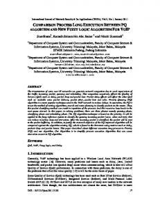
The cancel region pattern defines a set of activities (which may be located also in different branches). Activities which are in the process of execution within this area are aborted when the cancel region pattern is activated. Activities which are in the process of execution outside of this area stay unaffected. To implement this pattern with the WEE comes with some difficulties. The WEE cannot abort only parts of the execution. If the WEE receives the stop-signal from the controller, the workflow instance is stopped. Therefore, also activities which should stay in the process of execution are affected, which is not the intention of the pattern. Even if the handler wrapper does not allow the abortion, the result of the service call will not be integrated into the workflow by the WEE. The handler wrapper will not even be asked to provide the result value. But the WEE will ask for a passthrough value which gives the handler wrapper the possibility to store the result and reuse it when the workflow is continued. The sequence diagram in Fig. 1 now shows how the cancel region pattern can be implemented by the WEE. After the handler wrapper receives the stop call -signal, the service call is continued unaffected and the result of the service call is stored. The passthrough-value (identifying the result for later use) is returned to the controller of the workflow instance. When the controller continues the execution, the thread of control is set to the activities outside of the cancel region. The handler wrapper is provided with the passthrough-value and can look up the stored result. Therefore the service call does not have to be repeated (which may be costly). ŒŒ
Cancel Multiple Instance Activity. Multiple instances of an activity are executed within one workflow instance. The cancel multiple instance activity pattern aborts the workflow instance and subsequentially all active instances of an activity. Already completed instances of an activity are unaffected. The WEE covers this pattern with the same procedure as the cancel case pattern. The WEE allows to stop a workflow instance at any point during execution, therefore it is also possible to abort running instances of an activity.
×
Complete Multiple Instance Activity. Multiple instances of an activity are created. During the execution of the instances, the pattern indicates that the subsequent branch has to be executed. Therefore, remaining instances are no longer executed and withdrawn. Already finished instances are synchronized and their results are integrated into the workflow. The thread of control is passed to the subsequent branch. The WEE does not support this pattern. Although the WEE supports the manipulation of the thread of control, it is necessary to stop the execution before the manipulation can be done, which is not in the intention of the pattern.
3.6
Termination and Triggers
ŒŒ
Implicit Termination. A branch terminates if no further control structures have to be executed. If all branches have terminate, the workflow instance is also terminated and the workflow execution is marked as completed successfully. Due to the block structure of the WEE-DSL, the implicit termination is inherent.
ŒŒ
Explicit Termination. The workflow instance is terminated as soon as a specified point in the execution is reached. All remaining branches are canceled. The WEE allows the handler wrapper or the controller of the workflow to stop the execution at any point during the execution by sending the stop-signal. The same mechanism is provided to 14
Figure 1: Cancel Region Pattern the workflow description. Listing 17 shows an example implementation. The activity in line 1 sends the stop-signal to the WEE. If the handler wrapper has still running service calls, the handler wrapper is ordered to stop them if possible. Other activities will not be started. In contrast to the implicit termination, the end state of the workflow instance is set to stopped. LISTING 17: Explicit Termination 1 2 3 4 5 6
a c t i v i t y : stop , : m a n i p u l a t e do stop end a c t i v i t y : whatever , : m a n i p u l a t e do # w i l l n o t be e x e c u t e d end
Persistent & Transient Trigger. An activity is enabled by a trigger. The persistent ∗ trigger pattern is implemented if the trigger event is stored until the activity is scheduled ∗ for execution. The event enables the activity during any time in the workflow execution. The transient trigger enables an activity only when it is scheduled for execution. If the transient trigger event occurs before the activity is scheduled for execution, the event is withdrawn. An activity which has not been enabled by a trigger blocks the execution until a trigger event occurs or the workflow execution is canceled. The WEE does not support triggers directly. As the execution of a service call is delegated to the handler wrapper, the trigger logic can be placed there. The handler wrapper can block the execution until the trigger event occurs. The downside of this approach is that the triggering logic is not anymore in the workflow description.
3.7
Iterations
Arbitrary Cycles. The arbitrary cycles pattern allows unstructured loops. The thread ∗ 15
Figure 2: Arbitrary Cycles Pattern Example of control can be set back to a defined point in the workflow description. The defined point can be located within another arbitrary cycle. Fig. 2 shows an example of a of an arbitrary cycle. As the WEE-DSL has a block structure, the arbitrary cycles pattern can not be expressed directly. Instead, the WEE allows modification of the thread of control which can be used to simulate the behavior. Fig. 3 shows how a modified handler wrapper has to act to implement the pattern. Activity 1 and Activity 2 are performed normally as service calls. The next call service-message is then interpreted by the handler wrapper. The decision if the thread of control has to be altered is based on the condition provided by the workflow description. If the condition is validated as true, the thread of control is set to the given position identifier. The necessary information can therefore be specified in the workflow description and is not hard-wired in the handler wrapper. Although this implements the arbitrary cycles pattern, a complete implementation of the handler wrapper may also take care of possible side-effects which can arise when dealing with parallel active branches. ŒŒ
Structured Loop. An activity or a set of activities and control structures are executed repetitive. The loop can be top-controlled or bottom-controlled. In contrast to the arbitrary cycles pattern, a structured loop can be expressed in a block manner. The WEE-DSL directly supports the structured loop pattern with the cycle-element. This element implements the top-controlled loop. Bottom-controlled loops are not supported but can be expressed through a top-controlled loop with minor overhead. Listing 18 shows a sample of a structured loop. LISTING 18: Structured Loop 1 c o n t e x t : x => 3 2 c y c l e ( ”@x > 0 ” ) do 3 a c t i v i t y : countdown , : m a n i p u l a t e do 4 @x −= 1 5 end 6 end
∗
Recursion. The execution of an activity results in the execution of a new instance of the overall workflow description that is currently executed. Each recursion has to have at least one exit condition. As the WEE does not has the concept of multiple instances, the recursion cannot be supported directly. Instead, a recursion can be seen as a normal service call which in turn invokes a new workflow instance. The implementation can be therefore done by the handler wrapper.
3.8
Comparison to Other Engines
When we compare WEE with other workflow engines, the boundaries of our execution engine become apparent. Our execution engine focuses on the control flow aspect of workflows. 16
Figure 3: Arbitrary Cycles Pattern Implementation More precisely, we even focus on a single thread of control within our execution engine (except parallel branches). Existing workflow engines on the other hand have to cover a much larger set of functions and do not only focus on the control flow aspect. They also provide support for data and resource handling, security, logging, repair strategies and much more. Table 1 shows a summary of the pattern coverage as described so far.
Flow
Basic Control
Sequence
ŒŒ
Parallel Split
ŒŒ
Synchronization
ŒŒ
Exclusive Choice
ŒŒ
17
instances
orchestrated
handler/external
Pattern name
modified workflow
Pattern class
directly supported
Table 1: Workflow Patterns Coverage
Advances Branching and Synchronization
Simple Merge
ŒŒ
Multi-Choice
ŒŒ
Structured Synchronizing Merge
ŒŒ ×
Structured Discriminator
×
Blocking Discriminator
×
Cancelling Discriminator
ŒŒ
Structured Partial Join
×
Blocking Partial Join
×
Cancelling Partial Join
ŒŒ
Generalised AND-Join
×
Local Synchronizing Merge
×
General Synchronizing Merge
×
Thread Merge
ŒŒ
Thread Split
ŒŒ ∗
Synchronization Multiple Instances with a
ŒŒ
Priori Design-Time Knowledge Multiple Instances with a
ŒŒ
Priori Run-Time Knowledge Multiple Instances without
ŒŒ
a Priori Run-Time Knowledge Static Partial Join for
×
Multiple Instances Cancelling Partial Join for
ŒŒ
Multiple Instances Dynamic Partial Join for
×
Multiple Instances Œ
Deferred Choice State Based
18
instances
orchestrated
Multi-Merge
Multiple Instances without Multiple Instances
handler/external
Pattern name
modified workflow
directly supported
Pattern class
Interleaved Parallel Routing
Œ
Critical Section
ŒŒ
Interleaved Routing
ŒŒ
Cancel Task
ŒŒ
Cancellation
Cancel Case
ŒŒ
and Force
Cancel Region
Completion
Cancel Multiple Instance Activity
∗ ŒŒ ×
Complete Multiple Instance Activity ∗
Arbitrary Cycles ŒŒ
Structured Loop
∗
Recursion Termination
Trigger
instances
ŒŒ
Milestone
Iteration
orchestrated
handler/external
Pattern name
modified workflow
directly supported
Pattern class
Implicit Termination
ŒŒ
Explicit Termination
ŒŒ
Transient Trigger
∗
Persistent Trigger
∗
Wohed et al. [4] created a pattern based evaluation of different open source workflow systems. The analysis of our pattern support above allows to compare the coverage of our execution engine with this evaluation. In contrast to Wohed et al., we used a more detailed categorization with levels of support instead of just coverage. To allow a comparison, we assume that directly supported (ŒŒ) is equal to “+”, modified workflow (Œ) and handler/external (∗) are equal to “+/-” and orchestrated instances (×) refers to “-” as this is the least supported category. The results of the comparison (see Tab. 2) show that WEE, although minimal, covers a range of patterns that enables it to outperform several commercial solutions. We conclude therefore that converting workflow description languages to the WEE-DSL can be achieved with low effort. 19
Table 2: Support of Control Flow Patterns Product + +/-
4
WEE
22
10
11
StaffWare 10
14
0
29
WebSphere MQ 3.4
11
0
32
Oracle BPEL PM 10.12
18
6
19
JBoss jBPM 3.1.4.2
13
2
28
OpenWFE 1.7.3
20
4
19
Enhydra Shark 2.0
11
0
32
Conclusion
In this technical report we outlined the structure of our DSL as well as evaluated its the supplied vocabulary against existing patterns. Additionally we compared the results to existing products. We proved that our approach is well suited to serve as a bridging technology. We envision that WEE is the core of a new series of network based execution engines that take arbitrary workflow descriptions (transformed to the DSL) and execute it providing superior transparency. We envision external modules for monitoring, repair and semantic rule checking to become common network based infrastructure that is shared process aware information systems.
References [1] G. Stuermer, J. Mangler, and E. Schikuta, “A domain specific language and workflow execution engine to enable dynamic workflows,” in Parallel and Distributed Processing with Applications, International Symposium on, vol. 0, (Los Alamitos, CA, USA), pp. 653– 658, IEEE Computer Society, 2009. [2] G. Stuermer, J. Mangler, E. Schikuta, and C. Witzany, “Network based execution of dynamic workflows in grid and cloud based environments,” in Austrian Grid, National Symposium, (Linz, Austria), p. 1, OCG, Sept. 2009. [3] W. M. P. V. D. V. der Aalst, A. H. M. T. Hofstede, B. Kiepuszewski, and A. P. Barros, “Workflow patterns,” Distributed and Parallel Databases, vol. 14, no. 1, p. 5–51, 2003. [4] P. Wohed, N. Russell, A. H. M. ter Hofstede, B. Andersson, and W. M. P. van der Aalst, “Patterns-based evaluation of open source BPM systems: The cases of jBPM, OpenWFE, and enhydra shark,” tech. rep., BPM Center Report BPM-07-12, BPMcenter.org, 2007.
20