Nov 25, 2014 - inside and outside stratiform clouds, resulting in sensor fail- ure and no response to atmospheric change. These extremely dry relative humidity ...
Aug 9, 2016 - from 0 at the cloud base to a maximum at the cloud center, then decrease ...... call that the retrieval does not require any a priori knowl- edge or ...
May 23, 2014 - (one Lufthansa, the other China Airlines) show that more than 340 h of cloud data have been recorded at normal cruise altitudes (> 10 km) and ...
May 23, 2014 - measures the concentration and optical equivalent diameter of particles from 5 to 75µm. The backscatter cloud probe. (BCP) was designed as a ...
Supplement to Ground-based assessment of 14 limb and occultation ozone profile data records. 5. Altitude [km] lidar. 15. 20. 25. 30. 35. 40. 45. âα [%/dec].
For winter time at SNB, the seasonal derived start time window is with the least standard deviation, but doesn't exhibit the minimal value from the diurnal cycle.
Mad-LIP. Slope. Int. R2. 0.768(2). 0.06(2). 0.9998. 0.7917(5). 0.006(2) ..... CU Ground MAX-DOAS Instrument: lowering RMS noise and first measurements of.
For NMHC in air, KOS_A achieved no baseline resolution for methane, ethane, and. 140 .... reaction time of flight mass spectrometer, Int. J. Mass Spectrom., 247, 72-80, 2005. 263 ... National center for scientific research, Aubière Cedex (France) ..
Apr 1, 2015 - This autopilot allows precise measurement flights in the lower ABL ... side the CPCs were individually increased using software commands.
Munich Airport during the âLuFo iPort VISâ campaign fo- cusing on visibility forecast. ... offering auspicious conditions for automation and continu- ous updating.
Sep 20, 2012 - However, cloud droplet size measurements are subject to various ... on the set-up and wind conditions. ..... ner, personal communication, 2010).
Nov 15, 2012 - ferent PTR-MS configurations were calibrated at low ppbv mixing ratios ...... The US Geological Survey provided support while this manuscript.
Dec 4, 2012 - ment techniques. Total OH reactivity is measured by the CRM using a com- .... For field measurements it would be desirable to use a small, more ...... The service charges for this open access publication have been covered by ...
Nov 15, 2012 - 2Presently at the US Geological Survey, National Center, 12201 Sunrise Valley Dr. ... 4800 Calhoun Road, The University of Houston, Houston TX 77204, USA ...... Henry's law constants and axillary odour investigations, Int. J.
Feb 3, 2014 - 1Department of Mechanical Engineering, Colorado State University, Fort ... Received: 3 July 2013 â Published in Atmos. Meas. Tech. Discuss.
Jul 30, 2015 - all available ozone column satellite data sets, surface Brewer and Dobson ...... in the ozone data product, which correctly indicates large.
Feb 17, 2016 - the auto-conversion processes as well as the characteristics .... ical services and the scientific community, as well as to .... PSD parameters.
Jun 5, 2013 - Inc., Barrington, NJ, USA): one path passed through the ex- ternal Hg .... puScope 12100, GaGe, Lockport, Illinois, USA) is used to digitize the ...
Jan 10, 2014 - www.atmos-meas-tech.net/7/65/2014/ doi:10.5194/amt-7-65- ... ENSCI/Droplet Measurement Technologies; DMT) are ana- lyzed to quantify the ...
Nov 1, 2016 - mar et al., 2015; Snyder et al., 2013). Low-cost sensor de- ...... Zhu, K. N., Allen, T., and Smith, K. R.: A low-cost particle counter as a realtime ...
May 4, 2012 - the Deep Blue algorithm from the Sea-viewing Wide Field- of-view Sensor ... The implementation of MAPSS on the Web, online data access ...... hosting the MAPSS database and the Web MAPSS user interface. Lastly, our ...
SSI) using the KOPRA forward model and the KOPRA-fit retrieval scheme. ..... the measurement error covariance matrix, F represents the nonlinear forward .... NESR of 9.7 nW/(cm2 sr cmâ1) in the O3 spectral band and. 0.91 nW/(cm2 sr ...... Physics,
Jun 12, 2014 - mate power plant ramp rates and provide short-term solar irradiance forecasts. The cloud shadow speed sensor (CSS) is constructed using an ...
Cloud shadow speed sensor V. Fung, J. L. Bosch, S. W. Roberts, and J. Kleissl Department of Mechanical and Aerospace Engineering, University of California, San Diego, California, USA Correspondence to: J. Kleissl ([email protected]) Received: 13 June 2013 – Published in Atmos. Meas. Tech. Discuss.: 22 October 2013 Revised: 18 March 2014 – Accepted: 23 April 2014 – Published: 12 June 2014
Abstract. Changing cloud cover is a major source of solar radiation variability and poses challenges for the integration of solar energy. A compact and economical system is presented that measures cloud shadow motion vectors to estimate power plant ramp rates and provide short-term solar irradiance forecasts. The cloud shadow speed sensor (CSS) is constructed using an array of luminance sensors and a high-speed data acquisition system to resolve the progression of cloud passages across the sensor footprint. An embedded microcontroller acquires the sensor data and uses a crosscorrelation algorithm to determine cloud shadow motion vectors. The CSS was validated against an artificial shading test apparatus, an alternative method of cloud motion detection from ground-measured irradiance (linear cloud edge, LCE), and a UC San Diego sky imager (USI). The CSS detected artificial shadow directions and speeds to within 15◦ and 6 % accuracy, respectively. The CSS detected (real) cloud shadow directions and speeds with average weighted rootmean-square difference of 22◦ and 1.9 m s−1 when compared to USI and 33◦ and 1.5 m s−1 when compared to LCE results.
1 Introduction Given the impact of fossil fuel consumption on the environment, it is imperative that renewable energy sources provide a greater fraction of world energy demand. On average, the Earth receives 8000 times more solar energy than the energy consumed globally, making solar energy a strong candidate for supplying future world energy needs. However, difficulties in integrating variable generators into the electric grid have impacted the rate of large-scale adoption of solar power. The variability of the solar resource could be better accommodated by grid operators if fluctuations in irradiance caused by cloud cover could be predicted.
Understanding cloud motion is critical for ramp rate estimation and short-term forecasting (Arias-Castro et al., 2013; Coimbra et al., 2013; Lave et al., 2012, 2013), because cloud motion causes a sudden shortage or oversupply in solar power and must be compensated for with an opposing ramp of energy storage or conventional generation. Previous studies have used satellite imagery for estimating cloud motion (Leese et al., 1971; Hammer et al., 1999; Lorenz et al., 2004; Perez et al., 2010). However, due to satellite navigation, resolution, and parallax uncertainties, such cloud motion estimates are of limited use in very short-term, intra-hour forecasting. Other methods are based on ground measurements that can be used to yield cloud shadow speed. Cloud shadow motion vectors are typically equivalent to cloud motion vectors as measured from satellites or simulated through numerical weather prediction (since Sun–Earth distance cloud–Earth distance), but large solar zenith angles or large cloud vertical development relative to horizontal translation can introduce differences. While cloud shadow speed may not be as useful as horizontal cloud speed for meteorological models, cloud shadow motion vectors are more relevant for groundbased solar forecasting applications. For the remainder of the paper we will refer to “cloud speed” or “cloud motion vector” measurements for conciseness, although strictly cloud shadow motion vectors are measured. Examples of cloud speed detection from ground sensors are given in Hinkelman et al. (2011), who determined cloud speeds by analyzing the time lag in maximum cross correlation between two sensors aligned with the cloud direction, but the method cannot be automated since cloud direction has to be known a priori. Weigl et al. (2012) also derived velocity vectors from spatial irradiation data by considering rectangular clouds and tracking the movement of irradiation minima across the sensor array. Recently, two different approaches to determine cloud motion vectors were developed and validated by Bosch et
Published by Copernicus Publications on behalf of the European Geosciences Union.
1694
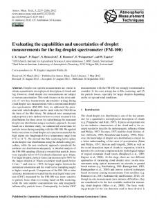
Figure 1. Idealized sketch showing the most correlated pair of signals shifted by tab (adapted from Bosch et al., 2013).
al. (2013) using ground-based solar radiation measurements. The first approach (further developed in Bosch and Kleissl, 2013) considers the kinematic equations of a linear cloud edge (LCE) passing through a sensor triplet and will be used in this paper for validation. The second method is based on the most correlated pair (MCP) of sensors arranged in 12 m diameter semi-circular array and lays the foundation of the cloud shadow speed sensor (CSS) described here. However, the limited sampling frequency requires sensor spacings of tens of meters and does not permit detecting cloud speeds with enough resolution to cover the full range of naturally occurring cloud speeds. Also, the system is not self-contained and cannot perform on-board post-processing. A semicircle system that is smaller, self-contained, and sampling at high frequency is required for commercial use, and is described in this paper. Section 2 describes the theoretical concept for the cloud motion vector (CMV) measurement. Sections 3.1 and 3.2 desribes the phototransistor characteristics, optical assembly, and layout. In Sect. 3.3 the data acquisition and postprocessing system is presented and quality control is discussed. Performance parameters and limitations of the CSS are explained in Sect. 3.4. Validation procedures for the algorithm and cloud motion results against artificial shadows and (real) clouds are described in Sects. 3.5 and 3.6, and results of the validation are shown in Sect. 4.
V. Fung et al.: Cloud shadow speed sensor
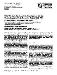
Figure 2. cloud shadow speed sensor (CSS). The entire system is contained inside a weather-proof enclosure. On the top of the enclosure is an array of nine phototransistors used to measure the variation in solar radiation as clouds passed overhead.
solar irradiance over the extent of the sensor array. Using the MCP method described in Bosch et al. (2013), the largest similarity in a pair of signals indicates alignment with the direction of cloud motion and is determined by the crosscorrelation coefficient Rab (1t): Rab (1t) = 1 Xn La,t (m) − L¯ a,t m=1 n−1 Lˆ a,t
Theory: most correlated pair method (MCP)
Variability of solar irradiance at the Earth’s surface is mainly due to cloud shadows with varying light intensity. We present here a system to obtain CMVs using an array of groundbased sensors to measure the spatiotemporal variation of Atmos. Meas. Tech., 7, 1693–1700, 2014
(1) !
Lb,t+1t (m) − L¯ b,t+1t Lˆ b,t+1t
where a and b are sensor indices, n is the number of sample points, t and t + 1t are the time and lagged time, La and Lb are solar irradiance time series, overbars indicate averages, and hats indicate standard deviations. Assuming sensors Sa and Sb are the pair with largest Rab , the detected solar irradiance time series will be most similar but delayed by a time lag, 1t = tab , as seen in Fig. 1. Determining the time lag via cross correlation, the cloud speed can be found by Vcloud =
D , tab
(2)
where D is the distance separating the sensors. 3
2
!
Cloud shadow speed sensor (CSS)
The CSS (Fig. 2) design objectives are compactness, fast data acquisition rates, robustness, and onboard processing. The implementation includes a high-performance microcontroller platform with built-in data acquisition and storage capability, and an array of phototransistors. The following subsections describe the system in more detail. www.atmos-meas-tech.net/7/1693/2014/
,
V. Fung et al.: Cloud shadow speed sensor
1695
Figure 3. Simplified schematic showing excitation voltage applied to the phototransistor collector, the 2 k load resistor, and the sensor output as applied to an analog input channel on the microcontroller.
3.1 Luminance sensors Solar radiation sensors consist of an array of nine phototransistors (TEPT4400, Vishay Intertechnology Inc., USA). The sensors have a spectral response ranging from approximately 350 to 1000 nm with a peak response at 570 nm. The manufacturer has characterized the sensors over an operating temperature range of −40 to +85 ◦ C. Response time was determined experimentally in our laboratory and found to be 21 µs rise time (10–90 % response). Excitation voltage for the sensors was 3.3 VDC supplied from a voltage regulator (LM2937-3.3, Texas Instruments Inc., USA) and applied to the phototransistor collector (Fig. 3). A 2 k load resistor was connected from the sensor emitter to system ground. The sensor outputs were taken at the emitter–load-resistor junction and fed to the analog input channels on the microcontroller. 3.2
Luminance sensor array
CMVs were determined with the phototransistors configured as an array of eight sensors positioned around a central sensor on a circle of radius 0.297 m, covering 0–105◦ in 15◦ increments (Figs. 2 and 4). Cross-correlation coefficients were computed for each pair of sensors (central sensor and a sensor on the circle) to determine cloud speed and direction based on Eqs. (1)–(2). Each sensor was placed at the base of and inside a black opaque tube with a diameter of 6.35 mm and height of 14.3 mm with a translucent acrylic light diffuser/collector at the top. The tube height was chosen such that the diffuser positioned above the sensor fully occupies the TEPT4400 field of view (FOV) as shown in Fig. 5. Full exposure of the TEPT4400 sensor FOV to the overhead light field dictates a vertical separation of h < 5.51 mm, but h = 2.78 mm was chosen in the design such that a tilt error of up to 18.8◦ would still allow the TEPT4400 FOV to remain within the diffuser area. This sensor optical assembly (TEPT4400, tube, www.atmos-meas-tech.net/7/1693/2014/
Figure 4. Sensor arrangement. Each circle represents a sensor arranged in a circular pattern with 15◦ radial spacing about the central sensor. Additional angles from 120 to 165◦ are obtained through equilateral triangles constructed from existing sensor positions. For example, for triangle abc the line from b to c results in an angle of 120◦ .
Figure 5. Cross-sectional view of luminance sensor optical assembly (TEPT4400, opaque tube, and light collector/diffuser) for a vertical spacing h that matches the TEPT4400 field of view (FOV) to the diffuser diameter. To reduce the effect of TEPT4400 sensor tilt errors, h = 2.98 mm was chosen instead.
diffuser) ensures that the CSS has a near-cosine response over the full −90 to 90◦ exposure to radiation from the fullsky hemisphere. When tested under halogen lights the diffuser was determined to have no effect on the incident light spectrum within the spectral response range of the sensor. 3.3
Data acquisition and post-processing
The microcontroller-based data acquisition system and sensors are powered by a small rechargeable 12 VDC sealed lead–acid battery. Regulated voltages (5 VDC for the microcontroller, 3.3 VDC for the sensors) are derived from the battery using integrated circuit voltage regulators (Fig. 3). The data acquisition system was configured using a Atmos. Meas. Tech., 7, 1693–1700, 2014
1696 high-performance 32 MIPS, 32 bit microcontroller platform (chipKIT Max32, Digilent Inc., USA) running at 80 MHz. The onboard static memory allows fast storage of up to 6000 10 bit data points per sensor. With our sampling rate of 667 samples s−1 , 6000 data points can be acquired and stored in approximately 9 s. A compromise had to be made between measurement precision and detectable irradiance range due to the limited 10 bit analog-to-digital converter (ADC) of the microprocessor. Hence, the TEPT4400 sensor circuit was deliberately designed to report voltages that exceed the measurement range of the microcontroller near solar noon on clear days. In particular, the detected solar irradiance saturates at 880 W m−2 but higher irradiance can be neglected since clear-sky periods rejected for post-processing due to small variance. Irradiance measurements under 880 W m−2 representing cloudy conditions are therefore better resolved and are more appropriate for CSS applications. The 6000 × 9 data array can be transferred to an off-board microSD card in 14 s, for archiving and further analysis. Alternatively, onboard post-processing is available and the results can then be relayed to a central computer via ethernet or wireless communication. The cloud speed and direction are computed using an algorithm based on Eqs. (1)–(2). Computing the cross-correlation for every time step (i.e., m = 1 to 5600 in 400 steps) would require 18 min. Optimization reduced the processing time to approximately 2 min. First, assuming a monotonous “smooth” signal, the cross-correlation time shift is performed in increments of 5 time steps instead of the standard 1 time step. Then, the temporary maximum Rab is located and the surrounding 10 Rab are computed in time steps of 1 to determine the exact tab the maximum Rab . Second, L¯ b and Lˆ b of each Rab are updated based on the previous L¯ b and Lˆ b . Through extensive post-processing analysis this algorithm has proven to be robust in finding tab . Quality control (QC) during post-analysis is required to increase the robustness of the algorithm (Bosch et al., 2013). Most importantly, periods of small variability in the signal (for example during clear conditions) or small correlation coefficients are excluded. In specific, the range in a set of measurements must exceed 7 % of the full-scale 10 bit reading and the largest Rab computed must be greater than 0.95. Both threshold values were determined empirically, and they ensure that data are only processed if a cloud passage occurred that results in a large signal-to-noise ratio and is more likely to produce correct CMVs. Measurements with several identical maximum Rab across different sensor pairs or unphysical cloud speeds (greater than 50 m s−1 is very unlikely) are also discarded. Lastly, a moving median filter is computed at every CMV timestamp to determine the central tendency of QC results within the past 30 min. While there is a potential to delay the detection of a change in cloud motion, CMVs generally change over longer timescales. In addition to CMV detection, variability in solar irradiance can be measured by the CSS and could be used by grid Atmos. Meas. Tech., 7, 1693–1700, 2014
V. Fung et al.: Cloud shadow speed sensor operators to inform control schemes for energy storage or rampable generation throughout the day. 3.4
Performance parameters and limitations
Based on typical cloud speeds obtained over the US (Bosch and Kleissl, 2013; Lave and Kleissl, 2013), the CSS was designed to detect cloud speeds of up to 15 m s−1 with at least 1 m s−1 resolution. The resolution of detectable cloud speeds is determined by the radius of the semicircle (D = 0.297 m, Eq. 2) and the sampling time step (1t = 0.0015 s). For the CSS design, the resolvable cloud speeds are given by ND1t , where N = 1, . . . , k and k defines the maximum number of time shifts used in the cross-correlation computations. In this case we select the minimum cloud speed as 1 m s−1 , which yields k = 200. Cloud speeds of less than 1 m s−1 are unusual and have little relevance to solar power as the resulting ramp rates would be slow and approach the cloud lifetime (Jiang et al., 2006). With 6000 samples from each sensor, the central 5600 data points are shifted in the cross correlation procedure, leaving k = 200 bidirectional time shifts to determine tab . The direction of the shift that produces the maximum Rab indicates whether the clouds are moving in one direction or the opposite. The largest and smallest resolv0.297 m D −1 = 0.0015 able cloud speeds are therefore 1t s = 198.1 m s 0.297 m D and k1t = 200·0.0015 s = 0.99 m s−1 , respectively. The cloud speed resolution scales with N1 such that very large cloud speeds are obtained at poor resolution (for example the sec0.297 m −1 ond largest speed is 2·0.0005 s = 99.1 m s ), while smaller cloud speeds can be detected at higher resolution. 3.5
Validation using artificial shadows
Prior to measuring complex ground radiation patterns caused by clouds, a performance test with a simple shadow of known relative velocity was used to validate the CSS. Under clear conditions at solar noon, an irregular stationary shadow was created from a suspended object. The CSS was mounted on a mobile platform that was pulled at a constant speed by a torque motor. Relative velocity vectors between the shadow and sensor can be determined by the motor rotational speed and orientation of the sensor. The magnitude of the irradiance reduction (i.e., the signal for Eq. 1) in the shadow decreases with increasing height of the object because of increased diffuse irradiance. Consequently, the CSS was first tested with a dark shadow from an object positioned 0.23 m above the CSS. The CSS was moved at a known CSS speed of 0.51 m s−1 with different directions (60 and 90◦ ). Since the known CSS speed did not fall within the range of detectable cloud speeds (see Sect. 3.4), k = 600 was used to reduce the smallest resolvable cloud speed to 0.33 m s−1 for this experiment. The procedure was repeated with the object raised to 1.35 m above the CSS to observe how the influence of increased diffuse irradiance affects the measurements, post-processing, and CMVs. www.atmos-meas-tech.net/7/1693/2014/
V. Fung et al.: Cloud shadow speed sensor
1697
Table 1. CSS performance for the artificial cloud shadow experiment. CSS direction [◦ ]
True speed [m s−1 ]
CSS speed [m s−1 ]
60 90 60 270
60 105 60 270
0.51 0.51 0.51 0.51
0.48 0.48 0.48 0.48
For all conditions, the detected directions were correctly identified and the detected shadow speed fell within 6 % of the true speed (Table 1), which is acceptable for CSS application. The only direction error occurred in experiment 2, but the maximum Rab values for the 90 and 105◦ directions were essentially indistinguishable with a difference of 0.0006. These results validate the basic concept, realization, and algorithm of the CSS to measure (real) cloud speed and direction. 3.6
Deployment and validation against two cloud motion sensors
The CSS was deployed on 9 days over a period of 6 months from March to August 2013 at the UC San Diego solar energy test bed in La Jolla, CA (Table 2). For validation, a sky imager was deployed adjacent to the CSS and a consistent coordinate system was established. The UCSD sky imager (USI – Chow et al., 2011; Urquhart et al., 2013; Yang et al., 2014) captures images using an upward-facing charge-coupled device (CCD) image sensor that senses RGB channels at 12 bit precision and 1748 × 1748 pixel resolution. A 4.5 mm circular fisheye lens allows for imaging of the entire sky hemisphere. Utilizing composite high dynamic range (HDR) imaging, the USI outputs images at 16 bit with a dynamic range of 84 dB. The images used in this analysis were taken by a rooftop-mounted USI located at 32.8722◦ N, 117.2410◦ W, and 129 m m.s.l. capturing images every 30 s. A cross-correlation method is applied to derive a representative cloud vector for the image (Yang et al., 2013). USI cloud directions are expected to be accurate, but cloud speeds scale linearly with cloud height, which is difficult to determine. Therefore the LCE approach (see Introduction and Bosch et al., 2013; Bosch and Kleissl, 2013) was applied to three photodiode pyranometers (Li-200SZ, Licor Inc.). The pyranometers were colocated on the USI rooftop and setup in an orthogonal coordinate system with average separation of 7 m and logged to a single CR1000 (Campbell Scientific Inc.) data logger with an acquisition frequency of 20 Hz.
www.atmos-meas-tech.net/7/1693/2014/
1000
central sensor
500
Direction
0.23 m 0.23 m 1.35 m 1.35 m
Solar Irradiance [W m−2 ]
True direction [◦ ]
0 12
13
14
15
16
17
E
18 CSS LCE USI
N W S E 12
Speed [m s−1 ]
Height of object above CSS
13
14
13
14
15
16
17
18
15
16
17
18
10
5
0 12
PST [h]
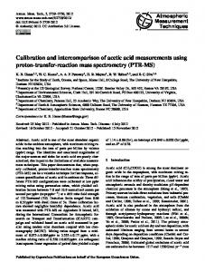
Figure 6. Solar irradiance and CMVs from CSS, USI, and LCE for 23 July. Luminance measurements of the central TEPT4400 sensor were calibrated against a colocated pyranometer to obtain W m−2 of solar irradiance.
4
Results and discussion
The predominant cloud conditions in coastal southern California are overcast stratocumulus and few to scattered cumulus clouds. Table 2 shows the average cloud directions and speeds on the nine deployment days. Table 3 presents the corresponding root-mean-square difference (RMSD) and mean bias (MB). The 23 July and 8 August deployments are selected for discussion in greater detail. The KNKX METAR station 9 km to the east reported the following conditions: the air temperature during the 23 July and 8 August deployments was 22– 26 ◦ C and 24–25 ◦ C, respectively. Surface winds were 260 to 310◦ at 4.1 to 5.7 m s−1 on 23 July and 250 to 280◦ at 3.6 to 4.6 m s−1 on 8 August. There were few clouds at 400 m below scattered clouds at 900 to 1200 m a.g.l. on 23 July and few clouds at 460 m a.g.l. on 8 August. The solar irradiance and resultant CMVs for 23 July and 8 August are shown in Figs. 6 and 7. For 23 July, 20 % of the 1611 raw results satisfy the QC criteria described in Sect. 3.3; most results are excluded since the variability did not exceed 7 % of 10 bit full-scale reading, as observed after 14:00 PST. Sky imagery reveals that CMV results occurred in scattered stratocumulus cloud cover during 12:00–14:00 PST that became overcast after 14:00 PST (differences to the METAR cloud observations can be explained by large spatial heterogeneity of cloud cover in this coastal Atmos. Meas. Tech., 7, 1693–1700, 2014
1698
V. Fung et al.: Cloud shadow speed sensor
Table 2. Deployment dates and average direction and speed for each cloud motion sensor. USI CMVs are unavailable for 14 March and 10 May due to incorrect cloud heights. LCE results are removed on 23 April due to an insufficient amount of results that passed QC. Deployment [PST]
Average direction [◦ ]
Average speed [m s−1 ]
Date in 2013
All methods
CSS
LCE
USI
CSS
LCE
USI
14 March 16 March 23 April 10 May 14 May 3 June 23 July 7 August 8 August
Table 3. RMSD and MB of CSS results compared to LCE and USI. Due to incorrect cloud height observed, no cloud motion results were detected from USI on 14 March and 10 May. LCE results are excluded for 23 April due to a shortage of results that pass QC. RMSD Direction [◦ ]
Speed [m s−1 ]
Direction [◦ ]
Speed [m s−1 ]
LCE
USI
LCE
USI
LCE
USI
LCE
USI
14 March 16 March 23 April 10 May 14 May 3 June 23 July 7 August 8 August
41 25 – 38 24 20 35 41 37
– 24 20 – 20 26 14 7 26
3.0 0.9 – 1.5 0.9 0.6 1.2 1.4 1.3
– 1.3 0.6 – 2.5 2.4 1.2 2.1 0.9
8 −8 – 31 13 −15 25 −18 13
– −8 −13 – 1 −22 14 2 13
-0.7 0.9 – −0.6 0.4 −0.2 −0.4 −1.0 0.4
– −0.9 0.1 – −0.4 2.2 0.9 −0.2 −0.2
All
33
22
1.5
1.9
9
−0.7
−0.1
0.2
Date in 2013
1000
central sensor
500
0 10
11
12
13
14
15
16
17
E
Direction
−2
Solar Irradiance [W m ]
MB
N W S E 10
−1
Speed [m s ]
18 CSS LCE USI
11
12
13
11
12
13
14
15
16
17
18
14
15
16
17
18
8 6 4 2 0 10
PST [h]
Figure 7. Solar irradiance and CMVs detected during the CSS deployment on 8 August 2013.
area). Overcast conditions cause insufficient solar variability to pass the QC criteria, but the 30 min median filter causes CMV to persist into the overcast period, like during 14:00– 14:30 PST. The CSS QC directions indicate cloud movement Atmos. Meas. Tech., 7, 1693–1700, 2014
from the west-northwest (WNW, 300◦ ) direction, consistent with surface winds and visual inspection of sky imagery. USI and LCE results show an average cloud motion direction of 286 and 275◦ with RMSDs of 14 and 35◦ , respectively. The CSS cloud speed ranges from 3.0 to 6.0 m s−1 . USI and LCE yield an average cloud speed of 3.9 and 5.3 m s−1 , with RMSD of 1.2 and 1.2 m s−1 compared to CSS results, respectively. On 8 August, visual inspection from sky imagery shows thin, scattered stratocumulus clouds during 10:30–14:45 PST from WNW that became more widespread during 14:45– 16:30 PST. Overcast conditions occurred after 16:30 PST, which causes low solar irradiance variability and again produces no CMV results. The CSS detects average cloud movement from the WNW (299◦ ) direction, while USI and LCE detect average cloud directions of 286 and 283◦ , respectively. RMSD values for comparing CSS to USI and LCE direction results are 26 and 33◦ , respectively. The CSS cloud speed increases from 2.0 to 6.8 m s−1 throughout the deployment and is consistent with the ranges and trends observed by USI www.atmos-meas-tech.net/7/1693/2014/
V. Fung et al.: Cloud shadow speed sensor and LCE with RMSD of 0.9 and 1.3 m s−1 , respectively. It is worth noting that all speed results are similar during periods of high solar variability (14:45–16:00 PST), which indicates more robustness during favorable cloud conditions. Although the three methods slightly differ in both detected direction and speed, the results lie within the range of CSS, USI, and LCE method uncertainty. True cloud speeds are not available and it is therefore unclear which sensor is more accurate. The post-analysis conducted on days presented in Tables 2 and 3 assumes a single layer of cloud movement. In the presence of multilayer clouds, several regions with high density of CMVs can be found at different cloud velocities. By using a histogram peak-finding technique on CMV results, the CSS can determine multilayer cloud movement. This method was based on prior research on CMV determination from ground irradiance data and requires further analysis, but should be feasible to implement in the CSS algorithm for identifying multilayer CMVs. Cloud motion experiencing wind shear can have a vertical speed component that is undetectable by the CSS. However, the CSS will detect 2-D cloud shadow motion (x–y plane) in scenarios with 3-D cloud movement. While this measurement may not be as useful for meteorological models, the cloud shadow speed is more relevant to provide for solar variability and forecasting applications. The analysis presented in Tables 2 and 3 also shows comparable results between CSS, USI, and LCE results for a wide range of cloud directions (southeasterly to northwesterly). The range of cloud speeds is more limited due to the low cloud heights and benign weather conditions in coastal southern California, but results are again consistent with the other methods. Overall speed and direction biases are essentially zero and typical RMSDs are 2 m s−1 and 30◦ .
5
Conclusions
Nine phototransistors arranged in a semicircular formation were used to obtain cloud shadow motion vectors by finding the maximum signal cross correlation between the different pairs of sensors. Fast sampling rates by the microprocessor allowed the system to be compact yet able to detect the full range of typical cloud speeds from 1 to 15 m s−1 (with 1 m s−1 precision) and up to 24 m s−1 with 2 m s−1 precision. The CSS was validated using an artificial shading test apparatus and was found to detect cloud directions and speeds to within 15◦ and 6 % accuracy, respectively. Nine deployments on partly cloudy days resulted in cloud directions and speeds consistent with those observed from a sky imager and computed from the LCE method. Unlike the prior proof of feasibility in Bosch et al. (2013), the present CSS system is self-contained and more economical while still producing accurate cloud motion vectors. With the present QC criteria, the CSS does not provide CMV results under uniform overcast conditions, but the small solar irradiance variability in overcast conditions does not present www.atmos-meas-tech.net/7/1693/2014/
1699 a major issue for solar power integration. Further optimization of the algorithm will refine QC procedures to retain as many CMVs as possible while ensuring robustness of the results.
Acknowledgements. This work was supported by the California Energy Commission Energy Innovations Small Grant (EISG) and the California Public Utilities Commission California Solar Initiative RD&D programs. We are grateful to Tyler L. Capps, Andy Chen, and Jeff Head for assisting with hardware and software development; Nick Busan for providing access to the experimental facility; and (iii) Ben Kurtz, Andu Nguyen, Bryan Urquhart, and Elliot Dahlin for constructing and operating the UCSD sky imager. Edited by: S. Malinowski
References Arias-Castro, E., Kleissl, J., Lave, M., Schweinsberg, J., and Williams, R.: A Poisson model for anisotropic solar ramp rate correlations, Sol. Energy, 101, 192–202, 2014. Bosch, J. L. and Kleissl, J.: Cloud motion vectors from a network of ground sensors in a solar power plant, Sol. Energy, 95, 13–20, 2013. Bosch, J. L., Zheng, Y., and Kleissl, J.: Cloud velocity estimation from an array of solar radiation measurements, Sol. Energy, 87, 196–203, doi:10.1016/j.solener.2012.10.020, 2013. Chow, C. W., Urquhart, B., Kleissl, J., Lave, M., Dominguez, A., Shields, J., and Washom, B.: Intra-hour forecasting with a total sky imager at the UC San Diego Sol. Energy testbed, Sol. Energy, 85, 2881–2893, doi:10.1016/j.solener.2011.08.025, 2011. Coimbra, C., Kleissl, J., and Marquez, R.: Overview of solar forecasting methods and a metric for accuracy evaluation, in: Solar Resource Assessment and Forecasting, edited by: Kleissl, J., Elsevier, Waltham, Massachusetts, 2013. Hammer, A., Heinemann, D., Lorenz, E., and Lückehe, B.: Shortterm forecasting of solar radiation: a statistical approach using satellite data, Sol. Energy, 67, 139–150, 1999. Hinkelman, L., George, R., Wilcox, S., and Sengupta, M.: Spatial and temporal variability of incoming solar irradiance at a measurement site in Hawaii, in: 91st American Meteorological Society Annual Meeting, 23–27 January 2011, Seattle, WA, United States, 2011. Jiang, H., Xue, H., Teller, A., Feingold, G., and Levin, Z.: Aerosol effects on the lifetime of shallow cumulus, Geophys. Res. Lett., 33, L14806, doi:10.1029/2006GL026024, 2006. Lave, M. and Kleissl, J.: Cloud speed impact on solar variability scaling – application to the wavelet variability model, Sol. Energy, 91, 11–21, doi:10.1016/j.solener.2013.01.023, 2013. Lave, M., Kleissl, J., and Stein, J.: A Wavelet-based Variability Model (WVM) for solar PV powerplants, IEEE Transactions on Sustainable Energy, 99, 501–509, doi:10.1109/TSTE.2012.2205716, 2012. Lave, M., Stein, J., and Kleissl, J.: Quantifying and simulating solar power plant variability using irradiance data, in: Solar Resource Assessment and Forecasting, edited by: Kleissl, J., Elsevier, Waltham, Massachusetts, 2013.
Atmos. Meas. Tech., 7, 1693–1700, 2014
1700 Leese, J. A., Novak, C. S., and Clark, B. B.: An automated technique for obtaining cloud motion from geosynchronous satellite data using cross correlation, J. Appl. Meteorol., 10, 118–132, 1971. Lorenz, E., Hammer, A., and Heinemann, D.: Short term forecasting of solar radiation based on satellite data, in: Proceedings of the ISES Europe Solar Congress EUROSUN2004, Freiburg, Germany, 20–24 June, 2004. Perez, R., Kivalov, S., Schlemmer, J., Hemker Jr., K., Renné, D., and Hoff, T. E.: Validation of short and medium term operational solar radiation forecasts in the US, Sol. Energy, 84, 2161–2172, 2010. Urquhart, B., Ghonima, M., Nguyen, D., Kurtz, B., Chow, C. W., and Kleissl, J.: Sky imaging systems for short-term forecasting, in: Solar Forecasting and Resource Assessment, edited by: Kleissl, J., Elsevier, Waltham, Massachusetts, 2013.
Atmos. Meas. Tech., 7, 1693–1700, 2014
V. Fung et al.: Cloud shadow speed sensor Weigl, T., Nagl, L., Weizenbeck, J., Zehner, M., Augel, M., Öchsner, P., Giesler, B., Becker, G., Mayer, O., Betts, T., and Gottschalg, R.: Modelling and validation of spatial irradiance characteristics for localised irradiance fluctuations and enhancements, in: 27th European Photovoltaic Sol. Energy Conference, 24–28 September, Frankfurt, Germany, 3801–3804, 2012. Yang, H., Chow, C. W., Ghonima, M., Kurtz, B., Nguyen, D., Urquhart, B., and Kleissl, J.: Solar irradiance forecasting using a ground-based sky imager developed at UC San Diego, Sol. Energy, 103, 502–524, 2014.