Cluster-based Channel Assignment in Multi-radio Multi-channel Wireless Mesh Networks Anjum Naveed
Salil S. Kanhere
School of Electrical Engineering and Computer Science National University of Sciences and Technology Pakistan
[email protected]
School of Computer Science and Engineering University of New South Wales Australia
[email protected]
Abstract—In a typical Wireless Mesh Network (WMN), the interfering links can broadly be classified as coordinated and non-coordinated links, depending upon the geometric relationship. It is known that compared to coordinated interference, the non-coordinated interference result in significantly lower throughput and an unfair capacity distribution amongst the links. However, identification of non-coordinated interference relationships requires that each node is aware of the precise location of its neighbours, which is impractical. In this paper, we propose a novel two-phase Cluster-Based Channel Assignment Scheme (CCAS) that minimizes both non-coordinated as well as coordinated interference without requiring the nodes to be aware of the location of its neighbours. CCAS logically partitions the network into non-overlapping clusters. The links within each cluster operate on a common channel which is orthogonal to that used in neighbouring clusters, thus eliminating non-coordinated interference. The inter-cluster links are assigned channels such that any non-coordinated interference that they introduce is minimized. The second phase of CCAS minimizes the coordinated interference by exploiting the channel diversity to sub-divide each cluster into multiple interference domains, thereby increasing the capacity of individual links. Simulation-based evaluations demonstrate that CCAS can achieve twice the aggregate network goodput as compared to existing channel assignment schemes, while ensuring a fair distribution of capacity amongst the links.
I. I NTRODUCTION
In a typical Wireless Mesh Network (WMN), co-located links frequently interfere with each other, thus reducing the channel utilization. To improve the network capacity, WMN nodes are equipped with multiple radios (NICs). This enables interfering links to be active simultaneously, each operating on an orthogonal frequency channel. However, given the limited number of orthogonal channels in the radio spectrum (3 in IEEE 802.11b and 12 in IEEE 802.11a/g), efficient channel assignment scheme is required to minimize the interference. In order to identify the interfering links, existing channel assignment schemes rely on one of the three popular interference models:(i) Protocol model [1], (ii) Physical model [1] and (iii) Extended protocol model [2]. It is well known that the behavior of CSMA/CA protocol does not comply with both protocol and physical interference models [3]. The extended protocol model can correctly identify all single-hop interfering links. The channel assignment schemes that rely on this model assume that all interfering
links induce the same level of interference on the target link. However, Garetto et al. [4] have shown that this assumption is not true in practice. The authors have broadly classified the interfering links as coordinated and non-coordinated, depending on the geometric relationship between the interfering link and the target link. For a directional link l(i, j) – i being transmitter and j is the receiver – the directional link l′ (i′ , j ′ ) is a coordinated interfering link if the euclidean distance d(i, i′ ) is less than the carrier sensing range (RCS ). On the other hand, link l′ (i′ , j ′ ) is a non-coordinated interfering link if d(i, i′ ) > RCS and {d(i, j ′ ) and/or d(i′ , j) and/or d(j, j ′ )} ≤ RCS . Garetto et al. [4] have shown that noncoordinated interference results in significantly higher transmission losses and unfair capacity distribution amongst the links, as compared to coordinated interference. To the best of our knowledge, this observation has not been used in making channel assignment decisions. In this paper, we first compare the coordinated and noncoordinated interference under CSMA/CA protocol using an empirical example (Section II). We highlight the fact that compared to coordinated interference, non-coordinated interference has a severe impact on the channel utilization and consequently on the network capacity. This leads us to hypothesize that a channel assignment scheme, which prioritizes the minimization of non-coordinated interference over coordinated interference can significantly improve the network capacity. A simple empirical example is presented to demonstrate the merit of this approach. We formulate channel assignment as a two phase minimization problem where the minimization of non-coordinated interference is prioritized over the coordinated interference. We prove that this problem is NP Hard (Section III). As a solution to the problem, we propose a static distributed heuristic referred as Cluster-based Channel Assignment Scheme (CCAS) (Section IV). CCAS logically partitions the network into non-overlapping clusters, each comprising of nodes located within a carrier sensing range. All nodes within the cluster can communicate with each other over a common channel. Neighbouring clusters use orthogonal channels thus minimizing non-coordinated interference. The cluster-based approach of CCAS significantly reduces the complexity of minimizing non-coordinated inter-
ference as explained in Section IV-A. Inter-cluster connectivity is established by assigning the channels to all inter-cluster links such that minimal level of non-coordinated interference is introduced. Although cluster-based approach minimizes the noncoordinated interference, almost all links in WMN experience high level of coordinated interference, which limits the achievable throughput of the links in WMN. To minimize the coordinated interference, CCAS utilizes the orthogonal channels that have not been utilized for non-coordinated interference minimization. Such channels are assigned to intra-cluster links to break the domain of interfering links encompassing the entire cluster into multiple sub-domains while ensuring that this channel assignment does not introduce additional noncoordinated interference. We evaluate CCAS by comparing it with existing channel assignment schemes through simulations (Section V). The evaluation results demonstrate that CCAS can achieve twice the aggregate goodput as compared to existing schemes and ensures fair capacity distribution amongst links. II. M OTIVATION In this section, we first present a simple empirical example that demonstrates the impact of coordinated and noncoordinated interference on the link and network capacity. The subsequent example demonstrates the effectiveness of assigning channels with the primary goal of minimizing noncoordinated interference. Qualnet simulator was used for conducting the experiments. A. Coordinated vs. Non-coordinated Interference EXAMPLE 1: Consider three wireless links AB, CD and EF as shown in Figure 1(a). The nodes are equipped with IEEE802.11b radios, which transmit at a data rate of 11M bps. All radios are tuned to a common channel. The links are directional with a CBR traffic source (packet size 512) transmitting in saturation mode (i.e. transmitter always has a packet to send) in the direction of the marked arrows. The links in Figure 1(a) are placed in such a way that interference between them is coordinated. The value depicted against each link is the achievable goodput at network layer. In this scenario, the goodput of all links is equal (≈ 1M bps) with an aggregate capacity of 3M bps. We conducted additional experiments where the the number of coordinated interfering links was increased. We observed that the aggregate goodput remained the same (3M bps), while the capacity of the individual links decreased exponentially (results excluded for brevity). However, all links always received a fair share of the network capacity. Next, we simulated a scenario where the same three links were placed in such a way that they shared a non-coordinated relationship with each other, as shown in Figure 1(b). The aggregate goodput in this case reduced to 2.38M bps. Moreover, the three interfering links did not receive an equal share of the network capacity (AB = 0.47M bps, CD = 1.2M bps, EF = 0.71M bps). We observed that increasing the number of non-coordinated interfering links within the interference domain, decreased the aggregate goodput. Further, the individual links always received an unequal share of the network capacity
A 0.99Mbps B
0.47Mbps
D 0.99Mbps C
A
B E 1.2Mbps
(a) Coordinated links
A
B
A
Fig. 2. ence.
195k(1) C
481k(1) B
344k(1) A
F
(b) non-coordinated links
359k(1)
415k(1)
(c)
D
Impact of coordinated and non-coordinated interference on goodput 20.6k(1)
(b)
C NH
Rcs
(a)
0.71Mbps
IA
E 1.0Mbps F
Fig. 1.
FH
B
D
E
D 532k(1)
C
0.7k(1) 165k(1) F
215k(1) G
775k(1)
H
I
70k(2) 15.4k(2) 265k(2) 335k(1) 689k(2) 450k(1)
C 304k(1)
363k(1)
E 338k(2)
D
343k(2) E
F G H I 501k(2) 359k(1) 789k(1) F
G
H
I
Example illustrating impact of prioritizing non-coordinated interfer-
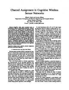
(results excluded). The following observations can be made from the results of the experiments. (i) Coordinated interfering links synchronise their transmissions when random-access MAC protocols such as CSMA are employed. As a result, packet collisions are reduced, resulting in near optimal channel utilization. The capacity of individual links exponentially decreases with the increase in number of interfering links. (ii) Non-coordinated links fail to coordinate their transmissions [4], resulting in sub-optimal channel utilization and unfair distribution of channel capacity amongst interfering links. The links, which experience significantly lower goodput (i.e. link AB in Figure 1(b)) are likely to form bottlenecks in the network, thus affecting the end-to-end throughput of multi-hop flows. The above example suggests that the network capacity can be improved if non-coordinated interference is minimized by channel assignment. B. Channel Assignment and Non-coordinated Interference The existing channel assignment schemes use the following metrics to quantify the impact of interference: the number of interfering links [2], [5], [6], the traffic load [6]–[9] or the channel utilization [9], [10]. However, these metrics do not necessarily capture the impact of non-coordinated interference. The following example demonstrates the effectiveness of assigning channels with the goal of prioritizing the minimization of non-coordinated interference over coordinated interference. Example 2: Consider the chain topology in Figure 2a where all links are operating on a common channel. The aggregate goodput achieved is 2.09M bps. Now assume that two channels are available. In Figure 2b we assign the channels using the metrics proposed in existing channel assignment schemes [2], [6]–[8]. Note that, in this particular example, all of the aforementioned metrics result in identical channel assignment. The aggregate goodput achieved in this case is 2.71M bps. Figure 2c illustrates the goodput achieved when the channels are assigned such that the non-coordinated links operate on orthogonal channels. The aggregate goodput in this case is 3.51M bps, which is significantly higher than that in Figure 2b. Furthermore, it is evident that no link is significantly
disadvantaged. This simple example demonstrates that the notion of assigning channels with the aim of reducing noncoordinated interference has merit. III. P ROBLEM F ORMULATION In this section, we first enlist the assumptions made for channel assignment (Section III-A). We then explain the notations used throughout the rest of the paper (Section III-B). Subsequently, we formulate channel assignment as a two phase minimization problem where minimization of non-coordinated interference is prioritized over coordinated interference and prove that this problem is NP Hard (Section III-C). A. Assumptions 1) All nodes are equipped with multiple wireless interfaces (i.e., interfaces per node ≥ 3). Each node can have different number of interfaces. Let n(v) be the number of interfaces of node v. 2) All WMN links are assumed to be operating in saturated mode. Therefore no data traffic constraints are considered for channel assignment. 3) The transmission range (RT ) and carrier sensing range (RCS ) of WMN nodes is fixed and all nodes transmit with the same transmission power. We assume that RCS = 2 ∗ RT . B. Notations Let directed graph G(V, E) represent the WMN, V being the set of nodes and E being the set of edges where an edge exists between two nodes {vi , vj } ∈ V if d(vi , vj ) ≤ RT . Note that every wireless link is represented by 2 directed edges. As stated in assumptions, Let n(vi ) be the number of interfaces of node vi and n(vi ) ≥ 2. Let C = {1, 2, 3, ..., k} be the set of available orthogonal channels. We assume that k ≥ 3. Note that, IEEE 802.11b has 3 orthogonal channels while 11a/g have 12. For all ei ∈ E, let c(ei ) ∈ C be the channel used by the link represented by the edge ei . Let n′ (vi ), vi ∈ V be the number of different channels that are used by the edges incident on vertex vi .For a feasible channel assignment, n′ (vi ) ≤ n(vi ), ∀vi ∈ V . ∀ei ∈ E, let Nnco (ei ) ⊂ E and Nco (ei ) ⊂ E be the sets of noncoordinated and coordinated interfering links of the link ei respectively. ∀ei ∈ E, cj ∈ C, let Nnco (ei , cj ) ⊂ Nnco (ei ) and Nco (ei , cj ) ⊂ Nco (ei ) be the sets of non-coordinated and coordinated interfering links respectively, of the link ei tuned to the channel cj . It is obvious that for any link ei ∈ E, if Nnco (ei , c(ei )) = φ (or Nco (ei , c(ei )) = φ), then the link ei does not experience any non-coordinated (coordinated respectively) interference. We now formulate channel assignment as a minimization problem. C. Problem Definition Phase 1: ∀ei ∈ E, minimize the number of non-coordinated interfering links of ei tuned to channel c(ei ). i.e., minimize Σei ∈E |Nnco (ei , c(ei ))| c(ei ) ∈ C ∀ei ∈ E ∀v ∈ V, n′ (v) ≤ n(v)
s.t.
The condition n′ (v) ≤ n(v) ensures that channels assigned to links incident on a node should not exceed the number of interfaces available at that node. Phase 2: ∀ei ∈ E, let c(ei ) be the channel assigned to link ei after first phase. Minimize the number of coordinated interfering links of ei tuned to channel c(ei ) while ensuring that any pair of non-coordinated interfering links tuned to orthogonal channels after first phase maintains the channel diversity. This is achieved as follows: minimize Σei ∈E |Nco (ei , c(ei ))|
s.t.
c(ei ) 6= c(ej ) if ej ∈ Nnco (ei ) & ej ∈ / Nnco (ei , c(ei )) c(ei ) ∈ C ∀ei ∈ E ∀v ∈ V, n′ (v) ≤ n(v) Theorem 1. The two phase problem defined above is NPHard. We skip the proof here for the sake of brevity and refer the reader to [11]. In the following section, we propose a heuristic scheme as a solution to the problem defined above. IV. C HANNEL A SSIGNMENT S CHEME In this section, we first illustrate the rationale behind the cluster based approach employed by CCAS (Section IV-A). We explain how clustering approach minimizes the noncoordinated interference in WMN with a reduced level of complexity. Subsequently, we detail the CCAS algorithm (Section IV-B). A. Cluster-based Non-coordinated Interference Minimization It is well known that a greedy approach often results in the best heuristic. A greedy solution to the first phase of the problem (i.e., minimizing non-coordinated interference) would involve considering one link at a time and assigning a channel to the link such that this channel is used by the least number of non-coordinated interfering links of this link. In order to identify the set of non-coordinated links, the end nodes of each link would need to know the precise location coordinates of the three hop neighbouring nodes, which is impractical. Consequently, minimizing the non-coordinated interference becomes a challenging task. In the following, we explain that clustering the mesh network is an effective strategy for determining the non-coordinated relationships without requiring a node to know of the location of its neighbours. Consider a WMN deployment logically partitioned into nonoverlapping tangential circular clusters, with diameter of each cluster equal to carrier sensing range. Note that the links formed between the nodes, located within a cluster will have coordinated interference relationship with each other. This is because the transmitters of all such links will be located within the carrier sensing range of each other. If all such links are tuned to a common channel, no non-coordinated interference is introduced between these links. Further note that all noncoordinated interfering links of the links within a cluster exist in the clusters located (completely or partially) within the distance of carrier sensing range outside the cluster boundary.
replacements
c3
JCluster9 c3
c4 Cluster3
Cluster4
I
Cluster5 c2
A
Cluster1 K B
c1
C
H
c1D c2
E
c2 Cluster2
c3 Cluster7
Cluster6 c4
F
c2 Cluster10 G L c1
c4 c1 not possible Cluster8 use c5
Circle1
Fig. 3. Illustration of clustering approach aimed at minimizing noncoordinated interference.
Consider cluster1 in Figure 3 where circle1 circumscribes the nodes within the distance of carrier sensing range, outside cluster1. As clusters 2−9 are located (completely or partially) within circle1, if all nodes within these clusters operate on channels other than the channels used by nodes in cluster1, the links between nodes within cluster1 will not experience any non-coordinated interference. In general, if nodes within each cluster operate on a channel that is not used by any cluster within the distance of carrier sensing range, the noncoordinated interference will be eliminated from the network. As one can readily observe, the complexity of minimizing non-coordinated interference is greatly reduced by adopting this approach in assigning channels. Note that given the imperfect channel conditions, it is practically impossible to logically partition the network into perfect tangential circular clusters. In Section IV-B, cluster heads selection is based on realistic assumptions. Algorithm 2 is then executed at cluster heads to logically partition the network into clusters, each containing nodes that are approximately located within a carrier sensing range. Such a clustering, followed by channel assignment as explained above is not able to eliminate non-coordinated interference. However, simulation results in Section V show that significant reduction of non-coordinated interference results in improved network capacity, compared to existing channel assignment schemes. B. Channel Assignment Algorithm CCAS is a static and centralized scheme, which is executed when the WMN is initialized. The central entity that executes CCAS (Referred as CCAS Server) can be co-located with any of the gateway nodes. One interface of each node is designated as the default interface while the remaining interfaces are referred to as non-default interfaces. The default interface of all nodes within a cluster is tuned to a common channel (referred to as default channel). CCAS assumes that certain WMN nodes have been designated as cluster head. These nodes are selected at the time of WMN deployment as follows. The entire WMN area is logically partitioned into hexagonal grid with the length of the sides of the hexagons equal to carrier sensing range. The node located closest to the center of each hexagon is designated as cluster head. Note that the physical deployment of WMN need not be regular, in order
to be partitioned into logical hexagonal grid. Further note that CCAS server only assigns the default channels to the clusters while the cluster heads assigns the channels to the non-default interfaces of nodes within each cluster. CCAS algorithm (Algorithm 1) consists of three phases: Clustering, non-coordinated interference minimization and coordinated interference minimization. The three phases are explained in the sections below. We use the example WMN deployment in Figure 3 to explain the operation of CCAS. Algorithm 1 CCAS 1: Cluster() 2: M inN onCo() 3: for all e(vi , vj ) ∈ E such that e is not an inter-cluster link do 4: LIST = C \ {c|c ∈ C and channel c is used within two hop neighbourhood of the nodes vi and vj }. 5: if LIST 6= φ and an interface exists in nodes vi and vj which has not yet been assigned a channel then 6: Assign a channel c ∈ LIST to link e. 7: end if 8: end for
1) Clustering: First phase of CCAS partitions the nodes in WMN into logical clusters using procedure listed in Algorithm 2. The process begins when all cluster head nodes broadcast the CH HELLO message which is received by the nodes within the transmission range of the cluster head. The nodes respond to the cluster head by JOIN REQUEST messages. The cluster head adds the node into its cluster upon receiving the JOIN REQUEST message and acknowledges the node with a JOIN ACCEPT message. Algorithm 2 Cluster() 1: All interfaces of all nodes operate on a pre-configured common channel at the time of start up. 2: for all cluster heads do 3: Broadcast CH HELLO message with cluster head ID. 4: A node receiving CH HELLO message sends JOIN REQUEST message with its ID to cluster head sending the message. 5: Cluster head, upon receiving JOIN REQUEST adds node to cluster and sends JOIN ACCEPT message to node. 6: end for 7: A node that is unable to join a cluster for Tidle units of times, broadcasts JOIN REQUEST message to two hop neighbours. 8: The cluster head receiving this message sends JOIN ACCEPT message to node. 9: Node sends ACK message in response to first JOIN ACCEPT message received. 10: Cluster head upon receiving the ACK message adds the node to cluster.
Note that certain nodes may be deployed outside the transmission range of all cluster heads. Such nodes will not receive any CH HELLO message even after waiting for Tidle units of time (Tidle is a design parameter). Such nodes follow Steps 710 by initiating the JOIN REQUEST broadcast message to two hop neighbours. Multiple cluster heads receive this message and reply with JOIN ACCEPT message, however, the node is not added into cluster at this stage. The node replies the first JOIN ACCEPT message received, with ACK message, ignoring the remaining messages. The cluster head that receives the ACK message, adds the node to its cluster. Consequently, all nodes in the WMN are clustered into non-overlapping clusters,
each comprising of the nodes approximately located within a carrier sensing range. The second phase of CCAS assigns the default channel to each cluster, ensuring that non-coordinated interference in WMN is minimized. 2) Non-coordinated Interference Minimization: The second phase of CCAS (Step 2 of Algorithm 1) aims at minimizing the non-coordinated interference in WMN. Algorithm 3 details the procedure M inN onCo(). In Steps 1-5 of Algorithm 3, each cluster head identifies the cluster head IDs (MAC Address) of nodes that can have non-coordinated relationship with links formed between its own nodes. A list of such cluster heads is constructed by each cluster head and sent to CCAS Server. In Step 18 of Algorithm 3, CCAS server assigns a default channel to a selected cluster head v from list of available channels. The selected channel is removed from lists of available channels for all cluster heads in the set Nch (v). This ensures that the channel used by nodes with cluster head v is not used by any of the nodes within the distance of carrier sensing range outside the cluster of v. The elements of the set Nch (v) are added to FIFO queue to prioritize their channel assignment over remaining cluster heads. In Figure 3, default channels have been assigned to clusters using Algorithm 3. Note that only four channels (c1 , c2 , c3 and c4 ) are used as the default channels for a 2-dimensional WMN as the network becomes planer map, known to be 4-colorable [12]. Note how the channel c1 , used by Cluster1, can be reused by Cluster10 but not by Cluster8 because Cluster8 is partially located within the distance of carrier sensing range from Cluster1. If only 3 channels are available as in the case of IEEE 802.11b, then CCAS may relax the channel reuse condition, such that only the adjacent clusters are assigned orthogonal channels. For example, if 3 channels are available in Figure 3, Cluster8 can be assigned channel c1 because it is not adjacent to Cluster1. Clearly, such an assignment cannot ensure the elimination of non-coordinated interference even under perfect channel conditions. CCAS server informs all cluster heads of their default channel. This default channel is assigned to the default interface of each member node. The links with transmitter and receiver located within a cluster can then operate on the default channel, using default interface. However, after this step, no inter-cluster communication is possible using default interfaces of the nodes. This is because the default interfaces of the end nodes of inter-cluster links operate on different channels. Note that non-default interfaces of all nodes are still tuned to preconfigured common channel and can be used for inter-cluster communication. Steps 28-36 of the Algorithm 3 assign the channels to intercluster links. The non-default interfaces of the nodes are used for this purpose. The inter-cluster links are arranged in the order of increasing transmitter ID (MAC address). The receiver ID is used to arrange the links that have a common transmitter. Individual inter-cluster links are visited sequentially and assigned the default channel of the transmitter node. Step 3 then verifies if this assignment introduces a non-coordinated interfering link pair. Note that for any inter-cluster link e1 (v1 , v2 )
Algorithm 3 MinNonCo() 1: for Each cluster head do {get list of cluster heads with which this cluster nodes interfere} 2: Broadcast CHID REQUEST message to 3-hop neighbours 3: All receiving nodes reply with their cluster head ID. 4: Cluster head constructs the list of distinct CHIDs and forwards to list to CCAS Server. 5: end for{Server executes following steps} 6: CH LIST = {Cluster head list} 7: QU EU E = φ, Empty FIFO Queue. 8: for All cluster heads do 9: Nch (i) = {Cluster head IDs of clusters that interfere with nodes in cluster i} 10: C(i) = C, where C is set of available channels. 11: end for 12: while CH LIST has an element do 13: Select a cluster head i randomly from CH LIST 14: CH LIST = CH LIST \ {i} 15: Add i to QU EU E 16: while QU EU E has an element do 17: Remove first element v from QU EU E 18: Assign first channel c from set C(v) to v 19: for All u ∈ Nch (v) do 20: C(u) = C(u) \ {c} 21: Nch (u) = Nch (u) \ {v} 22: Add u to QU EU E 23: end for 24: CH LIST = CH LIST \ {v} 25: end while 26: end while 27: Server informs cluster heads of default channel. Cluster heads inform nodes in cluster about default channel. The nodes assign default channel of their cluster to their default interface. 28: for all e(vi , vj ) ∈ E such that e is an inter-cluster link (i.e.,vi and vj belong to separate clusters) do 29: Assign default channel c of transmitter node (i.e., node vi ) to link e. {Check if this assignment introduces non-coordinated interference.} 30: if c is being used by any interface of a node in the cluster of receiver node (vj ) and more than single hop away from vj then 31: LIST = C \ {ci |ci ∈ C and channel ci is used by two hop neighbourhood of the nodes vi and vj }. 32: if LIST 6= φ then 33: Assign a channel ci ∈ LIST to link e. 34: end if{If above IF statement is executed and returns false, then at least one non-coordinated link pair will operate on common channel.} 35: end if 36: end for
operating on channel c1 , only an inter-cluster link e2 of cluster of v1 or the inter-cluster link of cluster of v2 can be a noncoordinated interfering link. Furthermore, e2 must operate on channel c1 in order to interfere with the link e1 . This is only possible when one of the interfaces of the receiver of link e2 is tuned to operate on channel to be used by e1 . As an illistrative example, consider the links CD, DC, F G, GF in Figure 3. Link CD can be assigned channel c1 while links F G and DC can both be assigned channel c2 without introducing non-coordinated interference in the network. However, link GF cannot be assigned channel c1 because it would result in GF forming a Far Hidden non-coordinated relationship with CD. Note that this non-coordinated interference relationship will be detected by searching for the nodes in Cluster2 having an interface tuned to channel c1 and are more than one hop away from node F . Further note that no geometric location information of any node is required to detect such
non-coordinated relationships. In case the verification step (Step 3) finds that noncoordinated interference is introduced because of the assignment in Step 3, the algorithm searches for an alternate channel assignment for the particular link. A channel is selected for the link such that this channel is not being used by any interface of the nodes that are located within the two hop neighbourhood of the edge nodes of the link. Note that the interfering links of a link e(vi , vj ) ∈ E must have their transmitter or receiver (or both) located within the carrier sensing range (alternatively, two hop neighbourhood) of one of the edge nodes (vi or vj ). Selecting a channel other than the ones used by the nodes within two hop neighbourhood will ensure that no coordinated or non-coordinated interference is introduced. In case of link GF in Figure 3, channel c5 is such a channel. Therefore, this channel is assigned to link GF . Note that because of limited channels, such a channel may not exist and a noncoordinated interfering link pair, tuned to a common channel will be introduced in the network. Note that, at most 2 interfaces are required per node to realize the second phase of CCAS. The only exception is the limited number of nodes having inter-cluster links incident from two different neighbouring clusters. Such nodes will need at most 3 interfaces. This requirement is in line with our assumption about the required number of interfaces per node in Section III-A. Although the first phase minimizes the number of non-coordinated interfering link pairs tuned to a common channel, significant part of coordinated interfering link pairs (i.e., all links within a cluster) are still tuned to a common channel, limiting the throughput of individual links. Third phase of CCAS aims at minimizing the coordinated interference within each cluster, consequently maximizing the throughput of links and the aggregate throughput of WMN. 3) Coordinated Interference Minimization: Steps 3-8 of Algorithm 1 comprise of the third phase of CCAS. This phase aims at minimizing coordinated interference by exploiting channel diversity. The algorithm follows a greedy approach to minimize the coordinated interference. All links are examined sequentially (sequence decided based on the ID of transmitter and receiver nodes) and a channel is selected for the link if none of its coordinated and non-coordinated interfering links are using the channel. Such a channel exists only if there is a channel in set C (set of orthogonal channels) which is not being used by any interface of any node within two hop neighbourhood of the transmitter and the receiver of the link under consideration. If such a channel is found, this channel is assigned to the non-default interfaces of the nodes forming the link, only if an unassigned interface exists at both nodes. Consider link AB in Figure 3. AB can be assigned channel c5 because no coordinated or non-coordinated interfering link of AB is tuned to channel c5 . Thus, this step also ensures that the resulting assignments do not introduce non-coordinated interference in the network. Note that unassigned non-default interfaces are used to realize this channel assignment. The default interfaces of both nodes forming the particular link are still tuned to the default channel to provide the support for
control messages, broadcast and multicast communications. V. E VALUATION In this section, we present a thorough simulation-based evaluation of CCAS using Qualnet. We compare the performance of CCAS with the the following two channel assignment schemes: (i) Breadth-First Search Channel Assignment (BFS-CA) [10] and (ii) Hyacinth [7]. BFS-CA uses channel utilization and number of interfering links while Hyacinth uses traffic load as metric to quantify the impact of interference. The comparison of CCAS with these schemes demostrates the effectiveness of prioritizing the minimization of noncoordinated interference against exsiting interference quantification metrics. We conduct four sets of experiments. In the TABLE I S IMULATION PARAMETERS Simulation time Number of interfaces Terrain Dimensions (b,a) radio Node Placement Radio Propagation model Propagation shadowing model Basic rate (b, a) radio Data rate (b, a) radio Application traffic Packet inter-arrival mean (b, a) Packet size (fixed)
1500 sec. 3/node 1000 × 1000m2 , 325 × 325m2 Uniform Random Two ray Constant (mean=4.0) 2M bps, 6M bps 11M bps, 54M bps Poisson Traffic Gen. (App. Layer) 1.6msec, 0.33msec 512 Bytes
first set of experiments, we compare the average link goodput and the fairness (using Jain’s fairness index [13]) achieved by the three schemes for a network of single-hop flows using both IEEE 802.11 a & b radios. In the second set, we explore the impact of increasing the level of coordinated and noncoordinated interference on the three schemes. The third set of experiments explores the impact of increasing the number of channels on the aggregate goodput. In the last part, we investigate the performance achieved by end-to-end multi-hop flows. Table I summarizes the simulation parameters that are used in all the experiments, unless stated otherwise. (i) Goodput and Fairness for Single Hop Flows: In this set of experiments, we use a 36 node WMN and simulate 36 random single-hop flows (each node transmits to a randomly chosen neighbor). We first use IEEE 802.11b radios with 3 orthogonal channels and compare the per link goodput distribution and fairness for the three schemes. This allows us to study if the limited number of channels (3 in this case) have an adverse impact on the performance of CCAS. The per-flow goodput for the three schemes from one run of the simulation are shown in Figure 4(a). One can readily observe that most flows experience higher goodput with CCAS. The aggregate goodput across all flows is 36.22M bps, 17.3M bps and 14.17 for CCAS, BFS-CA and Hyacinth, respectively. Clearly, CCAS achieves better channel utilization and improved network capacity. Further, the limited availability of channels does not appear to have a major impact on the performance of CCAS. We use Jain’s fairness index to evaluate if the schemes can achieve fair capacity distribution amongst the interfering flows.
2.5
14
CCAS BFS-CA Hyacinth
400 CCAS BFS-CA Hyacinth
12
350
1.5
1
Aggregate Goodput(Mbps)
Avg. Goodput(Mbps)
Goodput(Mbps)
2 10 8 6 4
300
CCAS BFS-CA Hyacinth
250 200 150 100
0.5 2 0
50
0 0
5
10
15
20
25
30
35
0 30
40
50
60
Link No.
70
80
90
100
110
30
40
50
60
70
No. of Nodes
80
90
100
110
No. of Nodes
(a) Goodput of single-hop flows (IEEE 802.11b, 3 (b) Impact of number of interfering flows on the (c) Impact of increasing the number of interfering channels) avg. goodput of single-hop flows (IEEE 802.11a, 9 flows on the avg. goodput of single-hop flows (IEEE channels, unchanged physical dimensions) 802.11a, 9 channels, unchanged physical dimensions) 12
400
9
350
8
CCAS BFS-CA Hyacinth
10
Goodput(Mbps)
Avg. Goodput(Mbps)
6
Avg. Goodput(Mbps)
CCAS BFS-CA Hyacinth
300 CCAS BFS-CA Hyacinth
8
7
250 200 150
4 100
6 5 4 3 2
2 50 0
1
0 30
40
50
60
70
80
90
100
110
0 2
3
4
5
No. of Nodes
6
7
8
9
10
No. of Channels
(d) Impact of increasing the number of interfering (e) Impact of number of channels on aggregate goodflows on the avg. goodput of single-hop flows (IEEE put (802.11a) 802.11a, 9 channels, constant node density) Fig. 4.
10
12
14
16
18
20
No. of Flows
(f) Goodput of multi-hop flows (802.11a)
Evaluation Results
This metric takes on a value from 0 to 1, with 1 implying equal allocation to all flows. The values of the index for CCAS, BFSCA and Hyacinth are 0.9137, 0.4361 and 0.4307 respectively, implying that CCAS is significantly more egalitarian when it comes to sharing the channel capacity. Even though, the results presented above are from a single simulation run, we have observed a similar trend across multiple simulation runs (excluded for reasons of brevity). We now repeat the above experiment for IEEE 802.11a radios. We study the impact of increasing the number of interfering flows on the performance. For this, we increase the number of nodes it the network while maintaining the same physical dimensions (i.e. increase the node density). As before, each node transmits to a randomly chosen neighbor. Unlike, the previous scenario, which only allowed the use of 3 channels, with IEEE 802.11a, 12 orthogonal channels are available. However, 9 channels are sufficient for our scenario due to the limited number of links in the network. Figure 4(b) shows the average goodput achieved by the flows for the three schemes as a function of the number of interfering flows. In addition, the maximum and minimum values of the goodput achieved by individual flows are also plotted. Clearly, CCAS consistently outperforms both BFS-CA and Hyacinth by a factor of two. Further, observe that, both BFS-CA and Hyacinth have a very high maximum and a very low minimum value. This implies that these schemes do not achieve a fair distribution of the network capacity amongst the flows. On the contrary, for CCAS, no flow is disadvantaged or achieves high
goodput. This shows that for both the limited channel case and otherwise, CCAS achieves fairer distribution of capacity and greater aggregate goodput. (ii) Impact of Coordinated and Non-coordinated Interference: We now observe the impact of increased level of coordinated and non-coordinated interference on the performance of CCAS. To achieve this, we increase the number of nodes in the WMN while maintaining the same physical dimensions. As in (i), single-hop flows are used. We simulated networks with 36, 50, 64, 81 and 100 flows. IEEE 802.11a radios with 9 orthogonal channels were used. We repeated experiments 20 times and averaged the results with 94% confidence interval (CI). Figure 4(c) shows the aggregate goodput achieved by three schemes. Observe that in the case of CCAS, the aggregate goodput is not affected by the increasing number of interfering flows. Recall that, sub-optimal channel utilization is solely a consequence of non-coordinated interference. Coordinated inteference does not adversely affect the channel capacity. This means that with 9 channels in use, CCAS effectively eliminates the non-coordinated interference. On the contrary, the aggregate goodput of BFS-CA and Hyacinth decreases as the number of flows. This highlights the fact that these schemes are not effective in reducing non-coordinated interference. We repeat the above experiments by increasing the number of nodes, while maintaining the same node density. In other words, the physical dimensions of the WMN are increased as a function of the number of nodes. Single-hop flows are
employed as in the previous experiments. This results in an increased level of non-coordinated interference. However, the coordinated interference does not vary significantly. This is because the number of nodes in the carrier sensing range of a particular node remain practically unchanged (recall that the number of coordinated links are a function of the number of nodes in the carrier sense range). We repeated experiments 20 times and averaged the results with 91% CI. Figure 4(d) shows the average goodput of the flows achieved by the three schemes. We observe CCAS achieves almost constant goodput with the increasing number of flows. With the coordinated interference not varying significantly, CCAS is effective in eliminating the non-coordinated interference from the network, independent of the network size. On the contrary, we observe a decreasing trend in the average goodput with the BFSCA and Hyacinth. The results, further reinforce the fact that these schemes are ineffective in dealing with non-coordinated interference. (iii) Impact of Number of Channels on Aggregate Goodput: We now observe the impact of increasing the number of available orthogonal channels on the aggregate goodput. This gives us insight into the channel utilization achieved by the three schemes. We use a 36 node network (similar to that used in (i)) with 36 random single-hop flows. We use IEEE 802.11a radios due to the large number of orthogonal channels available. We repeated experiments 20 times and averaged the results with 90% CI. Figure 4(e) shows the aggregate goodput of 36 single-hop flows as a function of the number of channels. CCAS consistently outperforms BFS-CA and Hyacinth by a minimum factor of 2. Note that, for 9 channels, with CCAS the network capacity is nearly saturated and any further increase in the number of channels does not significantly improve the channel capacity. This is because with 9 channels, CCAS has nearly eliminated the interference in this particular network. On the other hand, the capacity of BFS-CA and Hyacinth keeps increasing even beyond 9 channels but still remains lower than that of CCAS. This highlights the efficient channel utilization of CCAS. (iv) Goodput of Multi-hop Flows: In our evaluations so far, we have employed single-hop flows. However, typical WMN traffic consists of multi-hop flows. We now evaluate the impact of these schemes on the end-to-end goodput of multi-hop flows. We generate 10, 12, 14, 16, 18 and 20 multi-hop traffic flows between randomly selected source-destination pairs in a 36 node network. We repeated experiments 20 times with randomly selected source-destination pairs and averaged the results. Figure 4(f) shows the aggregate end-to-end goodput of all flows. CCAS outperforms BFS-CA and Hyacinth in all cases by more than 200%. The low goodput experienced by multi-hop flows in BFS-CA and Hyacinth is due to bottleneck links, which are practically starved (see results of single-hop experiments above). Further, as the number of flows increase, BFS-CA and Hyacinth are more likely to create a greater percentage of bottleneck links as compared to CCAS. Consequently, the performance degradation observed with CCAS is significantly lower as compared to the other two schemes.
VI. R ELATED W ORK A number of channel assignment algorithms have been proposed in recent years [2], [5]–[10], [14], [15]. Alicherry et al. [8] proposed a centralized load-aware channel assignment and routing scheme. The scheme uses traffic load to measure interference. Ramachandran et al. [10] have proposed a centralized channel assignment algorithm where channel utilization and channel quality are used to quantify the interference. Marina et al. [6] have proposed a static centralized heuristic channel assignment algorithm that uses the number of interfering radios to measure interference. However, none of these metrics effectively capture the impact of non-coordinated links. On the contrary, in this paper, we show the effectiveness of assigning the channels by prioritizing the non-coordinated interference over the coordinated interference. VII. C ONCLUSION In this paper, we formulated the channel assignment problem for MR-MC WMN, prioritizing the minimization of noncoordinated interference over coordinated interference and proved that the problem is NP-Hard. We proposed a novel distributed Cluster-based Channel Assignment Scheme (CCAS) as a solution to the problem. The cluster-based approach employed by CCAS does not require geometric location of nodes in order to identify and minimize non-coordinated interference, thereby significantly reducing the complexity of minimizing the non-coordinated interference. Simulation based experiments showed that CCAS outperforms existing channel assignment schemes by a factor of at least 2. Evaluation results of CCAS show that the approach of prioritizing the minimization of non-coordinated interference has merit. R EFERENCES [1] Piyush Gupta and P. R. Kumar. The capacity of wireless networks. IEEE Transections on Information Theory, 46(2), March 2000. [2] J. Tang; G. Xue; W. Zhang. Interference-aware topology control and qos routing in multi-channel wireless mesh networks. In MobiHoc ’05. [3] L. Qiu et al. A general model of wireless interference. In Mobicom’07. [4] Garetto et al. Modeling per-flow throughput and capturing starvation in csma multi-hop wireless networks. In Infocom’06. [5] A. Brzezinski et al. Enabling distributed throughput maximization in wmn: a partitioning approach. In MobiCom ’06. [6] M. K. Marina at al. A topology control approach for utilizing multiple channels in multi-radio wireless mesh networks. In ICBN’05. [7] A. Raniwala et al. Architecture and algorithms for an ieee 802.11-based multi-channel wireless mesh network. In InfoCom ’05. [8] M. Alicherry et al. Joint channel assignment and routing for throughput optimization in multiradio wireless mesh networks. JSAC, Nov. 2006. [9] P. Kyasanur; and N. H. Vaidya. Routing and link-layer protocols for multi-channel multi-interface ad hoc wireless networks. SIGMOBILE Mobile Computer Communications, pages 31–43, January 2006. [10] Ramachandran et al. Interference-aware channel assignment in multiradio wireless mesh networks. In InfoCom ’06. [11] Anjum Naveed; Salil Kanhere. Interference analysis and channel assignment in mr-mc wmn. Technical report, University of New South Wales, ftp://ftp.cse.unsw.edu.au/pub/doc/papers/UNSW/0811.pdf, 2008. [12] J. A. Bondy; U. S. R. Murty. Graph Theory. Springer, 2007. [13] Mahbub Hassan; Raj Jain. High Performance TCP/IP Networking. Prentice Hall. [14] A. H. Mohsenian et al. Joint optimal channel assignment and congestion control for multi-channel wireless mesh networks. In ICC, 2006. [15] X Meng et al. Joint routing and channel assignment in multi-radio wireless mesh networks. In ICC’06.