Jan 13, 1997 - arXiv:cond-mat/9704114v1 14 Apr 1997. Cluster Heat Bath Algorithm in Monte Carlo Simulations of Ising. Models. F. Matsubara, A. Sato, and ...
Cluster Heat Bath Algorithm in Monte Carlo Simulations of Ising Models F. Matsubara, A. Sato, and O. Koseki
arXiv:cond-mat/9704114v1 14 Apr 1997
Department of Applied Physics, Tohoku University, Sendai 980-77, Japan
T. Shirakura Faculty of Humanities and Social Sciences, Iwate University, Morioka 020, Japan (13 January 1997)
Abstract We have proposed a cluster heat bath method in Monte Carlo simulations of Ising models in which one of the possible spin configurations of a cluster is selected in accordance with its Boltzmann weight. We have argued that the method improves slow relaxation in complex systems and demonstrated it in an axial next-nearest-neighbor Ising(ANNNI) model in two-dimensions. 05.50.+q,02.70.Lq,75.10.-b
Typeset using REVTEX 1
Recently various algorithms have been proposed to reduce the CPU time of computer in the Monte Carlo(MC) simulation [1]. Cluster-flip algorithms [2,3] were proposed using ideas from percolation theory [4]. Although the methods were very efficient to simulate large systems near criticality, these were not successfully applied to complex systems which contain frustrated interactions such as spin-glasses. On the other hand, to study the ordered state of complex systems, extended ensemble methods were developed [5–8]. In these methods, however, the conventional single-spin-flip algorithm is used to guarantee the ergodicity. Quite recently, a new update method was proposed in which the spin configuration of a chain of Ising spins is updated in accordance with the Boltzmann weight [9]. The method is very effective for quasi-one-dimensional models and enables us to make realistic simulations [10] of quasi-one-dimensional Ising magnets such as CsCoBr3 [11] and CsCoCl3 [12]. However, it was not so useful for ordinary two- and three-dimensional models, especially for complex systems. In this Letter, we propose a general configuration-update algorithm which is applicable to various Ising models with short-range interactions and very effective for improving slow relaxation in complex systems. We consider to find the probable spin configuration of a cluster of N spins. This can be readily done when N is small, but becomes difficult when N is increased. However, if the cluster is decomposed into layers of spins and interlayer couplings exist only between the spins on adjacent layers, we can update the spin configuration of the layers step by step with the aid of a transfer matrix technique. Thus, we can treat a larger cluster, e.g., a cluster of N ∼ M × L spins in a cubic lattice with the nearest neighbor couplings, where L is the linear size of the lattice and M is the number of the spins of the layer. We can prove that the spin configuration realized in this method is in accordance with the Boltzmann weight. So we call the algorithm a cluster heat bath (CHB) method. We argue that the CHB method improves slow relaxation in complex systems and demonstrate it in an axial next-nearest-neighbor Ising (ANNNI) model [13] in two-dimensions. We start with an Ising model described by the Hamiltonian
2
X
H=−
Jij σi σj ,
(1)
where σi (= ±1) are Ising spins and Jij are coupling constants. Now we pick out a cluster of spins and consider its probable spin configuration under the condition that the other spins are fixed. It is noted that the cluster defined here is an ensemble of connected spins in a fixed part of the system, not one of connected spins with the same sign. We suppose that the cluster is composed of L layers and interactions exist only between neighboring layers. Hereafter we call the cluster as AL . The Hamiltonian of AL is, then, described as HAL = −
L−1 X
Hl,l+1 −
L X
Bl ,
(2)
(l,l+1) (l) (l+1) σi σj ,
(3)
l=1
l=1
with Hl,l+1 =
XX i
Bl =
X
Jij
j (l) (l) (l)
Jij σi σj +
(l)
(l,l+1)
(l) (l)
hi σi ,
(4)
i
ij
where Jij and Jij
X
are exchange interactions between ith and jth spins on the same layer (l)
(l) and those between different layers (l) and (l + 1), respectively. The effective field hi of ith spin on the layer (l) is given as a sum of the external field and the exchange field which comes from the spins surrounding AL : (l)
hi =
X
Jij σj + mH,
(5)
j
where m and H are the magnetic moment and the external field, respectively. (L)
Now we consider the probable spin configuration {σi } of the layer (L). We define the (l)
following weight function Fl ({σi }): X
(l)
Fl ({σi }) =
···
(1) {σi =±1}
X
exp(β
l−1 X k=1
(l−1) =±1} {σi
Hk,k+1 + β
l X
Bk ),
(6)
k=1
where β = 1/kB T with kB and T being the Boltzmann’s constant and temperature, respectively. This function can be readily obtained from the recursion formula X
(l)
Fl ({σi }) =
(l−1)
{σi
(l−1)
Fl−1 ({σi
}) exp(βHl−1,l + βBl )
=±1}
3
l≥2
(7)
(1)
(L)
with the initial function F1 ({σi }) = exp(βB1 ). The probability PL ({σi }) of the spin (L)
configuration {σi } of the layer (L) is given as (L)
(L)
PL ({σi }) = where ZL (=
P
(L)
{σi
FL ({σi }) , ZL
(8)
(L)
=±1}
FL ({σi })) is the partition function of AL . Thus, we can determine (L)
the spin configuration {σi } of the layer (L) using a uniform random number. (L−1)
The next step is to determine the spin configuration {σi
} of the layer (L−1) under the (L)
condition that the spin configuration of the layer (L) is given as {σi }. This is equivalent to (L−1)
determine the spin configuration {σi
} of the cluster AL−1 which is obtained by removing
the layer (L) from AL . The spins on this layer (L) of AL now contribute to the effective ˜ (L−1) of the ith spin on the fields on the layer (L − 1) of AL−1 . Thus, the effective field h i layer (L − 1) of AL−1 is given as (L−1) ˜ (L−1) + h = hi i
X
(L−1,L) (L) σj .
Jij
(9)
j (L−1)
Then, the function FL−1 ({σi
}) of AL becomes
X
(L−1) F˜L−1 ({σi }) =
(L−2)
{σi
(L−2)
FL−2 ({σi
}) exp(βHL−2,L−1 + βBL−1 + βHL−1,L)
=±1} (L−1)
= FL−1 ({σi
}) exp(βHL−1,L)
(L−1)
for AL−1 . The probability PL−1 ({σi
(10) (L−1)
}) of the spin configuration {σi
} of the layer
(L − 1) is given as (L−1) F˜L−1 ({σi }) = ˜ ZL−1
(L−1) PL−1 ({σi })
(11)
with X
Z˜L−1 =
(L−1)
{σi
(L−1) F˜L−1 ({σi })
=±1} (L)
= FL ({σi }) exp(−βBL ).
(12)
(L−1)
} of the layer (L − 1). Repeating
Thus, we can also determine the spin configuration {σi
this procedure from the layer (L − 1) to the layer (1), the spin configuration of the cluster AL can be updated. 4
We can readily show that the spin configuration of AL realized in this procedure is in accordance with the Boltzmann weight. (1)
(2)
The probability of this spin configura-
(L)
tion PAL ({σi }, {σi }, · · · , {σi }) is given as the product of the individual probabilities (l)
Pl ({σi }), i.e., (1)
(2)
(L)
PAL ({σi }, {σi }, · · · , {σi }) =
L Y
(l)
Pl ({σi })
l=1 (L−1)
=
Y
l=1
=
(l) (L) F˜l ({σi }) FL ({σi }) × ZL Z˜l
1 exp(−βHAL ). ZL
(13)
This is nothing but the Boltzmann weight. Hence we call this algorithm a cluster heat bath (CHB) method. When all the spins are updated one time, we call it one MC sweep just like in the conventional MC method. The CHB method can be applied to clusters with any shape. It is not necessary that the interactions of the model are of the nearest neighbor. Only restriction is that we can decompose the cluster into layers as described in the form of eq. (2). It is most effective to choose the cluster as ladders with its width of M in two-dimensions and columns with its intersection of Mx × My in three-dimensions, because we can use the transfer matrix technique [14]. The CHB method may improve relaxation in various systems. The updated spin configuration of the cluster depends on its environment but not on its original spin configuration. Thus, the spin structure may always fluctuate in the scale of the cluster size and, of course, a cluster-flip effect is automatically taken into account [15]. Moreover, if we choose the cluster appropriate to the model, we may perform most effective MC simulation. Here, we demonstrate it in a simulation of the ANNNI model [13] in two-dimensions. The ANNNI model is an array of Ising chains with ferromagnetic interaction J1 between spins in adjacent chains and competing antiferromagnetic interaction J2 between spins in next-nearest-neighbor chains, augmented by ferromagnetic nearest-neighbor interaction J0 in the chains. It is well known that, for κ ≡ −J2 /J1 > 21 , the ground state of the model is the (2, 2) antiphase described by an alternate arrangement of two up-spin chains and two 5
down-spin chains, i.e., · · · + + − − + + · · ·. It is believed that a floating incommensurate(IC) phase appears between the (2, 2) antiphase and the paramagnetic phase. However, it turned out to be much CPU time comsuming to establish the phase boundaries reliably [13]. The difficulty in the MC simulation of the ANNNI model is that the spin structure depends on initial spin configurations. This is because the spin structure of the IC phase near transition to the (2, 2) antiphase consists of regions of the (2, 2) antiphase separated by + + + or − − − walls [16]. Therefore, it is necessary to insert 4 walls simultaneously to the (2, 2) antiphase to get the IC phase starting from the (2, 2) antiphase. That is, we must rearrange at least 16Nx spins to get the IC phase, where Nx is the number of the spins of the chain, which is not easy to be realized by using the conventional single-spin-flip MC method [17]. This difficulty is not largely relieved even when we choose an open boundary condition, because open boundaries lead to a pinning effect [18], i.e., the end two chains tend to take either ++ or −− configuration. In this case, we must rearrange at least 8Nx spins at the ends. So the ANNNI model is one of the most difficult models in the computer simulation [13]. However, if we use the CHB method with clusters of M × Nx spins with M ≥ 16(or M ≥ 8 at the ends), we may easily add or remove the walls. To examine our speculation, we performed the CHB simulation of the model with J0 = J1 and κ = 0.6 on the lattice of Nx × Ny = 64 × 128 spins with open boundary conditions. We treated clusters of 8 × 64 spins [19]. At each temperature, we started with two different initial spin configurations, i.e., a paramagnetic spin configuration and the (2, 2) antiphase spin configuration, and calculated quantities of interest. Here we present results of the square of the chain magnetization M2 which plays the role of the order parameter of this model [20,21]: M2 =
Ny Nx 1 X 1 X ( σij )2 . Ny j Nx i
(14)
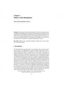
As temperature is decreased below T = 1.0J1 , the relaxation becomes very slow. We present, in Figs. 1(a) and 1(b), typical results of the MC sweep dependence of M2 at T = 0.9J1 in the conventional MC and CHB methods, respectively. Figure 1(a) shows most clearly the 6
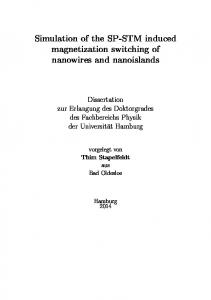
difficulty of the computer simulation of the ANNNI model as mentioned above. However, we could get its equilibrium value within a reasonable number of MC sweeps using the CHB method as seen in Fig. 1(b). We calculated the average values hM2 i at different temperatures using both the methods. Results are presented in Figs. 2(a) and 2(b) for the conventional MC method and the CHB method, respectively. At all temperatures, in the CHB method, we could get the same values starting with the two initial spin configurations in contrast with the conventional MC method [22]. Thus, we conclude that the CHB method, in fact, relieve the difficulty of the computer simulation of the ANNNI model. We have proposed a new update algorithm of the spin configuration and demonstrated its efficiency in the ANNNI model in two-dimensions. We should note again that the algorithm is a natural generalization of the conventional heat bath algorithm and applicable to various systems with short-range interactions. Since a large fluctuation of the spin configuration may occur for every MC sweep, the CHB method is particularly useful for studying equilibrium properties of complex systems such as spin-glasses [23]. We also note that we may perform much more effective MC simulation by combining the CHB method with extended ensemble methods such as the exchange MC method [8]. The authors wish to thank Dr. T. Nakamura for valuable discussions. They also wish to give their thanks to Dr. S. Fujiki for showing them his unpublished data of the ANNNI model. This work was partly financed by a Grant-in-Aid for Scientific Research from the Ministry of Education, Science and Culture. The simulations were made partly on FACOM VPP500 at the Institute for Solid State Physics in University of Tokyo.
7
REFERENCES [1] K. Binder, The Monte Carlo Method in Condensed Matter Physics, Second, Corrected and Updated Edition (Springier-Verlag Berlin Heidelberg 1995). [2] R. H. Swendsen and J. S. Wang, Phys. Rev. Lett. 58, 86 (1987). [3] U. Wolff, Phys. Rev. Lett. 62, 361 (1989). [4] P. W. Kasteleyn and C. Fortuin, J. Phys. Soc. Jpn. Suppl. 26s, 11 (1969). [5] R. H. Swendsen and J. S. Wang, Phys. Rev. Lett. 57, 2607 (1986). [6] B. A. Berg and T. Neuhaus, Phys. Lett. B 267, 249 (1991). [7] E. Marinari and G. Parisi, Europhys. Lett. 19, 451 (1992). [8] K. Hukushima and K. Nemoto, J. Phys. Soc. Jpn. 65, 1604 (1996). [9] O. Koseki and F. Matsubara, to appear in J. Phys. Soc. Jpn. [10] O. Koseki and F. Matsubara, in preparation. [11] W. B. Yelon, D. E. Cox and M. Eibsch¨ utz, Phys. Rev. B12, 5007 (1975). [12] M. Mekata and K. Adachi, J. Phys. Soc. Jpn. 44, 806 (1978). [13] See, e.g., W. Selke, in PHASE TRANSITIONS, ed. C. Domb and J. L. Lebowitz (Academic Press, 1992), Vol. 15, p. 1, and references therein. [14] I. Morgenstern and K. Binder, Phys. Rev. Lett. 43, 1615 (1979). [15] The CHB method is different from the cluster-flip methods [2,3]. The term cluster in the CHB method denotes an ensemble of spins in a fixed part of the lattice in contrast with that in the cluster-flip methods in which the term is used as an ensemble of connected spins with the same sign. In the cluster-flip methods, clusters themselves are generated in accordance with the Boltzmann weight and the clusters may extend over the lattice. In the CHB method, clusters with a predetermined shape are treated and then the 8
numbers of connected spins which may flip simultaneously are limited. However, if in each of the clusters there exist many spin configurations which have almost the same energy, one of them is selected in accordance with its Boltzmann weight. [16] W. Selke, K. Binder, and W. Kinzel, Surf. Sci. 125, 74 (1983) [17] Since the two walls are never linked, the minimum change of the chain arrangement is that from · · · 2 | 2 2 2 2 2 2 2 2 | 2 · · · to · · · 2 | 1 2 3 2 2 3 21 | 2 · · ·. [18] W. Selke and M. E. Fisher, Phys. Rev. B 20 257 (1979). [19] By using the CHB method with M = 8, we can readily add the walls at the ends and put them inside the lattice and vice versa. [20] W. Selke, Z. Physik B 43, 335 (1981). [21] J. Villain and P. Bak, J. Physique 42, 657 (1981). [22] In a standard UNIX machine, we need about 30 times much CPU time per one MC sweep in the CHB method with M = 8 than that in the conventional single-spin-flip method. However, we only need about one-hundredths of MC sweeps even for T > 1.0J1 , to get similar accuracy of data, and the ratio becomes much smaller at lower temperatures. [23] T. Shirakura and F. Matsubara, in preparation.
9
FIGURES FIG. 1. The MC sweep dependences of the order parameter M2 at T = 0.9J1 starting with two initial spin configurations of a paramagnetic phase (PARA) and the (2, 2) antiphase (AP) by (a) the conventional MC method and (b) the CHB method. FIG. 2. The temperature dependences of the average value of the order parameter hM2 i starting with two initial spin configurations of a paramagnetic phase (PARA) and the (2, 2) antiphase (AP) by (a) the conventional MC method and (b) the CHB method. In the conventional MC method, the averages were taken over 2 × 10⁴ − 4 × 10⁴ and 1 × 10⁵ − 1.5 × 10⁵ MC sweeps for T ≥ 1.0J1 and T ≤ 0.9J1 , respectively. On the other hand, in the CHB method, those were taken over much smaller numbers of MC sweeps, i.e., 5 × 10² − 10 × 102 and 1 × 10⁴ − 1.5 × 10⁴ MC sweeps for T ≥ 1.0J1 and T ≤ 0.9J1 , respectively.
10
(a) 1.1 1.0
M2
0.9
AP PARA
0.8 0.7 0.6 0.5 0.4 1
101
102 103 MC sweeps
104
105
(b) 1.1 1.0
M2
0.9 0.8 0.7 0.6 AP
0.5
PARA
0.4 1
101
102 103 MC sweeps
FIG.1.
104
105
F. Matsubara et al.
(a) 1.0 AP PARA
< M2 >
0.8 0.6 0.4 0.2 0.0 0.6
0.8
1.0
1.2
1.4
1.6
1.8
2.0
T/J1
(b) 1.0 AP PARA
< M2 >
0.8 0.6 0.4 0.2 0.0 0.6
0.8
1.0
1.2
1.4
1.6
1.8
2.0
T/J1
FIG.2.
F. Matsubara et al.