traffic, CMAC allows sensor nodes to operate at very low duty cycles. ... CMAC
first uses anycast to wake up forwarding nodes, and then converges gradually ...
CMAC: An Energy Efficient MAC Layer Protocol Using Convergent Packet Forwarding for Wireless Sensor Networks SHA LIU, KAI-WEI FAN and PRASUN SINHA Department of Computer Science and Engineering, The Ohio State University Email: {liusha,fank,prasun}@cse.ohio-state.edu Low duty cycle operation is critical to conserve energy in wireless sensor networks. Traditional wake-up scheduling approaches either require periodic synchronization messages or incur high packet delivery latency due to the lack of any synchronization. To simultaneously achieve the seemingly contradictory goals of energy efficiency and low latency, the design of a new low dutycycle MAC layer protocol called Convergent MAC (CMAC) is presented. CMAC avoids synchronization overhead while supporting low latency. By using zero communication when there is no traffic, CMAC allows sensor nodes to operate at very low duty cycles. When carrying traffic, CMAC first uses anycast to wake up forwarding nodes, and then converges gradually from routesuboptimal anycast with unsynchronized duty cycling to route-optimal unicast with synchronized scheduling. To validate our design and provide a usable module for the research community, CMAC has been implemented in TinyOS and evaluated on the Kansei testbed consisting of 105 XSM nodes. The results show that CMAC at 1% duty cycle significantly outperforms BMAC at 1% in terms of latency, throughput and energy efficiency. The performance of CMAC is also compared with other protocols using simulations, in which the results show for 1% and lower duty cycles, CMAC exhibits similar throughput and latency as CSMA/CA using much less energy, and outperforms SMAC, DMAC and GeRaF in almost all aspects. Categories and Subject Descriptors: C.2.1 [Network Architecture and Design]: Wireless communication; C.2.2 [Network Protocols]: Routing protocols General Terms: Algorithms, Design, Experimentation, Performance Additional Key Words and Phrases: Aggressive RTS, anycast, CMAC, convergent forwarding, MAC, wireless sensor networks
1. INTRODUCTION Duty cycling the radio is important to achieve long lifetime in wireless sensor network, but it usually causes performance degradation in throughput and latency which are critical metrics for various applications such as event tracking and surveilA preliminary version of this paper is published in [Liu et al. 2007]. This material is based upon work supported by the National Science Foundation under Grants CNS-0546630 (CAREER Award) and CNS-0403342. Any opinions, findings, and conclusions or recommendations expressed in this material are those of the author(s) and do not necessarily reflect the views of the National Science Foundation. Permission to make digital/hard copy of all or part of this material without fee for personal or classroom use provided that the copies are not made or distributed for profit or commercial advantage, the ACM copyright/server notice, the title of the publication, and its date appear, and notice is given that copying is by permission of the ACM, Inc. To copy otherwise, to republish, to post on servers, or to redistribute to lists requires prior specific permission and/or a fee. c 2008 ACM 0000-0000/2008/0000-0001 $5.00
ACM Journal Name, Vol. V, No. N, May 2008, Pages 1–32.
2
·
Sha Liu et al.
lance. These conflicting objectives motivate our design of a new MAC layer protocol called Convergent MAC (CMAC). Compared to other MAC layer protocols like BMAC [Polastre et al. 2004] and SMAC [Ye et al. 2004], CMAC can significantly reduce latency and improve throughput while supporting very low duty cycles. Current duty cycling MAC layer protocols for wireless sensor networks are either synchronized using explicit schedule exchanges or totally unsynchronized. However, both have their weaknesses and deficiencies. SMAC [Ye et al. 2004], TMAC [van Dam and Langendoen 2003] and DMAC [Lu et al. 2004] use periodic synchronization messages to schedule duty cycling and packet transmissions. Such message exchanges consume significant energy even when no traffic is present. BMAC [Polastre et al. 2004] uses unsynchronized duty cycling and uses long preambles to wake up receivers. However, the long preamble mechanism has the following three problems. First, the latency accumulated along multihop routes could be overwhelming due to the use of long preambles on each hop. Second, the energy consumed on preamble transmission and reception after the receiver has woken up is wasted. This is due to lack of information at the sender side about the wake-up schedule of the receiver, and thus the preamble length is chosen conservatively. Third, neighbor nodes other than the intended receiver will also be kept awake by the long preamble until the data packet transmission finishes, which is also wasteful since they are doing unneeded preamble overhearing. Polastre et. al. propose a link abstraction called Sensornet Protocol (SP) [Polastre et al. 2005] to adjust the preamble length by observing recent and nearby traffic. However, SP still relies on long preambles to initiate data flows, and it cannot dynamically select the next hop if the intended next hop is currently not available because of sleeping or interference. The above problems motivate our design of an energy efficient MAC layer protocol called Convergent MAC (CMAC). CMAC uses unsynchronized sleep scheduling like BMAC when there is no packet to transmit. While transmitting packets, CMAC first uses aggressive RTS (Section 3.2) to anycast (Section 3.3) packets to potential forwarders which wake up first and detect the traffic using double channel check (Section 3.2). Once the sender is able to transmit packets to a node with acceptable routing metric, CMAC converges from anycast forwarding to unicast (Section 3.4) to avoid the overhead of anycast. To validate the practicability of CMAC, we implement CMAC in TinyOS [TinyOS] and compare it with BMAC on the Kansei testbed [Arora et al. 2006]. We also evaluate CMAC in ns2 [NS2] against SMAC, a variant of GeRaF [Zorzi and Rao 2003b; 2003a; Casari et al. 2005], and 802.11 based CSMA/CA protocol. The results show CMAC outperforms other duty cycle scheduling protocols in all aspects while providing comparable throughput and latency performance as fully awake CSMA protocol. The main contributions of this paper are listed below: —We propose CMAC, a novel MAC layer protocol, which improves latency and energy efficiency by utilizing the proposed aggressive RTS, anycast and convergent packet forwarding mechanisms. —We analytically model the performance of both anycast and unicast based forwarding, and the performance of convergent packet forwarding; —We present details of the implementation and real field evaluation of CMAC to validate our design goals. ACM Journal Name, Vol. V, No. N, May 2008.
CMAC: An Energy Efficient MAC Layer Protocol Using Convergent Packet Forwarding
·
The rest of the paper is organized as follows. Section 2 summarizes other protocols in the literature and compares CMAC with them. Section 3 presents the design of CMAC. Section 4 presents our implementation and real field experimental results on Kansei testbed comparing CMAC with BMAC. Section 5 presents simulation results comparing CMAC with SMAC, DMAC, XMAC, CSMA/CA and a GeRaF variant. Finally, Section 6 concludes the paper. 2. RELATED WORK The lifetime of wireless sensor networks can be increased by periodically putting radios into sleep mode for some duration. However, nodes are unable to forward packets during sleeping. Therefore different approaches are proposed to ensure successful packet delivery in the presence of some sleeping nodes. These approaches can be broadly divided into two categories: synchronized and unsynchronized. Synchronized approaches: Protocols using this mechanism require nodes to periodically synchronize wake-up schedules with their neighbors using explicit messages, and nodes wake up and sleep according to the synchronized schedules. In SMAC [Ye et al. 2002], nodes exchange their wake-up schedules before following common schedules. In later work [Ye et al. 2004], the authors extend SMAC with adaptive listening to reduce latency. TMAC [van Dam and Langendoen 2003] uses the same mechanism as SMAC to synchronize nodes, but TMAC saves more energy by ending the listening period dynamically to reduce idle listening. DMAC [Lu et al. 2004] and the approach proposed in [Sichitiu 2004] schedule wake-up periods in a staggered fashion from sources to the sink such that packets can be forwarded without waiting for the next active period. In addition, the active period is divided into receiving and transmitting slots to avoid interference with the upstream and downstream nodes. DMAC can further dynamically adapt to higher traffic load by adjusting the wake-up frequency using more-to-send (MTS) packets. These synchronized approaches suffer unnecessary energy consumption on message exchanges when there is no traffic. Simple calculation for SMAC on Mica2 [Mica2] shows that synchronization messages consume almost 18% of the total energy in the absence of data traffic for 1% duty cycle, which implies 22% potential improvement to the lifetime by eliminating such message exchanges. Note that for duty cycle as low as 0.1%, this improvement could be 225%. Thus for operation at low duty cycles, synchronization messages should be eliminated. Unsynchronized approaches: Protocols in this category wake up the next hop by continuously sending preamble or packets, and thus eliminate the synchronization overhead. In BMAC [Polastre et al. 2004], nodes use clear channel assessment (CCA) and low power listening (LPL) to check the radio activity. If no activity is detected, the node goes back to sleep. Otherwise the node stays awake to receive the packet. In order to detect the traffic reliably, the packet preamble must be long enough. For example, if a node checks the channel every 300ms, the preamble transmission must last at least 300ms. However, the long preamble leads to high latency as explained in Section 1. Polastre et al. [2005] propose the Sensornet Protocol (SP) ACM Journal Name, Vol. V, No. N, May 2008.
3
4
·
Sha Liu et al.
protocol that works above the BMAC to reduce the overhead of long preambles by intelligently choosing the preamble length during the lifetime of data flows. However, SP cannot reduce the overhead for initiating a flow, in which the long preamble is still used. XMAC [Buettner et al. 2006] tries to mitigate the negative impact of long preambles by using strobed preambles, which shares a similar idea with the Aggressive RTS used in CMAC. However, XMAC has a significantly longer awake period (and thus higher duty cycle) than CMAC due to its mechanism of checking channel activities. Compared to an awake period of at most 6ms per duty cycle on XSM/Mica2 nodes, XMAC requires an awake period of 20ms on TelosB nodes. SCP-MAC [Ye et al. 2006] is a hybrid protocol utilizing both explicit synchronization and the preamble based technique. In SCP-MAC, nodes exchange synchronization messages at a frequency lower than SMAC, and preambles that are long enough to overcome the clock drift are transmitted before the data. Since SCPMAC also requires synchronization, energy is still consumed on message exchanges for this purpose. In addition, SP, XMAC and SCP-MAC cannot utilize the spatial diversity (Section 3.3) to dynamically select the next hop if the intended next hop is currently not available because of sleeping or interference. Another way to eliminate synchronization messages is to use MAC layer anycast to forward packets to the nodes that wake up earlier and are closer to the destination. In GeRaF [Zorzi and Rao 2003b; 2003a; Casari et al. 2005], the forwarding region (closer to the destination and within transmission range) is divided into a few sub-regions according to their distances to the destination. Upon forwarding a packet, the sender broadcasts an RTS packet to all nodes in the sub-region closest to the destination and expects a CTS reply. If there is no reply, the sender will broadcast another RTS packet to the sub-region that is the second closest to the destination. This process continues until a CTS is received or all sub-regions have been searched in which case the forwarding fails. If more than one node in the same sub-region happen to wake up and reply to the RTS packet at the same time, a collision will be detected by the sender since the sender will detect a busy channel while receiving invalid CTS packets. Then the sender will direct nodes in that sub-region to send CTS packets probabilistically until a valid CTS packet is received. After the RTS/CTS handshake, the sender can start to transmit the data packet to the one from which the valid CTS packet is received. Contention based forwarding protocols investigated in [F¨ ußler et al. 2003], [He ˇ et al. ], [Heissenb¨ uttel et al. 2004], [Skraba et al. 2004], [Chen et al. 2005a; 2005b], [Chen et al. 2005], [Witt and Turau 2005] share similar idea as GeRaF, but they resolve the contention among receivers by letting receivers monitor the channel to decide if they should send CTS packets. To favor receivers closer to the destination, they are assigned higher reply priorities (shorter waiting time before sending CTS packets). These contention based forwarding protocols have smaller forwarding overhead compared to GeRaF, but are proposed to circumvent the hot spot of the network and focus on eliminating the state (location of neighbors) maintenance, and thus they have not been employed to cooperate with low duty cycling. There are some other anycast protocols studied in this context, which either list potential receivers and their CTS transmission priorities in RTS packets ([Jain and Das 2005]), or probe neighbors in a round-robin manner to find an awake one ACM Journal Name, Vol. V, No. N, May 2008.
CMAC: An Energy Efficient MAC Layer Protocol Using Convergent Packet Forwarding
·
([Choudhury and Vaidya 2004]). RAW [Paruchuri et al. 2004] has similar idea as the basic anycast scheme described above, but it still requires explicit schedule exchange which should be avoided. All the anycast based approaches have the following three disadvantages. First, they either are not designed to work at low duty cycles, or rely on the receivers to detect the start of an RTS transmission, which implies longer active period than BMAC or more frequent wake-up. Second, the route could be longer since the optimal forwarding nodes may be asleep during anycasts. Third, the overhead of anycast RTS/CTS exchange is higher than unicast. Hence, although these anycast based protocols do not suffer from the overhead of synchronization messages, they incur higher overhead during data transmissions. 3. CONVERGENT MAC (CMAC) Motivated by the limitations of current approaches, we propose a MAC layer protocol called Convergent MAC (CMAC) that supports low latency and high throughput as well as low duty cycle operation. CMAC has three main components: Aggressive RTS equipped with double channel check for channel assessment, anycast to quickly discover forwarder, and convergent packet forwarding to reduce the anycast overhead. In this section, firstly an overview on how CMAC works is given, then the detailed design of CMAC follows. 3.1 CMAC Overview When there is no traffic in the network, CMAC uses unsynchronized wake-up scheduling with a pre-defined idle duty cycle (i.e., the duty cycle followed by nodes when there is no traffic). In this wake-up scheduling scheme, the duration between successive wake-ups is fixed according to the duty cycle and active period. However, to make the following mechanisms work at expected performance, we evenly randomize the wake-up time of each node for the first times it goes back to sleep after receiving a packet. While transmitting packets, the transmitter uses aggressive RTS (Section 3.2) instead of a long preamble to activate the receiver. To detect aggressive RTS, nodes periodically wake up and “double check” the channel for activities (Section 3.2). Unlike other unicast MAC layer protocols, CMAC initially uses anycasts (Section 3.3) to transmit packets to a potential forwarder that wakes up first. Awake candidate receivers will contend to be the anycast receiver by prioritizing their CTS transmissions according to their routing metrics to the sink. After receiving a CTS, the data packet will be sent to the sender of the CTS immediately. Nodes will keep their radios “on” for a short duration anticipating more packets whenever they successfully receive data packets destined to them. This reduces the overhead of searching for awake forwarders in subsequent transmissions. To overcome the disadvantage of anycast such as higher RTS/CTS overhead and route stretch, CMAC converges from anycast to unicast once it establishes contact with a receiver having good enough routing metric. 3.2 Aggressive RTS The long preamble mechanism of BMAC incurs high latency in order to ensure that the receiver is awake before sending the data. However, the receiver may wake up ACM Journal Name, Vol. V, No. N, May 2008.
5
6
·
Sha Liu et al.
much earlier than the end of the preamble, which makes part of the preamble transmission wasteful. We propose to use aggressive RTS to replace the long preamble, which breaks up the long preamble into multiple RTS packets (also called an RTS burst). The RTS packets do not use long preambles, and are separated by fixed short gaps each of which allows receivers to send back CTS packets. Once the transmitter receives a CTS, it sends the data packet immediately. Each gap need not accommodate an entire CTS transmission as long as the RTS sender can detect the preamble and cancel the next RTS transmission accordingly. The number of RTS packets to be sent in one RTS burst depends on the duty cycle length. For the same duty cycle length, the duration of one RTS burst is roughly the same as the long preamble used by BMAC. If nodes uniformly randomly wake up during each duty cycle, the expected latency at each hop could be reduced by half. Using pseudo code, the operations of RTS senders are summarized as Algorithm 1 and 2. Algorithm 1: OnBackoffEnds(pkt) 1 2 3 4 5 6 7 8 9 10 11 12 13
// Try to initiate an RTS burst for packet pkt. rts cnt ← 1; RSSI ← GetRSSI(); if (RSSI < CST hreshold) then rts.src ← GetMyLocation(); rts.dst ← pkt.dst; rts.dist ← Distance(rts.src, rts.dst); rts.nav ← GetNav(); Send(rts); rts cnt ← 1; InterRTSTimer.start(Tinter−RT S ); else BackoffTimer.start(RandomUnifrom(0,maxBackof f )); end
To allow nodes to work at a very low duty cycle, nodes must assess the channel very quickly each time they wake up. However, if the receiver wakes up during the gap between two RTS transmissions, it may miss the RTS burst. So we propose to use double channel check which works by assessing the channel twice with a fix short separation between them each time a node wakes up. For each channel check, nodes sample the channel for up to 5 times. Between these two channel checks, the radio could be put to sleep mode to save energy. If the first check detects a busy channel, the second check will be canceled (Fig. 1(a)). Otherwise, the second check is performed (Fig. 1(b)). The positive conclusion on busy channel from either check will keep the node awake anticipating an RTS. To prevent the scenario in Fig. 1(c), the interval must be shorter than the RTS transmission time. This can be satisfied by padding RTS packets with extra bytes if needed. (We discuss the choice of these parameters in Section 4 where the implementation details are presented.) To avoid the scenario where a node wakes up and detects the energy of the last RTS packet in a burst, the entire duration of an aggressive RTS burst is set to be one more RTS ACM Journal Name, Vol. V, No. N, May 2008.
CMAC: An Energy Efficient MAC Layer Protocol Using Convergent Packet Forwarding
·
Algorithm 2: OnInterRTSEnds() 1 2 3 4
5 6 7 8 9 10 11
// Decide if more RTS packets should be sent Td ← GetDutyCycleLength(); Td maxRT S ← ; TxTime(rts)+TinterR T S while (rts cnt ≤ maxRT S) do if (RadioState 6= IDLE) then //Already detected a valid preamble // Cancel all following RTS transmissions return; else Send(rts); rts cnt + +; InterRTSTimer.start(Tinter−RT S ); end end
packet longer than receiver’s duty cycle length. Let d, r, g, n denotes the duty cycle length, the time to transmit an RTS packet, the interval between two RTS packets, and the number of RTS packets in a burst, respectively. Then n must satisfy n>
d + 1. r+g
(1)
Such a “double-check” mechanism ensures that nodes will not miss any RTS burst in their vicinity. The operations of double channel check are summarized in the pseudo code shown in Algorithm 3 and 4. Algorithm 3: OnWakeUp() 1 2
3 4 5 6 7 8 9 10 11 12
13
// Perform the first channel check after waking up. Td ← GetDutyCycleLength(); Ti ← GetDoubleCheckInterval(); // Same as BMAC, use up to 5 samples to improve the robustness maxSamples ← 5; i ← 1; repeat RSSI ← GetRSSI(); if (RSSI < CST hreshold) then ChannelCheckTimer.start(Ti); return; end i + +; until (i = maxSamples) ; // No second channel check since the first one is positive Recv(pkt);
ACM Journal Name, Vol. V, No. N, May 2008.
7
8
·
Sha Liu et al.
Algorithm 4: OnChannelCheckTimerExpire() 1 2 3 4 5 6 7 8 9 10 11
12
// Perform the second channel check. Td ← GetDutyCycleLenght(); maxSamples ← 5; i ← 1; repeat RSSI ← GetRSSI(); if (RSSI < CST hreshold) then Sleep(Td ); return; end i + +; until (i = maxSamples) ; // The second channel check is positive, start to receive the packet Recv(pkt); RTS
RTS
RTS
RTS
RTS
Channel check (b) Case 2
Channel check (a) Case 1
RTS
Channel check (c) Case 3
Fig. 1. Double Channel Check used by CMAC. (a) The first check detects the RTS burst. (b) The second check detects the RTS burst. (c) impossible if RTS length is chosen carefully.
RTS
RTS
RTS
RTS
RTS
RTS time
CCA
No CCA
Fig. 2.
CCA in each aggressive RTS burst.
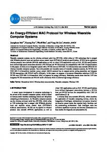
The cooperation of aggressive RTS and double channel check require both the gap between two RTS and the interval between two channel checks to be fixed. To achieve this, CMAC sends all RTS packets without clear channel assessment (CCA) except the first one (Fig. 2). Hence collisions can be avoided either by sensing a busy carrier before transmitting the first RTS packet, or by receiving the preamble of another RTS burst during an RTS gap. If more than one RTS burst completely overlap each other, then the entire RTS bursts will be resent after backoffs and sensing the carrier. 3.3 Anycast Based Forwarding Aggressive RTS can reduce per-hop latency by half on average for unicast. However, if nodes other than the unicast target can also reply to the transmitter, per-hop latency could be further reduced since some routing progress could be made while ACM Journal Name, Vol. V, No. N, May 2008.
CMAC: An Energy Efficient MAC Layer Protocol Using Convergent Packet Forwarding
mini-slot Sender Node in R1 Node in R1 Node in R2 Node in R3 Fig. 3.
RTS
·
CTS slot
Canceled RTS CTS Canceled CTS Canceled CTS Canceled CTS
CTS contention resolution. The first CTS cancels others.
the target nexthop is still asleep. We define the neighbor nodes of the transmitter that are closer to the destination as a forwarding set. Simple calculation shows for 1 duty cycle length 1 and forwarding set size n, it takes on average n+1 to get in contact with at least one of them. However, more than one node in the forwarding set may try to reply to the same RTS, and the one closest to the destination should be elected to receive the data packet. In CMAC, the CTS transmissions are prioritized according to the routing metrics of contending nodes. Nodes with better routing metrics can send CTS packets earlier, while other overhearing nodes cancel their CTS transmissions accordingly, and nodes that can make little progress are excluded. Our approach can work with routing metrics such as geographical distance, hop count, ETX[Couto et al. 2003], ETT[Padhye et al. 2004] and PRR×Dist[Seada et al. 2004]. In this paper, we only investigate the use of geographical distance to resolve CTS contentions. CMAC partitions the forwarding region into k subregions, R1 , R2 , . . . , R3 , such that nodes in Ri are closer to the destination than nodes in Rj for 1 ≤ i < j ≤ k (Fig. 4). Each gap between two consecutive RTS packets is divided into k subintervals called CTS slots. Nodes in region closer to the destination can send CTS packets in earlier CTS slots. In the rest of this paper, we use k = 3. Each CTS slot is further divided into several mini-slots to resolve the contention within each region, and each receiver will randomly choose one mini-slot to start its CTS transmission (Fig. 3). On detecting a busy channel, pending CTS transmissions will be canceled assuming the existence of another CTS. Note that even though the contention for sending CTS packets is low for very low duty cycles, the above scheme is still necessary as the number of awake nodes will increase with persistent traffic. The operations of the receiver are summarized in pseudo code in Algorithm 5 and 6. Other contention resolution schemes such as in [Rossi et al. 2007] and [Eisenman and Campbell 2006] are also proposed, but compared to our scheme, these schemes incur much higher overhead to maintain neighboring topology information. In low duty cycling sensor networks where the availabilities of nodes can vary dramatically within a short period, these schemes are not suitable. ACM Journal Name, Vol. V, No. N, May 2008.
9
10
·
Sha Liu et al.
Algorithm 5: OnRecvRTS(rts) 1 2 3 4 5 6 7 8 9 10 11 12 13 14 15 16 17 18
// Operations after receiving RTS packet rts. dst ← rts.dst; src ← rts.src; ds ← rts.dist; // Distance from RTS sender to the destination ; loc ← GetMyLocation(); d ← Distance(loc, dst); if (d > ds ) then // No participation if farther away than RTS sender nav = rts.nav; // Set network allocation vector (NAV) ; return; else// Participate the anycast if (Receiver is in region Rj ) then CT SSlots ← j − 1; M iniSlots ← RandomUniform(0,maxM iniSlots); cts.src = GetMyAddress(); cts.dst = src; cts.nav = rts.nav - TxTime(rts); CTSBackoffTimer.start(CT SSlots × (j − 1) + M iniSlots); end end
Algorithm 6: OnCTSBackoffEnds() 1 2 3 4 5 6
// Operations when the CTS backoff ends RSSI ← GetRSSI(); if (RSSI > CST hreshold) then return; else Send(cts); end
Fig. 4. Example of cost region generation in CMAC using geographical distance as routing metric. ACM Journal Name, Vol. V, No. N, May 2008.
CMAC: An Energy Efficient MAC Layer Protocol Using Convergent Packet Forwarding
·
3.3.1 Performance Analysis of Anycast . Anycast can establish contact with a forwarding candidate node faster than unicast, but this is achieved at the cost of higher overhead and less routing progress for each individual transmission. In this subsection, we analytically model the performance of anycast. The metric used in this analysis is the latency of each transmission normalized by its geographical routing progress called normalized latency. For the rest of the analysis, the length of a duty cycle is normalized to 1, and the notations used are summarized as follows. —L: normalized latency. —ρ: node density. —S: area of the forwarding region. —X: geographical progress made by anycast. —Y : the latency of finding the first awake node in the forwarding set. Its CDF is F (y) = 1 − (1 − y)n . Since the locations of nodes do no affect their wake-up scheduling, Y is independent of X. —r: transmission range. —r0 : the minimum progress required for a neighbor node to be present in the forwarding set. —d: distance from the transmitter to the destination. Note that lower duty cycle leads to longer sleep time in each cycle since the time to check the channel is fixed. Then for very low duty cycles, the RTS and data packet R1 1 . Then the transmission times could be ignored. Hence, E[Y ] ≈ 0 ydF (y) = ρS+1 expected normalized latency could be expressed as E[L] = E[
1 1 1 Y ] = E[Y ]E[ ] = E[ ], X X ρS + 1 X
(2)
where the second equality is due to the independence of X and Y . To compute E[ X1 ], consider the upper half of the forwarding region as region OAR in Fig. 5. As illustrated in Fig. 5, for any point B between O and R with _ x coordinate no less than r0 , its weight is x1 times the length of arc BC (Fig. 5), _ while the length of BC is _ |BC| = |CD| × 6 CDO |CD|2 + |OD|2 − |OC|2 = |CD| arccos 2|CD||OD| (d − x)2 + d2 − r2 . = (d − x) arccos 2d(d − x) Hence, S =
Z
r
_ |BC|dx
r0 r
=
Z
r0
(d − x) arccos
(3) (4) (5)
(6) (d − x)2 + d2 − r2 dx, 2d(d − x)
(7)
ACM Journal Name, Vol. V, No. N, May 2008.
11
12
·
Sha Liu et al. A
C
B O
Fig. 5.
R(r,0)
r0
D(d,0) x
1 ]. O is the sender, D is the destination. Calculation of E[ X
and 1 E[ ] = X =
Rr
1 _ r0 x |BC|dx
Rr
(8)
S 2
2
2
+d −r 1 (d − x) arccos (d−x) dx 2d(d−x) r0 x . Rr 2 2 2 +d −r (d − x) arccos (d−x) dx 2d(d−x) r0
(9)
There are three parameters affecting E[L]: r0 , S and ρ. S depends on r0 and d. Fig. 6(a) plots E[L] versus r0 for different d values when ρ = 10. It can be seen that for a certain node density, larger d leads to smaller E[L], but d only affects E[L] insignificantly. In Fig. 6(b) d is fixed to be 10, while ρ is varied from 5 to 15. It can be seen that higher node density clearly leads to smaller E[L]. In addition, for certain d and node density, there is an optimal value of r0 to optimize E[L] (the minimum points of the curves in Fig. 6(a) and 6(b)). Fig. 6(c) plots the optimal r0 for various d and ρ values. It can be observed that the optimal r0 can stabilize within range (0.24r, 0.33r) across a wide range of d and ρ values. With the increase in density, the optimal r0 decreases. But for higher density, there is a wider range for r0 in which the normalized latency performance is close to the optimal. Hence, for the sake of simplicity, we use r0 = 0.3 in our evaluations. After finding the optimal r0 (r0 is following discussions), nodes still need to decide to use anycast or unicast. For unicast, the normalized latency is bounded 1 by 2r . Hence for anycast to be superior than unicast on average, it should have lower expected normalized latency. Using Equation (2), this criterion leads to the following critical node density above which anycast is better ρ>
2rE[ X1 ] − 1 . S
(10)
Fig. 6(d) shows the critical density for nodes located at different distance to the sink. It can be seen that the critical density drops sharply when the distance to the sink is greater than r. In all scenarios evaluated in Section 4 and 5, every node either has its critical density requirement satisfied, or has the sink within its transmission range and thus it uses unicast. ACM Journal Name, Vol. V, No. N, May 2008.
0.54 0.52 0.5 0.48 0.46 0.44 0.42 0.4 0.38 0.36 0.34 0.32
1.2
d=5r, rho=10 d=10r, rho=10 d=15r, rho=10
E[L] (normalized to 1 duty cycle)
E[L] (normalized to 1 duty cycle)
CMAC: An Energy Efficient MAC Layer Protocol Using Convergent Packet Forwarding
13
d=10r, rho=5 d=10r, rho=10 d=10r, rho=15
1.1 1 0.9 0.8 0.7 0.6 0.5 0.4 0.3 0.2
0.1
0.2
0.3 0.4 0.5 r0 (normalized to r)
0.6
0.7
0
d=5r d=100r
0.34 0.32 0.3 0.28 0.26 0.24 0.22 0.2 0
10
20 30 40 50 60 70 80 Density (Nodes per Unit Square)
0.1
0.2
0.3
0.4 0.5 0.6 0.7 r0 (normalized to r)
0.8
0.9
1
18
20
(b) Anycast Performance, vary ρ
90
(c) Optimal r0
100
Critical Node Density (Nodes per Unit Square)
(a) Anycast Performance, vary d
Optimal r0 (normalized to r)
·
9.5 9 8.5 8 7.5 7 6.5 6 5.5 2
4
6
8 10 12 14 d (Normalized to r)
16
(d) Critical Density for Anycast
Fig. 6. Numerical results for anycast performance analysis. Using this formula, we can compute if nodes should use anycast or unicast given the parameters of the network or a region of the network. Note that if a node knows the number of nodes in its forwarding set, it can locally make the decision using a similar approach. Specifically, for a node with n neighboring nodes in its forwarding set with each node making ri progress (1 ≤ i ≤ n), it can decide if anycast is better if X 1 1 1 < . n(n + 1) i=1 ri 2 max1≤i≤n {r} n
(11)
3.3.2 Choose the Optimal Forwarding Set . Using anycast, nodes that are closer to the destination and wake up earlier can pick up the packet and make some progresses in routing. However, as shown in Section 3.3.1, including every node in the forwarding region may not be optimal, and hence the performance could be improved if the nodes included in the forwarding set are chosen carefully. In ACM Journal Name, Vol. V, No. N, May 2008.
14
·
Sha Liu et al.
this section, we present two algorithms to select the optimal forwarding set. The first one chooses the forwarding set to optimize the normalized latency defined in Section 3.3.1, and the second one attempts to optimize the end-to-end latency. Optimizing Expected Normalized Latency Given m nodes {Ni1 , Ni2 , . . . , Nim } in the forwarding set with node Nik , k = 1, . . . , m, making geographical progress of ri , the normalized latency is X 1 1 E[L({ri1 , ri2 , . . . , rim })] = . m(m + 1) j=1 rij m
(12)
Hence if a sender has n candidate nodes in its forwarding region, there are totally 2n − 1 possible forwarding sets for this node. However, computing the expected normalized latency for all these sets are computational inefficient. To reduce such computation overhead, we propose Algorithm 7 to find the optimal forwarding set. This algorithm adds one node to the forwarding set each time and computes the expected normalized latency provided by the current set. The nodes are added into the set in a way such that nodes closer to the sink are added earlier. In other words, Algorithm 7 computes the normalized latencies of all prefix sets, instead of all subsets, of the sorted candidate set, and selects the prefix set that has the lowest expected normalized latency. Algorithm 7: Choosing forwarding set to optimize local expected normalized latency Input: Nodes {(N1 , r1 ), (N2 , r2 ), . . . , (Nn , rn )} with rj > rk for j < k Result: Optimal forwarding set in terms of expected normalized latency 1 OptimalSet ← {}; 2 max ← ∞; 3 i ← 1; 4 while (i ≤ n) do 5 if (E[L({r1 , r2 , . . . , ri })] < max) then 6 max ← E[L({r1 , r2 , . . . , ri })]; 7 OptimalSet ← L({r1 , r2 , . . . , ri }); 8 end 9 end 10 return OptimalSet;
Even though Algorithm 7 does not search all possible subsets, it can find optimal forwarding set. This can be seen simply by a substitution argument. Suppose the optimal set S1 is not a prefix set, then there exists a node Nj in the forwarding region that is closer to the destination than at least one node, say node Nk , in S1 . Then if we substitute Nk in S1 by Nj to form a new set S2 , then the expected normalized latency of set S2 will be lower than that of set S1 . Hence, it follows that checking all prefix sets is sufficient for finding the optimal forwarding set as done by Algorithm 7. ACM Journal Name, Vol. V, No. N, May 2008.
CMAC: An Energy Efficient MAC Layer Protocol Using Convergent Packet Forwarding
·
Optimizing Expected End-to-End Latency The ultimate goal of finding optimal forwarding set is to minimize the end-to-end latency from the sender to the receiver. Hence, if the sender has the knowledge on the expected latencies from all nodes in its forwarding region to the destination, then it can use such information to select the optimal forwarding set. Given m nodes {Ni1 , Ni2 , . . . , Nim } included in the forwarding set, and the average end-toend latency from node Nik , k = 1, . . . , m, to be li , then the expected end-to-end latency from the sender is 1 X 1 1 . + m + 1 m j=1 lij m
E[L({li1 , li2 , . . . , lim })] =
(13)
If the nodes included in the forwarding set are sorted in ascending order of their average end-to-end latency to the destination, it can be shown that checking all prefix sets is sufficient for finding the optimal forwarding set. The proof is also by the substitution argument similar as the one for Algorithm 7. Hence, we propose Algorithm 8 to choose the optimal forwarding set if the average end-to-end latencies from all nodes in the forwarding region are known. Algorithm 8: Choosing forwarding set to optimize expected end-to-end latency Input: Nodes {(N1 , l1 ), (N2 , l2 ), . . . , (Nn , ln )} with lj < lk for j < k Result: Optimal forwarding set in terms of expected end-to-end latency 1 OptimalSet ← {}; 2 max ← ∞; 3 i ← 1; 4 while (i ≤ n) do 5 if (E[L({l1 , l2 , . . . , li })] < max) then 6 max ← E[L({l1 , l2 , . . . , li })]; 7 OptimalSet ← L({l1 , l2 , . . . , li }); 8 end 9 end 10 return OptimalSet;
3.4 Converging from Anycast to Unicast Although anycast obviates the need for synchronization messages and has better chance to make progress in packet forwardings than unicast, it has two main shortcomings. First, anycast may choose suboptimal routes because the best next hop is sleeping or due to interference. Second, the overhead of anycast RTS/CTS exchange is usually higher than its unicast counterpart. Hence, a mechanism is needed to reduce the overhead incurred by anycast, and we propose convergent packet forwarding to resolve these problems as follows. In CMAC, the node will remain awake for a short duration after receiving a data packet (The choice of this duration is analyzed in Section 3.4.2). During this period, a node with better routing metric could wake up and become the receiver of the ACM Journal Name, Vol. V, No. N, May 2008.
15
16
·
Sha Liu et al.
next anycast. If the latest anycast receiver has a routing metric close to the best (both falling in the same CTS slot), CMAC will use unicast instead to reduce the overhead. Taking Fig. 4 as an example, node C might be the earliest to wake up, followed by B and then by node A. Since A is already in the optimal region (region R1 in Fig. 4), the transmitter starts to unicast to A regardless if there is any other sleeping node in R1 with greater progress. However, it is possible that there is no node in region R1 in Fig. 4. Hence if the transmitter cannot find a better next hop than the current one after a duty cycle length, it switches to unicasting. In this way, the packet forwarding converges from anycast to unicast for each link. After some time without successful data packet reception, CMAC will timeout and nodes will again start following unsynchronized idle duty cycles. The unicast after such convergence may or may not use normal RTS/CTS. In our experiments, CMAC does not use RTS/CTS after convergence for fair comparison with BMAC. In our simulations, CMAC uses normal RTS/CTS that is similar as 802.11 after convergence for comparison with 802.11, SMAC and GeRaF. If the event moves fast, the source nodes may continuously change with each of them generating only a small number of packets. In this case, the convergence may still happen at places closer to the destination where the routes may be more stable. For some other cases such as low data rates, the convergence may not happen, but CMAC can still use aggressive RTS and anycast to make quick progress towards the sink. 3.4.1 Convergence Latency . If the sender is backlogged, the convergence from anycast to unicast either when the sender can not find a better node than current one, or when a node in the best forwarding subregion (R1 in Fig. 4) wakes up and its CTS packet is received by the sender. For the former case, the convergence takes one duty cycle to finish since this duration is needed to learn that there are no better forwarders. For the latter case, using the notations in Section 3.3.1, the expected latency Lc for at least one node is this region to wake up is Lc =
1 , ρS1 + 1
(14)
where S1 is the area of the best forwarding subregion and is derived similarly as Eqn. (7). Let r1 denote the minimum geographic progress made by nodes in this region, then Z r (d − x)2 + d2 − r2 dx. (15) (d − x) arccos S1 = 2d(d − x) r1 Using the forwarding region division scheme in Fig. 4, the latency from sending the first RTS packet until the convergence finishes is plotted in Fig. 3.4.1. From the figure, it can be observed that the convergence latency decreases slowly and insignificantly with the increase in d due to the slow change of the forwarding region shapes. Density ρ has more significant impact on the convergence time with higher density leading to faster convergence. 3.4.2 Choice of Awake Period Length after Receiving a Packet. To reduce the packet delivery latency, a long awake duration after receiving each packet is preferred. But longer awake period also leads to more energy consumption. Hence, ACM Journal Name, Vol. V, No. N, May 2008.
Convergence Latency (Normalized to 1 Duty Cycle)
CMAC: An Energy Efficient MAC Layer Protocol Using Convergent Packet Forwarding
1
·
rho=10 rho=15 rho=50 rho=100
0.8 0.6 0.4 0.2 0
10 20 30 40 50 60 70 80 90 100 Distance to the Sink (Normalized to Transmission Range)
Fig. 7. Numerical results for convergence latency. nodes need to optimize the length of this period based on the observed traffic information such as average packet arrival rate to accommodate latency or energy consumption requirements. In what follows, we use a simple model to analyze the latency and power consumption under different awake durations. The duty cycle length is again normalized to 1, and other denotations are listed below. —A: active duration after receiving a packet. —Z: packet arrival interval (a random variable). —G: the CDF of Z. —λ: average packet arrival rate. —pr : power for idle listening and receiving. —pt : power for transmitting. If the next packet arrives at the sender before the active duration A times out, which happens with probability P {Z < A} = G(A), unicast will be used. Hence the latency is 0 (before transmitting the data packet), and the idle listening for period Z contributes to the entire energy consumption. Otherwise, if the next packet does not arrive at the sender after the active duration times out, which happens with probability P {Z ≥ A} = 1 − G(A), anycast will be used. Hence the average latency is the average time needed to contact at least one receiver which 1 , and the average energy consumption has two components, idle listening is n+1 1 . Therefore, the average for duration A and transmitting aggressive RTS for n+1 latency La and average energy consumption Ea are 1 (1 − G(A)), n+1 Ea = G(A)pr E[z|z < A] La =
ACM Journal Name, Vol. V, No. N, May 2008.
17
·
18
Sha Liu et al.
0.1
0.16
(lambda=10,n=9) (lambda=10,n=14) (lambda=10,n=19) (lambda=20,n=19) (lambda=20,n=29) (lambda=20,n=39)
0.09 0.08 0.07
0.12
0.06
0.1 Ea
La
(lambda=10,n=9) (lambda=10,n=14) (lambda=10,n=19) (lambda=20,n=19) (lambda=20,n=29) (lambda=20,n=39)
0.14
0.05 0.04
0.08
0.03
0.06
0.02 0.04
0.01 0
0.02 0
0.1
0.2
0.3
0.4
0.5
0
0.2
A
0.4
0.6
0.8
1
A
(a) Impact of A on Latency
(b) Impact of A on Energy
Fig. 8. Numerical results for convergence performance analysis. +(1 − G(A))(pr A + pt
1 ). n+1
If the packet arrival process is Poisson with parameter λ, then G(A) = 1 − e−λA , and RA 1 zλe−λz dz − (A + λ1 )e−λA . (16) E[z|z < A] = R0 A = λ −λz dz 1 − e−λA 0 λe
Hence,
e−λA , n+1 pt pr pr +( − )e−λA . Ea = λ n+1 λ La =
(17) (18)
We plot in Fig. 8(a) and Fig. 8(b), La and Ea versus A for different λ and n (pr = 1 and pt = 1.5). It can be seen that La decreases with the increase of A given a certain n, but Ea has more complex variation patterns. Using Equation (18) we can see that there are three cases as follows. pt < pλr , or equivalently if the expected energy consumption in transmitting (1) If n+1 RTS packets is smaller than the expected energy consumed in idle listening, Ea increases with A up to pλr . pt (2) If n+1 = pλr , Ea = pλr . pt (3) If n+1 > pλr , Ea decreases with A down to pλr .
3.5 Synchronized Wake-up Schedule In order to save more energy after convergence, nodes can synchronize with their upstream and downstream nodes to use synchronized wake-up schedule instead of keeping fully awake. In this section, we present a CMAC variant called CMAC-S using a staggered scheduling idea similar to DMAC [Lu et al. 2004] after convergence. When the transmitter intends to converge from anycast to unicast, it synchronizes its schedule with the receiver. The two nodes will maintain the staggered schedule ACM Journal Name, Vol. V, No. N, May 2008.
CMAC: An Energy Efficient MAC Layer Protocol Using Convergent Packet Forwarding
·
as long as there is traffic between them. After a certain duration without traffic, the nodes go back to using unsynchronized duty cycling. In CMAC-S, the transmission and reception slots are split. The synchronized schedule is illustrated in Figure 9. Each wakeup cycle has a sleep time slot and an active time slot. In active time slot, time is divided into a receiving slot and a transmitting slot. Nodes can only transmit data during the transmitting slot. Therefore, the downstream nodes must schedule their receiving time slot to match their upstream node’s transmitting slot. Figure 10 illustrates the synchronization schedules of a few synchronized nodes. The receiving and transmitting slots are staggered such that the upstream nodes can transmit to downstream nodes without contention between them. The staggered schedule allows nodes to forward packets from the source to the sink with low delay.
Fig. 9.
Fig. 10.
Synchronization Schedule.
Staggered synchronization schedules.
When two nodes agree to synchronize, they must schedule their wakeup periods in a staggered way. We consider the following two cases for synchronization. —The sender is the source and is not synchronized. When a sender is not synchronized, the schedule can be started at any time. Figure 11 illustrates a scenario where an unsynchronized sender wants to synchronize with the receiver. The schedule will be started as of the time the sender sends the RTS packet for the first successful data transmission. —The sender is an intermediate node, and is already synchronized with its upstream node. As the sender is already synchronized, it can not change its schedule. So when it needs to synchronize, it explicitly indicates the time elapsed since the beginning of the current transmitting slot (see Figure 12). The receiver uses this ACM Journal Name, Vol. V, No. N, May 2008.
19
20
·
Sha Liu et al.
offset to determine its staggered wakeup schedule to properly match the sender. Therefore even if the transmission failed for the first few tries, the receiver can still know the time to start the schedule.
Fig. 11. An unsynchronized sender synchronizes with an unsynchronized receiver. The
schedule will be started as of the time the sender sends the RTS packet of the first successful data transmission.
Fig. 12. A synchronized sender synchronizes with an unsynchronized receiver. The sender explicitly indicates the receiver the time offset of its schedule in DATA header.
Multiple sources may simultaneously send data in case of a static event that triggers multiple nodes or in case of a mobile event. When multiple sources need to report data to the sink synchronization needs to be managed across merging routes. If a sender is not synchronized but the receiver is already synchronized with another sender (at the junction of two merging flows), it follows the receiver’s schedule. The receiver indicates the time elapsed since the beginning of the last receiving time slot in the CTS header, and the sender learns when to start its transmitting slot. If both the sender and the receiver are synchronized with their upstream nodes (receiver is synchronized with another sender) but they are not synchronized with each other, the following approaches can be used to adjust their synchronization: —The sender can match the receiver’s schedule and request its upstream nodes to adjust their wakeup schedules. However, this causes a ripple effect that needs to be propagated to the leaf nodes of the tree. ACM Journal Name, Vol. V, No. N, May 2008.
CMAC: An Energy Efficient MAC Layer Protocol Using Convergent Packet Forwarding
·
—The receiver switches to a wakeup schedule that satisfies the new sender as well as the old sender(s). However, this requires the receiver to maintain a higher active duty cycle (see Figure 13). —The sender splits its receiving and transmitting slots to match with its upstream as well as downstream nodes as shown in Figure 14. In CMAC, since unicast routes are not pre-constructed, it is difficult and may involve significant overhead to ensure a strict staggered schedule along the routing tree like in DMAC. Hence we adopt this scheme in our simulation due to the lower overhead. We do not use the More-To-Send control packets like in DMAC [Lu et al. 2004] since the schedule will always be followed until it times out.
Fig. 13. A synchronized receiver accommodates a synchronized sender by extending its
receiving slot.
Fig. 14. A synchronized sender accommodates a synchronized receiver by splitting its re-
ceiving and transmitting slots to match the receiver’s slots.
4. EXPERIMENTAL EVALUATION Our TinyOS [TinyOS ] implementation1 of CMAC is based on XSM [Dutta et al. 2005] which is similar to Mica2 mote [Mica2] using the same CC1000 radio [CC1000] and processing board. We set the mini-slot length to the transmission time of 1 byte on CC1000 radio which is 416µs, a period long enough to accommodate the propagation delay and busy channel detection (One channel sampling takes about 265µ to finish). Other parameters are summarized in Table I. The Kansei testbed consists of 105 XSM nodes forming a 15 × 7 topology with node separation of 3 feet. The transmission range is set to 4 rows/columns in the testbed. Each XSM node 1 Code
available at http://www.cse.ohio-state.edu/~liusha/cmac. ACM Journal Name, Vol. V, No. N, May 2008.
21
22
·
Sha Liu et al.
Table I. Implementation Parameters Parameter Value RTS interval 7.488ms Double channel check interval 10ms CTS-slot length 1.25ms Number of CTS-slots 3 Mini-slot length 416µs Number of mini-slots 6 RTS packet size 44 bytes
is attached to a Linux-based stargate [Stargate] through which command messages are sent to trigger the generation of packets. We evaluate the throughput, latency and energy efficiency of CMAC against BMAC for two basic event scenarios, static event and moving event. Here throughput refers to the total number of packets received at the sink in 600 seconds, latency is the average end-to-end delay experienced by a packet, and energy efficiency refers to the energy consumption of the entire network for delivering one 36-byte packet to the sink (called normalized energy). We measure the energy consumption by keeping track of the duration nodes spend on idle, receiving, transmitting and sleeping states, and the power consumption rate presented in [Polastre et al. 2004] is used to calculate the total energy consumption. Since CMAC uses geographical progress as the metric to classify potential forwarding nodes, we run greedy geographic routing on top of BMAC and guarantee that there is no routing void. The SP protocol [Polastre et al. 2005] can establish a light weight path without using long preambles for all transmissions, but it still suffers when initiating a flow or when the traffic is sparse. The comparison with SP is left as our future work. Note that the double channel check almost doubles the times of channel sampling in BMAC. Thus CMAC consumes more energy on channel assessment than BMAC if the duty cycle length is the same. To be fair, we evaluate CMAC with duty cycle length double that of BMAC in this section. For example, if BMAC uses 300ms duty cycle length, CMAC will use 600ms. Since using 300ms duty cycle length in BMAC is roughly 1% duty cycle, we denote it by BMAC 1%, and denote CMAC using 600ms duty cycle length as CMAC 1%. To provide the baseline for throughput and latency evaluation, we also gathered the data for BMAC and CMAC without duty cycling, denoted by BMAC 100% and CMAC 100% respectively. 4.1 Static Event Scenarios In this set of experiments, we emulate an event happening at one corner of the testbed. The source node sends all packets to the sink located at the diagonally opposite corner. We vary the data rate at source nodes, and the results are shown in Fig. 15. For low data rates (0.2 ∼ 0.5 packets/sec.), both CMAC 1% and BMAC 1% can deliver all packets (Fig. 15(a)), but Fig. 15(b) shows that CMAC 1% exhibits better latency performance than BMAC 1% due to the capability of aggressive RTS and anycast to discover awake potential forwarders. Under high data rates (≥ 1 packet per second), BMAC 1% can not deliver all ACM Journal Name, Vol. V, No. N, May 2008.
·
25
BMAC 100% CMAC 100% BMAC 1% CMAC 1%
3500 3000
BMAC 100% CMAC 100% BMAC 1% CMAC 1%
20 Latency (sec.)
Throughput (packets in 600 sec.)
4000
2500 2000 1500 1000
15
1.7
10
1
5
0.05 0.2
500 0
0.5
0 0
1
2
3 4 5 6 7 Data Rate (packets/sec.)
8
9
10
(a) Throughput
0
1
2
3 4 5 6 7 Data Rate (packets/sec.)
(b) Latency
8
9
10
Normalized Energy Consumption (Joules/Packet)
CMAC: An Energy Efficient MAC Layer Protocol Using Convergent Packet Forwarding 4
23
BMAC 100% CMAC 100% BMAC 1% CMAC 1%
3.5 3 2.5 2 1.5 1 0.5 0 0
1
2
3 4 5 6 7 Data Rate (packets/sec.)
(c) Energy Efficiency
Fig. 15. Experiment results of throughput, latency and energy efficiency performance of CMAC and BMAC under different data rates. packets to the sink, and the flat curve shows that the channel capacity is reached due to the use of long preambles and multihop contention. CMAC 1% saves unnecessary long preambles, and thus not only significantly outperforms BMAC 1% but also provides similar throughput as BMAC 100% and CMAC 100% (Fig. 15(a)). In some cases, e.g., data rates of 2 and 5 packets per second, CMAC 1% even provides latency performance very close to that of BMAC 100% (Fig. 15(b)). This is due to the convergence of CMAC from anycast to unicast and the saving on anycast overhead. At the data rate of 10 packets per second, CMAC 1% does not provide throughput and latency very close to BMAC 100% or CMAC 100% because the high contention leads to some convergence duration times out which result in more RTS/CTS, but CMAC 1% still exhibits significant improvement over BMAC 1%. Fig. 15(c) shows CMAC 1% utilizes the energy more efficiently than BMAC 1% and BMAC 100%, and the energy efficiency becomes better as the data rate increases. Hence, we conclude that CMAC is more suitable for providing high throughput and low latency when the idle duty cycle is low. 4.2 Moving Event Scenario To evaluate the performance of CMAC for moving events, we let the emulated event move along the bottom edge of the testbed at different speeds, where the event can trigger one or two nodes to generate packets at any given time. Each time the even moves into a node’s sensing range, one packet will be generated. Hence, faster event moving speed triggers more packet generations within a certain period. The results of throughput, latency and energy efficiency are shown in Fig. 16. Fig. 16(a) exhibits the advantage of CMAC 1% over BMAC 1% in terms of throughput. Due to the use of long preamble for each packet transmission, BMAC 1% saturates the channel when the moving speed is higher than 1 row/sec. For even higher speeds, or higher data rates equivalently, the throughput of BMAC 1% gradually drops. However, the throughput increase of CMAC 1% shows that it can accommodate the packets generated due to faster event moving speed. Compared to BMAC 1%, CMAC mainly benefits from the three components which minimize on overhead of receiver activation, and such an advantage also translates to significant performance gain in latency and energy efficiency. Fig. 16(b) shows remarkable ACM Journal Name, Vol. V, No. N, May 2008.
8
9
10
·
Sha Liu et al. 160
BMAC 1% 1400 CMAC 1%
BMAC 1% 140 CMAC 1%
1200
120 Latency (sec.)
Throughput (packets in 600 sec.)
1600
1000 800 600
100 80 60
400
40
200
20
0
0 0.1
0.5
1 1.5 2 Event moving speed (rows/sec.)
2.5
(a) Throughput
0.1
0.5
1 1.5 2 Event moving speed (rows/sec.)
(b) Latency
2.5
Normalized Energy Consumption (Joules/Packet)
24
6
BMAC 1% CMAC 1%
5 4 3 2 1 0 0.1
0.5
1 1.5 2 Event moving speed (rows/sec.)
(c) Energy Efficiency
Fig. 16. Experiment results of throughput, latency and energy efficiency performance of CMAC and BMAC for moving events. advantage of CMAC 1% over BMAC 1% in latency (less than 1s compared to more than 100s). For BMAC 1%, the queueing delay contributes to most of the latency and is due to the use of long preambles. Fig. 16(c) shows the advantage of CMAC 1% in energy efficiency. CMAC 1% saves 75% ∼ 95% normalized energy of BMAC 1%. In addition, the normalized energy consumption of CMAC 1% decreases gradually with the increase of moving speed because there are more chance for CMAC to converge when there is higher active flows. But for BMAC 1%, the normalized energy consumption increases sharply due to the inefficiency of long preambles. 4.3 Anycast Performance For low data rates, CMAC may not be able to converge from anycast to unicast because the traffic may not be enough. In such cases, the performance of CMAC depends on the aggressive RTS and anycast mechanisms. So, we evaluate the performance of the aggressive RTS and anycast mechanism in this section. The duty cycles are 1% and 0.1%, where each cycle is 3000ms and 6000ms respectively for BMAC 0.1% and CMAC 0.1%. The source node is located at one corner, and the sink is at the diagonally opposite corner. We vary the node density by adjusting the transmission range from 3 rows/columns to 8 rows/columns and run each experiment for 600 seconds. The data rate is chosen such that every packet is purely anycast enroute without any convergence or queuing delay. Due to the limited size of Kansei testbed, we present the latency normalized by the hop count of unicast, i.e., Latency Hops , and the results are shown in Fig. 17(a) and 17(b) (Figures for throughput are omitted since all protocols can deliver all packets to the sink). CMAC reduces the latency of BMAC by about 33% at both 1% and 0.1% duty cycles except for transmission range of 8 rows with 1% duty cycle, where the improvement is not very significant. The reason for this is that the packet can take as few as 2 hops to reach the destination while the last-hop transmission does not use anycast since the destination is already in range. We also collect the route stretch of anycast, which is represented by the average number of hops of anycast normalized by the hop count of unicast. Fig. 17(c) ACM Journal Name, Vol. V, No. N, May 2008.
2.5
·
CMAC: An Energy Efficient MAC Layer Protocol Using Convergent Packet Forwarding 4.5
BMAC 100% CMAC 100% BMAC 1% CMAC 1%
0.3 0.2 0.1
3.5
1.5 Hop Count Ratio
0.4
2
BMAC 100% CMAC 100% BMAC 0.1% CMAC 0.1%
4 Latency/Hop (sec./hop)
Latency/Hop (sec./hop)
0.5
3 2.5 2 1.5
1
0.5
1 0.5
0
0 3
4 5 6 7 Transmission Range (rows/columns)
8
(a) Per Hop Latency for 1% Duty Cycle
25
CMAC 1% CMAC 0.1%
0 3
4 5 6 7 Transmission Range (rows/columns)
8
(b) Per Hop Latency for 0.1% Duty Cycle
3
4
5 6 Transmission Range
(c) Route Stretch
Fig. 17. Experiment results of anycast latency performance of CMAC 1% and CMAC 0.1% under different node densities. shows CMAC 0.1% has larger stretch than 1%. This is because for higher duty cycles, there are more choices in next hop nodes and thus the elected next hop is also better in turns of the routing metric. As Fig. 17(a) and 17(b) show, even with route stretch, CMAC 1% can still outperform BMAC 1% due to the use of aggressive RTS and anycast. 5. SIMULATION BASED EVALUATION We also conduct simulations2 for large networks to compare the throughput, latency and normalized energy consumption of CMAC with other protocols using ns2 [NS2 ]. Our study is based on the following six protocols: —CMAC: Our proposed scheme described in Section 3 working on 1% idle duty cycle. —CMAC-S: Similar to CMAC, but a DMAC-like [Lu et al. 2004] staggered scheduling is used after convergence. —XMAC: The XMAC protocol proposed in [Buettner et al. 2006] without automatic duty cycle adaptation. —GeRaF: Using the anycast protocol in Section 3.3 with 3ms active period, which is similar in essence to [Zorzi and Rao 2003b; 2003a]. —SMAC: A full SMAC implementation as proposed in [Ye et al. 2004] with adaptive listening enabled. The active period is set to accommodate one packet transmission, and thus the message passing is not activated.3 —DMAC: The DMAC protocol with all mechanisms proposed in [Lu et al. 2004] implemented, but the wake-up schedules along with the data collection tree are assumed to be predetermined.4 —CSMA/CA: Fully awake CSMA/CA. 2 Code
available at http://www.cse.ohio-state.edu/~liusha/cmac. code is adapted from the ns-2.29 distribution. 4 The code is adapted from the one from the authors that is downloadable at http://anrg.usc. edu/www/index.php/Downloads.
3 The
ACM Journal Name, Vol. V, No. N, May 2008.
7
8
26
·
Sha Liu et al.
Table II.
Tx range Bandwidth Tx power Rx power Idle power CTS slot Active period Transmission Range Sensing Range Event Moving Speed
Duty Cycle
Default Simulation Parameters
250m 38.4Kbps 27mA 10mA 10mA 0.2ms 3ms 250s 75m 10m/s 0.1%
RTS size CTS size ACK size Data header Data payload Anycast CTS
Preamble+PLCP Interference Range Node Separation
Number of Nodes Data Rate
20 14 14 28 50 20 24
bytes bytes bytes bytes bytes bytes bytes 550m 100m 400
1 packet/sec.
—Anycast: Using the anycast mechanism described in Section 3.3 with radio fully awake. All simulations are conducted in a grid network deployed in an area of 2000m × 2000m. The performance metrics include throughput, latency and energy efficiency (or normalized energy consumption) which is defined as the energy consumed by the entire network to delivery one byte of application data to the sink. We emulate an event moving randomly at 10m/s in this area. Once the event is within the sensing range, nodes continue sending reports about the event at assigned data rate. We use 250m as the transmission range, but our protocol works for any radio transmission range. The routing protocol on top of unicast based MAC protocols is greedy geographic routing where the local minimum is avoided due to the use of grid topology. In this section, we present the performance comparison for various initial duty cycles, data rates, node densities, sensing ranges, and event moving speeds. Unless otherwise mentioned, the default parameters are set as shown in Table II. All data points are averaged over 10 simulations with different random seeds, and we also plot the 95% confidence interval for each of them. 5.1 Initial Duty Cycle In this section, we evaluate the impact of the idle duty cycle on MAC layer protocols by varying it from 0.1% to 1%. (GeRaF and SMAC use 1% to 10% duty cycles instead because they can barely deliver any packet for lower duty cycles.) Fig. 18 shows the comparison in throughput, latency and energy efficiency for CMAC, CMAC-S, SMAC, DMAC, XMAC and GeRaF. DMAC has the best energy efficiency because the maximum duty cycle in DMAC is 40% [Lu et al. 2004] even when nodes are actively communicating. However, the advantage is obtained at the cost of low throughput and high latency. With the increase in initial duty cycle, DMAC’s throughput also increases, but it is still significantly lower than CMAC and XMAC even for a duty cycle of 1%. Fig. 18(b) does not show the data points for SMAC and DMAC because they incur latency more than 10 times higher than CMAC and XMAC (not shown in for the sake of clarity). Such poor performance in latency is due to the use of large transmitting and receiving slots (about 48ms each) which leads to 32 times longer sleep time than CMAC and XMAC. SMAC has similar trend as DMAC but even worse performance in throughput and latency, and thus we exclude SMAC and DMAC in following ACM Journal Name, Vol. V, No. N, May 2008.
·
CMAC: An Energy Efficient MAC Layer Protocol Using Convergent Packet Forwarding 4
GeRaF CMAC CMAC-S SMAC XMAC DMAC
3.5 3
600 400
2.5 2 1.5 1
200
0 0.1
0.2
0.3
0.4 0.5 0.6 0.7 Inidial Duty Cycle (%)
0.8
0.9
(a) Throughput
1
0.012 0.01 0.008 0.006 0.004 0.002
0.5
0
GeRaF CMAC CMAC-S SMAC XMAC DMAC
0.014 Normalized Energy (J/byte)
GeRaF CMAC 1000 CMAC-S SMAC XMAC 800 DMAC
Latency (s)
Throughput (bps)
1200
27
0 0.1
0.2
0.3
0.4 0.5 0.6 0.7 Initial Duty Cycle (%)
(b) Latency
0.8
0.9
1
0.1
0.2
0.3
0.4 0.5 0.6 0.7 Initial Duty Cycle (%)
(c) Energy Efficiency
Fig. 18. Simulation results for CMAC, SMAC, DMAC, XMAC and GeRaF under different idle duty cycles. The data points of GeRaF and SMAC have duty cycles 10 times of the corresponding X coordinates (due to their inability to deliver any packet for duty cycles lower than 1%. The data points on the latency of SMAC and DMAC are not plotted because it is more than 10 times higher than other protocols.). evaluations to deliver clearer performance plots. We also observe that GeRaF with 1% duty cycle has lower latency than CMAC and XMAC with 0.1% duty cycle, but the throughput of GeRaF is extremely low at such an low duty cycle. Due to the lack of mechanisms competitive to aggressive RTS or strobed preambles [Buettner et al. 2006], GeRaF may exhaust its RTS retry limit before any potential forwarder wakes up and thus drop the packet. Since GeRaF also performs much worse than CMAC or XMAC even though they use significantly higher duty cycles, We exclude it from following discussions on performance comparisons. For CMAC, it can be observed that CMAC outperforms other protocols in terms of both throughput and energy efficiency (except for DMAC in energy efficiency). Compared to XMAC, the benefit of using anycast is more significant for lower data rates (initial duty cycle from 0.1% to 0.3%), and such benefit also translates to more energy savings. CMAC has better performance in throughput and latency than CMAC-S, but CMAC-S is slightly more energy efficient due to the use of the staggered scheduling after convergence. 5.2 Data Rate In this section, we evaluate the performance of CMAC for various data rates from 0.05 packet/sec to 1 packet/sec. Fig. 19 shows the simulation results on throughput, latency and normalized energy consumption for CSMA/CA, anycast,CMAC, CMAC-S and XMAC. CSMA/CA and anycast have the highest throughput and lowest latency, but they achieve these by using significantly more energy. XMAC can not achieve performance close to these two 100% awake protocols in throughput and latency because of the low duty cycle 1% used, where the strobed preamble sequence consumes significant amount of time. CMAC and CMAC-S, however, can achieve throughput similar as CSMA/CA and anycast. For latency performance, ACM Journal Name, Vol. V, No. N, May 2008.
0.8
0.9
1
28
·
Sha Liu et al. 20
0.1
CSMA/CA Anycast CMAC CMAC-S 15 XMAC
600 400
Normalized Energy (J/byte)
CSMA/CA Anycast CMAC 800 CMAC-S XMAC Latency (s)
Throughput (bps)
1000
10
5
200 0
0 0
0.1
0.2
0.3 0.4 0.5 0.6 0.7 Packet Rate (pkt/s)
0.8
0.9
1
(a) Throughput
0.08
CSMA/CA Anycast CMAC CMAC-S XMAC
0.06 0.04 0.02 0
0
0.1
0.2
0.3
0.4 0.5 0.6 0.7 Packet Rate (pkt/s)
(b) Latency
0.8
0.9
1
0
0.1
0.2
0.3 0.4 0.5 0.6 0.7 Packet Rate (pkt/s)
(c) Energy Efficiency
Fig. 19. Simulation results for throughput, latency and energy efficiency performance of CMAC, SMAC, GeRaF under different data rates. CMAC and CMAC-S not only significantly outperform XMAC but also approach the low latency provided by CSMA/CA and anycast when the packet rate is higher than 0.4 packets/sec. The performance gain in CMAC compared to XMAC is due to the anycast component which reduces the amount of time seeking for the receiver 1 from 21 to n+1 where n is the number of nodes in forwarding region. When energy efficiency is considered, CMAC is also much more significant than other protocols (Fig. 19(c)). Similar to Section 5.1, CMAC has better throughput and latency performance than CMAC-S, but CMAC-S is more energy efficient. 5.3 Node Density Out analysis results in Section 3.3.1 and 3.4 show that node density has significant impact on the performance of anycast and convergence from anycast to unicast. In this section, we evaluate the performance of CMAC in networks with different node densities. We vary the number of nodes in the network from 100 to 625 while keeping the area and sensing range unchanged. Fig. 20 shows that the throughput, latency and normalized energy consumption all increase with the increase of node density. This is because for the same sensing range, more nodes are generating packets with higher node density. Fig. 20(a)) shows the results in throughput, latency and energy efficiency for CMAC, CMAC-S and XMAC. It can be observed that the throughput for CMAC and CMAC-S keep increasing with higher density, but the throughput of XMAC saturates the channel when the density is high (for scenarios with more than 400 nodes in the network). The trends in latency performance for CMAC and XMAC even diverges. The reason behind such different trends is because CMAC utilizes anycast which benefits from higher node densities, while it is difficult for XMAC to sustain increased traffic amount under high densities. Fig. 20(c) shows that CMAC and CMAC-S also significantly outperforms XMAC in terms of energy efficiency. 5.4 Event Size In this section, the performance of CMAC is compared to other protocols under different event sizes. The event radius is varied from 50m to 200m with larger event triggering more nodes to generate packets. The results for CMAC, CMAC-S and ACM Journal Name, Vol. V, No. N, May 2008.
0.8
0.9
1
·
CMAC: An Energy Efficient MAC Layer Protocol Using Convergent Packet Forwarding 40
CMAC CMAC-S XMAC
0.07
CMAC 35 CMAC-S XMAC 30
800
Latency (s)
Throughput (bps)
1000
600 400
Normalized Energy (J/byte)
1200
25 20 15 10
200
225
400 Number of Nodes
0 100
625
CMAC CMAC-S XMAC
0.05 0.04 0.03 0.02 0.01
5
0 100
0.06
29
225
(a) Throughput
400 Number of Nodes
0 100
625
(b) Latency
225
400 Number of Nodes
625
(c) Energy Efficiency
Fig. 20. Simulation results for CMAC, CMAC-S, XMAC, anycast and CSMA/CA under different node densities.
35 30
0.022
CMAC CMAC-S XMAC
25
600
Latency (s)
Throughput (bps)
CMAC 800 CMAC-S XMAC 700
Normalized Energy (J/byte)
900
500 400 300
20 15 10
200 5
100 0 75
100
125
150
175
200
Event Size (m)
(a) Throughput
0.016 0.014 0.012 0.01 0.008 0.006 0.004
0 50
CMAC 0.02 CMAC-S XMAC 0.018
0.002 50
75
100
125
150
Event Size (m)
(b) Latency
175
200
50
75
100
125
150
Event Size (m)
(c) Energy Efficiency
Fig. 21. Simulation results for throughput, latency and energy efficiency performance of CMAC, CMAC-S and XMAC for different event size.
XMAC are shown in Fig. 21. We can see that CMAC and CMAC-S outperform XMAC in all aspects. Such performance gain can also be attributed to the benefit of using anycast to quickly forward packets, which reduces both the channel contention from excessive strobed preambles and queueing latency. 5.5 Event Moving Speed In this section, the performance of CMAC is compared to XMAC for various event moving speeds. The sensing range/event size is varied from 5m/s to 20m/s. With increase in moving speed, a wider range of nodes are triggered to generate packets in any given period. Fig. 22 shows the performance comparison, from which it can be seen that for higher speed, CMAC has greater benefit over XMAC in terms of latency and energy efficiency. Again this can be attributed to faster routing progress achieved by anycast than strobed preambles, and the saving in strobed preambles also translates to lower energy consumption. ACM Journal Name, Vol. V, No. N, May 2008.
175
200
·
Sha Liu et al.
900
35 30
0.025
CMAC CMAC-S XMAC
25
600
Latency (s)
Throughput (bps)
CMAC 800 CMAC-S XMAC 700
Normalized Energy (J/byte)
30
500 400 300
20 15 10
200
0.02
CMAC CMAC-S XMAC
0.015 0.01 0.005
5
100 0
0 5
10
15
20
0 5
10
Speed (m/s)
(a) Throughput
15 Speed (m/s)
(b) Latency
20
5
10
15 Speed (m/s)
(c) Energy Efficiency
Fig. 22. Simulation results for throughput, latency and energy efficiency performance of CMAC, CMAC-S and XMAC under different event moving speeds. 6. CONCLUSION Existing MAC layer solutions for low duty cycling either consume a lot of energy on periodic synchronization messages or incur high latency due to the lack of synchronization. To address such problems, we propose a MAC layer protocol called CMAC that comprises of three mechanisms, aggressive RTS, anycast and convergence. We also implement CMAC in TinyOS and evaluate it extensively. The experiment and simulation results show that CMAC at low duty cycles can achieve comparable throughput and latency performance as fully awake CSMA protocol, while greatly outperforming other energy efficient protocols like BMAC, SMAC and GeRaF. Hence, we conclude that CMAC is highly suitable for wireless sensor networks that require low latency and high throughput as well as long network lifetime. REFERENCES The Network Simulator – ns-2. http://www.isi.edu/nsnam/ns/. Arora, A., Ertin, E., Ramnath, R., Leal, W., and Nesterenko, M. 2006. Kansei: A HighFidelity Sensing Testbed. IEEE Internet Computing 10, 2 (Mar.), 35–47. Buettner, M., Yee, G. V., Anderson, E., and Han, R. 2006. X-MAC: A Short Preamble MAC Protocol for Duty-Cycled Wireless Sensor Networks. In Proc. SenSys’06. 307–320. Casari, P., Marcucci, A., Nati, M., Petrioli, C., and Zorzi, M. 2005. A Detailed Simulation Study of Geographic Random Forwarding (GeRaF) in Wireless Sensor Networks. In Proc. MILCOM’05. 17–20. CC1000. CC1000. http://www.chipcon.com/files/CC1000 Data Sheet 2 2.pdf. Chen, D., Cao, G., and Zuo, L. 2005. A Multihop Data Relay Scheme for Wireless Networked Sensors. In Proc. VTC’05. Vol. 3. 1814–1818. Chen, D., Deng, J., and Varshney, P. K. 2005a. A State-Free Data Delivery Protocol for Multihop Wireless Sensor Networks. In Proc. WCNC’05. Vol. 3. 1818–1823. Chen, D., Deng, J., and Varshney, P. K. 2005b. On the Forwarding Area of Contention-Based Geographic Forwarding for Ad Hoc and Sensor Networks. In Proc. SECON. 130–141. Choudhury, R. R. and Vaidya, N. H. 2004. MAC-Layer Anycasting in Ad Hoc Networks. SIGCOMM Computer Communication Review 34, 1 (Jan.), 75–80. Couto, D. S. J. D., Aguayo, D., Bicket, J., and Morris, R. 2003. A High-Throughput Path Metric for Multi-Hop Wireless Routing. In Proc. MobiCom’03. 134–146. ACM Journal Name, Vol. V, No. N, May 2008.
20
CMAC: An Energy Efficient MAC Layer Protocol Using Convergent Packet Forwarding
·
Dutta, P., Grimmer, M., Arora, A., Bibyk, S., and Culler, D. 2005. Design of a Wireless Sensor Network Platform for Detecting Rare, Random, and Ephemeral Events. In Proc. IPSN’05. 497–502. Eisenman, S. B. and Campbell, A. T. 2006. Structuring contention-based channel access in wireless sensor networks. In Proc. IPSN. 226–234. ¨ ¨ semann, M., Mauve, M., and Hartenstein, H. 2003. ContentionFußler, H., Widmer, J., Ka Based Forwarding for Mobile Ad Hoc Networks. Ad Hoc Networks 1, 4 (Nov.), 351–369. He, T., Blum, B. M., Cao, Q., Stankovic, J. A., Son, S. H., and Abdelzaher, T. F. Robust and Timely Communication over Highly Dynamic Sensor Networks. Real-Time Systems Journal, Special Issue on Real-Time Wireless Sensor Networks. ¨ ttel, M., Braun, T., Bernoulli, T., and Wa ¨ lchli, M. 2004. BLR: Beacon-Less Heissenbu Routing Algorithm for Mobile Ad-Hoc Networks. Computer Communications 27, 11 (July), 1076–1086. Jain, S. and Das, S. R. 2005. Exploiting Path Diversity in the Link Layer in Wireless Ad Hoc Networks. In Proc. WoWMoM’05. 22–30. Liu, S., Fan, K.-W., and Sinha, P. 2007. CMAC: An Energy Efficient MAC Layer Protocol Using Convergent Packet Forwarding for Wireless Sensor Networks. In Proc. SECON’07. Lu, G., Krishnamachari, B., and Raghavendra, C. S. 2004. An Adaptive Energy-Efficient and Low-Latency MAC for Data Gathering in Wireless Sensor Networks. In Proc. IPDPS’04. 224–231. Mica2. Mica2. http://www.xbow.com/Products/productsdetails.aspx?sid=72. Padhye, J., Draves, R., and Zill, B. 2004. Routing in Multi-Radio, Multi-Hop Wireless Mesh Networks. In Proc. MobiCom’04. 114–128. Paruchuri, V., Basavaraju, S., Durresi, A., Kannan, R., and Iyengar, S. 2004. Random Asynchronous Wakeup Protocol for Sensor Networks. In Proc. BroadNets’04. 710–717. Polastre, J., Hill, J., and Culler, D. 2004. Versatile Low Power Media Access for Wireless Sensor Networks. In Proc. SenSys’04. 95–107. Polastre, J., Hui, J., Levis, P., Zhao, J., Culler, D., Shenker, S., and Stoica, I. 2005. A Unifying Link Abstraction for Wireless Sensor Networks. In Proc. SenSys’05. 76–89. Rossi, M., Bui, N., and Zorzi, M. 2007. Cost and Collision Minimizing Forwarding Schemes for Wireless Sensor Networks. In Proc. INFOCOM. 276–284. Seada, K., Zuniga, M., Helmy, A., and Krishnamachari, B. 2004. Energy-Efficient Forwarding Strategies for Geographic Routing in Lossy Wireless Sensor Networks. In Proc. SenSys’04. 108– 121. Sichitiu, M. L. 2004. Cross-Layer Scheduling for Power Efficiency in Wireless Sensor Networks. In Proc. INFOCOM’04. Vol. 3. 1740–1750. ˇ Skraba, P., Aghajan, H., and Bahai, A. 2004. Distributed Passive Routing Decisions in Mobile Ad-Hoc Networks. In Proc. VTC’05. Vol. 4. 2814–2818. Stargate. Stargate. http://platformx.sourceforge.net/home.html. TinyOS. TinyOS. http://www.tinyos.net. van Dam, T. and Langendoen, K. 2003. An Adaptive Energy-Efficient MAC Procotol for Wireless Sensor Networks. In Proc. SenSys’03. 171–180. Witt, M. and Turau, V. 2005. BGR: Blind Geographic Routing for Sensor Networks. In Proc. WISES’05. 51–61. Ye, W., Heidemann, J., and Estrin, D. 2002. An Energy-Efficient MAC Protocol for Wireless Sensor Networks. In Proc. INFOCOM’02. Vol. 3. 1567–1576. Ye, W., Heidemann, J., and Estrin, D. 2004. Medium Access Control with Coordinated Adaptive Sleeping for Wireless Sensor Networks. IEEE/ACM Trans. Networking 12, 3 (June), 493–506. Ye, W., Silva, F., and Heidemann, J. 2006. Ultra-Low Duty Cycle MAC with Scheduled Channel Polling. In Proc. SenSys. 321–334. ACM Journal Name, Vol. V, No. N, May 2008.
31
32
·
Sha Liu et al.
Zorzi, M. and Rao, R. R. 2003a. Geographic Random Forwarding (GeRaF) for Ad Hoc and Sensor Networks: Energy and Latency Performance. IEEE Trans. Mobile Comput. 2, 4 (Oct.), 349–365. Zorzi, M. and Rao, R. R. 2003b. Geographic Random Forwarding (GeRaF) for Ad Hoc and Sensor Networks: Multihop Performance. IEEE Trans. Mobile Comput. 2, 4 (Oct.), 337–348. ...
ACM Journal Name, Vol. V, No. N, May 2008.