November 3, 2013
18:32
Enterprise Information Systems
DayLutteroth
Enterprise Information Systems Vol. 00, No. 00, February 2008, 1–19
RESEARCH ARTICLE Climbing the Ladder: CMMI Level 3 Bryce Daya and Christof Lutterothb∗ a
Catch Limited, New Zealand; b University of Auckland, New Zealand (Received 00 Month 200x; final version received 00 Month 200x)
This article details the attempt to form a complete workflow model for an ICT company in order to achieve a Capability Maturity Model Integration (CMMI) maturity rating of three. During this project, business processes across the company’s core and auxiliary sectors were documented and extended using modern enterprise modeling tools and a The Open Group Architectural Framework (TOGAF) methodology. Different challenges were encountered with regard to process customization and tool support for enterprise modeling. In particular, there were problems with the reuse of process models, the integration of different project management methodologies and the integration of the Rational Unified Process (RUP) development process framework that had to be solved. We report on these challenges and the perceived effects of the project on the company. Finally, we point out research directions that could help to improve the situation in the future. Keywords: CMMI; Business process modeling; BPMN; TOGAF
∗ Corresponding
author. Email:
[email protected]
Sean Chin Ke-Zun and Levi Lovelock are acknowledged for their contributions to this project. ISSN: 1751-7575 print/ISSN 1751-7583 online c 2008 Taylor & Francis
DOI: 10.1080/1751757YYxxxxxxxx http://www.informaworld.com
November 3, 2013
18:32
Enterprise Information Systems
2
1.
DayLutteroth
Taylor & Francis and I.T. Consultant
Introduction
Estimates remain one of the hardest challenges in today’s ICT sector. Too often projects fail because of a number of reasons, which all point to poorly constructed estimates. This article describes a project running over three months with the aim to provide a basis for an ICT consultancy company’s business process model in order to achieve a CMMI level of 3. The main characteristic of this maturity level is the existence of a well-defined process specification for each of the services offered by an organization. With such a foundation, it is possible to refine, time and improve efficiencies within an organization’s workflow which sets the platform for movement to CMMI level 4 (timing) and CMMI level 5 (refinement). Previous timing results can be recorded and used to create future estimates that are more accurate. The ICT company under consideration is called Catch Limited. Dspite the conomic downturn, it has achieved a significant growth over the last years. To achieve further growth, consultancy operations had to be made more efficient. It was identified that this could be realized though the use of CMMI to improve the organizations capability and maturity. Hence, the opportunity outlined for this project emerged, since it is an essential contribution to the optimization of the business process, allowing the company to progress from maturity level two to three. Efficient growth of the company was the key driving factor for this project, and what initiated it in the first place. To increase efficiency, a number of factors have to be taken into account, including reducing costs, decreasing cycle times and optimizing schedule variances. Meeting all these demands meant that the company’s business processes had to be analyzed and optimized. The aim of this project was to ensure that all processes are clearly defined, at least up to a certain level of detail. Having a defined process is the main characteristic of CMMI maturity level 3, and as a result the project was a big step for Catch towards this maturity level. The project was undertaken by two modelers and several of Catch’s senior staff over a period of 3 months. The initial work focused on the restructuring and maintenance of the company’s existing enterprise architectural TOGAF model. After that, new data was collected through interviews in order to complete and validate the process model. During the project, new requirements became evident and work was done towards integrating the PMI methodology for project management and the RUP development process framework into Catch’s business process model. Section 2 gives a summary of the company in which the project took place, Catch Limited. The company is small but growing fast, and is as such not an obvious candidate for implementing CMMI. As a small company Catch has to carefully choose its core businesses, and as it turned out, the whole exercise of business modeling wasa a great help in doing this. Section 3 gives a brief description of the CMMI and its first three levels, and comments on some of its criticism. Each level builds on the preceding ones, so it is important to understand CMMI from the ground up. CMMI has drawn upon itself a lot of criticism because of its bureaucratic overheads. This section identifies related work showing this is not always a problem, and that CMMI has been successfully used in small and medium enterprises. Section 4 outlines the modeling tools and methods used, and most importantly, describes the main modeling strategies. During the project, it became clear that having a suitable modeling strategy is very important, and that this influences the outcome considerably. Common challenges here include the scalability of enterprise models and
November 3, 2013
18:32
Enterprise Information Systems
DayLutteroth
Enterprise Information Systems
3
the reuse of model components. Section 5 reflects on the problems and outcomes of the project. We distinguish three types of outcomes: results that emerged during the project, benefits that manifested immediately after the project, and others that manifested themselves sometime later. The results emerging while the modeling was performed are mostly concerned with the way the modeling should be done, and the pitfalls that need to be avoided. The benefits immediately afterwards include ones that are commonly associated with CMMI level 3. The later benefits, which are most surprising, are the long-term impact that the whole modeling exercise had on structure of the company itself. Section 6 delineates future work that could push the modeling effort further and exploit the resulting models more effectively. In particular, tool support for process model customization and the generation of process artifacts are promising long-term extensions. The report concludes with Section 7.
2.
The Company
Catch Limited is a New Zealand based business and ICT consultancy company whose focus lies toward delivering both outstanding service and excellent value to its clients and has seen the business significantly expand its revenue and services in the years since it started out in July of 2004. They provide services with a business focus mainly on business analysis, project management, quality assurance, training, and mentoring and develop products to improve organizational efficiency. Catch works with other ICT companies or companies with an ICT function to become more efficient, e.g. by implementing and improving tool support and training them to use tools and methods such as Object Orientated (OO), Unified Modeling Language (UML) and Business Process Modeling Notation (BPMN). The organization has seen significant growth even over this short period of time. By delivering a high quality of service, adapting to clients’ needs and harnessing relationships with other leading ICT companies, Catch to date has achieved a doubling of turnover in each year of operation. Some of the organizational milestones worth mentioning are the organization’s placement in the Deloitte’s FAST 50 programme in 2008 and 2009 Deloitte (2008), which is a measure of the fastest growing companies in the region. Catch Limited placed 15th and 31st respectively in the country, as well as making it into the Asia Pacific FAST 500 rankings for the past three years. This growth is extremely unusual for a consulting organization, since product or recruitment organizations typically grow at this pace, and is testament to the planning, processes, and systems that have been implemented. Other notable achievements include the opening of a second branch in Wellington, besides the main branch in Auckland, the 2009 Jolt productivity award received for the rapid prototyping product Screen Architect, and its recent inclusion in the MIS Australia Strategic 100 and New Zealand CIO Strategic 100 as one of ten “Rising Stars” across the Asia Pacific region. The organization has a five-year business plan, which aims to continue this rapid growth over the coming financial years. Some of the aims include the further growth of the Auckland and Wellington office in terms of staff, as well as an expansion into the Sydney region, where they are currently performing work for major financial organizations. To achieve further growth, consultancy operations had to be made more efficient. It was identified that this could be realized though the use of CMMI to improve the organizations capability and maturity. Hence, the opportunity outlined for this project
November 3, 2013
18:32
Enterprise Information Systems
4
DayLutteroth
Taylor & Francis and I.T. Consultant
emerged, since it is an essential contribution to the optimization of the business process, allowing the company to progress from maturity level two to three. Efficient growth of the company was the key driving factor for this project, and what initiated it in the first place.
3.
CMMI
The Capability Maturity Model (CMM) (Paulk et al. 1995) was originally developed in the 1980s by the U.S. Department of Defense Software Engineering Institute (SEI) at Carnegie Mellon University as a method for objective evaluation of contractors for military software projects. It has been continuously revised since then. There were numerous instances of large software systems suffering unexpected cost increases, schedule delays, and even complete failure. As a consequence, the U.S. military and other organizations were looking for a way to rate the reliability of the software development work a contractor could offer. The original CMM and its successors are still used for many government projects, and are adopted by an increasing number of organizations (Gartner 2001). In 1997 development of CMM was halted in favor of its successor, the Capability Maturity Model Integration (CMMI) framework (Chrissis et al. 2003), which widens the scope of the original CMM by considering not only software but ICT systems in general. CMMI provides a structured view of process improvement across an organization, i.e. not just the organizational parts concerned with software development. It provides models for four different disciplines - Systems Engineering, Software Engineering, Integrated Product and Process Development, and Supplier Sourcing - and is intended to provide a framework for the integration of other models that might emerge. It further aims at creating appraisal and training products for process quality. CMMI cannot only be used to rate the maturity of an organization’s processes, it is also an approach used by organizations to achieve effective process improvement. It contains best practices for systems development and maintenance. The idea behind CMMI is that a high-quality process yields a high-quality product at the end. As a consequence, CMMI aims at providing objective measures for the quality of organizational processes and strategies for their improvement. CMMI tries to define the key elements of an effective process and outlines how to improve suboptimal processes, i.e. the evolution from an immature process to a mature, disciplined one. It describes key practices for meeting goals for cost, schedule, functionality, and product quality. The CMMI standard is relatively heavy-weight, being several hundred pages strong. CMMI ranks software developing organizations according to a hierarchy of five maturity levels, with the first being the least mature and the fifth being the most mature. The five levels are: initial, managed, defined, quantitatively managed, and optimizing. Each maturity level defines a certain capability of producing systems of high quality, key process areas (KPAs) that state what is done in order to achieve the respective level of quality, and key practices which specify how it is done. A software developing organization ranked at a certain maturity level can improve over time and reach the next level of maturity. However, a new level has to be well established before the next level can be achieved, so that it is not possible to skip levels. This is because each level builds on the preceding ones and adds features to the process rather than replacing them. Nowadays, CMMI is widely used as a framework for assessing and appraising the process maturity of an organization. Many organizations find value in earning a maturity level rating or a capability level achievement profile, typically for reasons such as:
November 3, 2013
18:32
Enterprise Information Systems
DayLutteroth
Enterprise Information Systems
5
(1) Determining where the organization’s processes stand when compared to CMMI best practices and to make the necessary adjustments or improvements. (2) Informing clients and suppliers about how well the organization’s processes compare with regard to CMMI best practices. (3) Fulfilling the contractual requirements of one or more clients.
3.1.
Level 1: initial development process
This level is the lowest possible and (tragically) the level most software developing companies fall into. It is also known as “ad hoc”, “chaotic” or “heroic” level. It refers to a process that is informal and poorly controlled. An organization on this level does not provide a stable environment for developing and maintaining software, so constant changes of the process make it unpredictable. The organization’s performance relies on the capabilities of individuals (“heroes”), who may or may not do their work well. Thus, the performance varies greatly with their innate skills, knowledge, and motivation. This all leads to unpredictable cost, schedule, functionality, and product quality.
3.2.
Level 2: managed development process
Level two refers to an organization in which a good performance is repeatable. A project management system is in place, and planning and management of new projects is based on experience with similar earlier ones. Successful practices from those earlier projects can be repeated. Such an organization has established policies for managing a software project and procedures to implement those policies, i.e. effective management processes for software projects are institutionalized. Key process areas of this level are management activities like requirements management, project planning, project tracking and oversight, quality assurance, and configuration management. Catch has implemented strategies to support these process areas. They use tools to map out the requirements of their projects and a repository to manage all artifacts of their projects. They use tools for issue tracking and automated testing to ensure a high level of quality. Projects are planned and tracked using project management tools. Catch have completed numerous projects and were able to repeat their successes.
3.3.
Level 3: defined development process
On level three, the process used in an organization is standardized and documented. The organization uses effective management as well as effective software engineering practices, and software engineering and management processes are integrated. The process is characterized and fairly well understood. Organizations on this level have formed a dedicated Process Group that takes care of all the process-related activities, i.e. process definition, adaptation and development. Furthermore, such an organization provides a training program about the process so that everybody can acquire the knowledge and skills required to fulfill the roles the process assigns to them. The standard process of an organization can be tailored to the unique characteristics of a project, and the result of this adaption is called the project’s defined software process. In summary, this level adds engineering processes and organizational support for process management. Key process areas include: process focus, process definition, training program, integrated software management, software product engineering, intergroup co-
November 3, 2013
18:32
Enterprise Information Systems
6
DayLutteroth
Taylor & Francis and I.T. Consultant
ordination, and peer reviews. Catch is trying to reach this level by creating a comprehensive model of its business processes. This is the main aim of the project described in this report. This will enable Catch to establish a process group that can review and develop the model further. Catch already has a training program, which could be streamlined with the help of a complete business model. Catch already has the tool infrastructure that would allow it to customize and manage project specific processes.
3.4.
Criticism
CMM and CMMI have received a degree of criticism over the years. CMMI is neither a recipe nor guarantee for success: an organization operating on level one may be more successful than one operating on a higher level, although this is considered less likely, especially for larger organizations. There is little validation of the cost savings provided by CMMI below the fourth level since this is where quantitative measurement starts, and unfortunately there are only few organizations on this level. The majority of software developing organizations is considered to be still on level one. However, there is some evidence that a higher CMMI level does indeed make organizations more efficient (Gartner 2001). Many critics accuse CMMI of having too much bureaucratic overhead, and it is therefore often thought to be only suited for organizations that exhibit a high degree of bureaucracy anyway, such as government agencies or large corporations. Some people suggest that CMMI may influence an organization to focus on perfectly completed paperwork rather than on productive tasks like application development or sensitivity to client needs and the market. The main criticism objects that CMMI promotes process over substance, i.e. predictability over the actual service provided to customers. This reputation has scared off many small and medium enterprises (SMEs), as shown for example in the studies of Khurshid et al. (2009) and O’Connor and Coleman (2009). Both studies found that the main inhibiting factor is cost, while SMEs are unsure of the benefits of CMMI. Considering this uncertainty, many SMEs choose other priorities. Khurshid et al. suggest that researchers could remedy this situation by providing a convincing cost-benefit analysis of CMMI. However, it has been reported that CMMI does not necessarily cause a lot of bureaucratic overhead and can be effectively used together with lightweight, agile methodologies (Baker 2005, Pikkarainen and M¨ antyniemi 2006). For example, teams at Microsoft reportedly reached CMMI level 3 using an agile, low ceremony methodology (Anderson 2005). A case study by Tosun et al. (2009) describes how practices from the CMMI levels 2 and 3 were successfully used to optimize resource allocation and reduce defect rates in a SME. The SEI itself promotes the use of CMMI for SMEs, under the condition that it is implemented by experts and with care (Garcia 2005). It gives the following reasons: as a company grows, operational efficiency becomes more and more important, and CMMI appraisal is also of increasing importance when working with larger organizations. Even if SMEs do not fully adopt CMMI, a partial adoption of some of the process areas can still be valuable (Wilkie et al. 2005).
November 3, 2013
18:32
Enterprise Information Systems
DayLutteroth
Enterprise Information Systems
7
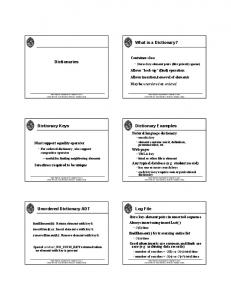
Figure 1. Top-level overview of the existing TOGAF model.
4.
Modeling tools, methods and strategies
To specify Catch’s business processes in the form of workflow diagrams, the Business Process Modeling Notation (BPMN) (Object Management Group 2006, White 2004) was chosen. BPMN is based on a flowcharting technique that is similar to activity diagrams from UML. Enterprise Architect (EA) (Sparx Systems 2010) by Sparx Systems was used as a modeling tool. EA supports different modeling languages such as UML, SysML and BPMN, and also has some support for model transformations. EA has a built-in scripting language that allows users to modify and extend its functionalities. All model data was managed using a central repository managed by a version control system.
4.1.
Initial process model
Catch already had an existing partial BPMN process model as part of the business architecture portion of their enterprise architectural model, which was based on The Open Group Architecture Framework (TOGAF) for enterprise information architecture (The Open Group 2009). This framework specifies an approach for the whole life cycle of the information architecture in an enterprise: from the planning and design stages to the implementation and the governance during operation. However, this initial business architecture portion of the TOGAF model was incomplete and used an incomplete process hierarchy.
November 3, 2013
18:32
8
Enterprise Information Systems
DayLutteroth
Taylor & Francis and I.T. Consultant
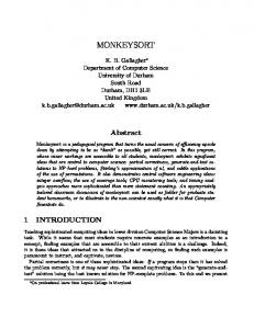
Figure 2. Illustration of the sparse structure of the Initial Process Model.
A top-level overview of the organization’s TOGAF model is shown in Figure 1. TOGAF allows an organization to incrementally improve its business by performing successive iterations around the TOGAF model. As can be seen in the figure, TOGAF subdivides the overall information architecture into seven phases, with requirements management playing a central role in each of the phases. After developing a high-level view in the architecture vision phase, the models become more concrete and detailed in the later phases. In the business architecture phase, a business process model is developed. And then in following two phases, the information architecture and technology to support the business process is specified. The TOGAF model explicitly recognizes the need for iterative change, as visible in the following phases that eventually lead back to the first phase. The aim of this project was to model the process information shown under phase B, business architecture. Figure 2 shows a portion of the existing process model contained in phase B. Just by looking at the overall structure of this model, it becomes clear that it is lacking a clear hierarchical structure: many process layers are only sparsely populated, and the process
November 3, 2013
18:32
Enterprise Information Systems
DayLutteroth
Enterprise Information Systems
9
Table 1. Workflow Model Layers Level
Layer
0 1 2 3 4 5
Business Capabilities Services Business Processes Processes Sub-Processes Tasks
elements are only loosely interconnected. Generally, the elements are scattered over the model hierarchy, so that the potential benefits of a hierarchical structure are not realized. One could argue that such a sparse model does not warrant the use of many layers. The potential benefits of using layers are twofold. First, layers may be used to distinguish semantic differences in the model, i.e. distinguish semantically different but interelated submodels. For example, a model may consist of interrelated layers for infrastructure, applications, and business processes in an organization (Jonkers et al. 2004). Second, layers may be used to represent different levels of abstraction, allowing users of the model to look at it at a particular level of detail. This is important for visualization in multiscale user interfaces (Furnas and Bederson 1995), which support techniques such as zooming or fisheye views. As explained in more detail later on, larger models such as the one created in this project benefit a lot from a multilayer approach. Modeling was performed using mainly two approaches. First, as much information from the previous BPMN model as possible was to be extracted and reused. It was clear that this would require a significant amount of restructuring work. After taking as much as possible from the existing model, the second phase of analysis and modeling would gather missing information and validate the process model. To achieve this, staff interviews were conducted. This process involved scheduling individual meetings with all of the staff members at Catch and asking them what they do, and then mapping each process with as much detail as possible.
4.2.
Supporting different layers of abstraction
At the beginning of the project, it was decided to split up all modeling efforts into different layers of abstraction, as listed in Table 1. This was important in order to manage the complexity of the numerous business processes and allow users of the model to look at business processes in different levels of detail. This means that users of the model can explore the business processes in a top-down manner without being drowned in the numerous details too early. Users can then drill down into the details of a particular process they are interested in. This approach also proved very valuable during modeling, as it allowed the modelers to gain an overview first before confronting the details. After mapping a few levels, an analysis was performed to estimate the total number of elements in the model on each of the levels and the zoom factor between the levels, i.e. the factor by which the size of a model is multiplied when drilling down into a lower, more detailed level. The results of this analysis, which were presented to all stakeholders, are presented in Table 2. It took approximately two months effort to have sufficient data
November 3, 2013
18:32
Enterprise Information Systems
10
DayLutteroth
Taylor & Francis and I.T. Consultant
Table 2. Forecast Element Totals Level 0 1 2 3 4 5
Business Capabilities Services Business Processes Processes Sub Processes Tasks
Core
Auxiliary
Total
8 42 160 640 ? ?
6 13 61 220 ? ?
14 67 220 860 500 5000
for these estimates. Process elements are categorized into core and auxiliary business capabilities; the former are offered as services to clients, whereas the latter are services that are only used internally. For the lowest levels, 4 and 5, it was not possible to create accurate estimates at this stage because the numbers of elements become very large. The total number of elements drops from estimated 860 to estimated 500 between the processes and sub-processes levels because not all the processes were decomposed into sub-processes, and some sub-processes were shared among the processes. As can be seen from the table, the “zoom factor” is approximately 4, i.e. for every element at any given level, on average you would find at least four elements that it encapsulates within the level below. This enabled us to estimate the size of the complete model. It also showed the importance of using different layers of abstraction: although the lowest layer contains the complete detailed process model, it would be extremely hard to gain an oversight just from this level. In our experience, providing a hierarchical decomposition makes understanding, searching, navigating, applying and creating the model much easier and allows achievable milestones to be set for the project team.
4.3.
Supporting different project management methodologies
A pattern started to emerge when the modeling process was carried out: in each of the “core” (client facing) business capabilities, there was a form of project management overarching the process model. There was also an underlying project management methodology used in the initial model that was crosscutting all the services that the business had to offer. As a result, it was decided to restructure the model from an ineffective activity database to a proper workflow that recognizes project management as an important crosscutting concern. This is also an important realization in terms of moving from level 2 to level 3 of the CMMI because CMMI level 3 characterizes an organization as having a strong project discipline. It also became apparent that it was a limitation to support only one type of project management methodology. Catch needed to be able to use different project management methodologies, e.g. some customers require Catch to incorporate their own project management methodology. This is consistent with the guidelines of CMMI level 3, where a generic standard process has to exist that can be tailored to the needs of individual projects. Hence, reflecting this possibility in the model was one of our biggest challenges in this project. Thus the strategy chosen to deal with this issue was to merge a Project Management Institute (PMI) workflow as a grouping mechanism into level 2 of our model (the business process layer). This workflow was adopted from the Guide to the Project Management
November 3, 2013
18:32
Enterprise Information Systems
DayLutteroth
Enterprise Information Systems
11
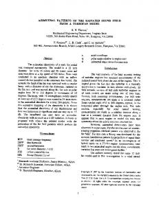
Figure 3. Key project attributes and project methodologies.
Body of Knowledge (PMBOK) (Institute of Electrical and Electronics Engineers 2003), which is a process-based, internationally recognized standard of project management essentials. It was suggested that the PMI framework could be implemented as a grouping layer into the overall process model, so that in the future, the project management components could readily be reused and grouped in a different form within the model to enable the representation of other methodologies, e.g. PRINCE2.
4.4.
Supporting different software development processes
In addition to supporting different project management methodologies, there was the need to support different software development processes. Many of Catch’s projects are centered on improving the efficiency of organizations that require software in their organizational processes, or develop software themselves. The reasons for this requirement were similar to the ones mentioned for the project management methodologies. In the model, software development processes would be situated under the execution phase of the PMI, in the business process layer. This is where eight stages of a typical Systems Development Life Cycle (SDLC) were modeled, which could be configured in more detail in the layers below. Again, this degree of customizability is consistent with the idea of a customizable standard process in the CMMI level 3 requirements. It is Catch’s belief that each project has different characteristics, and that these characteristics lead to projects being executed in different ways. For example, a project that has a high risk and is more focused on R&D may be better suited to run using an agile methodology, whereas a project with flexible costs that is looking for a high quality output may be more suited to run using a more predictive methodology. Figure 3 shows the relationship between key project attributes and the project methodology that would be used to implement it, as seen by Catch. If a customer’s project was cost and time critical then a waterfall project would be used, while if cost and quality were critical to the project’s success then an agile methodology would be utilized. To keep the software development process flexible while providing a model for software development, the Rational Unified Process (RUP) (Barnes 2007) was chosen. RUP is not a single software development process, but a process framework, which means that it can be adapted to different needs, resulting in different concrete development processes. For example, RUP can be customized to a waterfall-style process model, but it can equally
November 3, 2013
18:32
Enterprise Information Systems
12
DayLutteroth
Taylor & Francis and I.T. Consultant
be customized to an agile process (McCormick 2001) along the lines of Extreme Programming (XP) (Beck and Andres 2004). Materials on RUP were abundant and readily available. RUP has been well tested and is utilized by numerous global organizations.
5.
Results
The project had a number of interesting results. Some were mostly useful during the modeling process itself, while others emerged after the project. Besides the outcomes traditionally associated with CMMI level 3, there were some long-term impacts that deeply affected the company, and are probably the most important results altogether. In the following, the different results are explained.
5.1.
Results during the project
There were several problems that had to be faced during this project. The reuse of the existing TOGAF embedded process model proved difficult as the model was inconsistent and had little structure of the aforementioned layers of abstraction. The categorization and transition of the various elements from the initial TOGAF encapsulated process model into the new six-layered model was time consuming and illustrates the importance of a proper modeling strategy. Such a strategy has an immediate impact on the quality of the resulting model and the possibilities of reuse. About 6 weeks effort were spent on extracting information from the initial model, and approximately 150 model elements could be extracted and reused in the new model. The interviews went reasonably smoothly, and it was possible to extract many of the activities, processes, and workflows that were performed by the staff. However, there were two common problems. On the one hand, extracted information was sometimes given on a rather low level of abstraction, i.e. on the level of detail that an activity was actually performed by a person. This meant that the modelers had to analyze and construct the higher levels by themselves by grouping the elements of the lower levels. On the other hand, extracted information was often missing important details as theses details had been internalized through routine by the people who performed the activities. Thus, people were not so aware of them anymore and typically did not convey the information during the interviews. This meant that the modelers had to spot and fill the gaps either by applying best practices or by getting back to the interviewees. In total, 7 people were interviewed. Each person was interviewed between 3 and 5 times, with each interview between 30 to 60 minutes long. All of the models were validated using peer reviews. Each model area was reviewed by both modelers and one or two senior staff members. In most of the cases (estimated 50% to 70%) the models were created correctly the first time. The problems were mostly due to ambiguities in the model that had to be resolved; not so much due to ambiguity in the information extracted from the interviews. It was not immediately clear that a project management workflow was a top-level crosscutting concern in the business process model. The first signs of the commonalities between the core processes became evident after about two weeks into the project, and after about six weeks it was clear that a lot of time and effort could be saved by taking these commonalities into account explicitly. The strategy to model project management as a crosscutting concern was a success: it gave a lot more structure to the process model, and made the top level processes easier to understand.
November 3, 2013
18:32
Enterprise Information Systems
DayLutteroth
Enterprise Information Systems
13
Figure 4. Part of the incomplete first RUP modeling attempt by role.
5.1.1.
Model structure
The main problem when modeling the development process part of the model was the discrepancy between the initial SDLC approach and RUP. The first attempt of combining these two approaches resulted in an SDLC framework containing RUP roles. Figure 4 illustrates the general structure of the model: it looks like a lane that contains a number of processes that are performed by a role, but does not give the user any idea of the actual timings or deliverables created from each process. Neither did this capture the iterative workflow of RUP, nor did it allow users of the model to understand the triggers for each of the process elements because those elements were modeled within other RUP roles. The figure shows part of the workflow for a systems analyst. Although the model contains the tasks that have to be performed by the analyst, it is not clear where an analyst actually starts performing these tasks. Similarly, at the bottom one can see deliverables produced by a system analyst, but it is not clear when these are produced and what happens to them next. Pulling the tasks and deliverables of the system analyst role out of its context and its relations to other roles reduces the usefulness of the model for the company significantly. Any given RUP role should have been involved in processes from different parts of the SDLC; hence the modeling of the process along the concept of RUP roles did not establish a proper workflow. Although the roles had been properly mapped, the model gave a fragmented overview of the roles rather than their activities over time. In the end it was decided to drop the SDLC structure of the development process model in favor of a purely RUP based model. The enormous size of RUP meant a much larger workload when integrating it into the process model. On the higher levels, the development process activities were grouped according to the four RUP phases: Inception, Elaboration, Construction, and Transition. After this was completed, it was easy to see and follow through the lower levels of the entire model using hierarchical decomposition. By the end of the project, just over 850 elements within the RUP had been mapped, not including the various artifacts and
November 3, 2013
18:32
Enterprise Information Systems
14
DayLutteroth
Taylor & Francis and I.T. Consultant
Figure 5. Structural overview of the initial RUP inception phase model without layering. The numerous long connections make the model illegible.
classification of the various roles associated with the mapped elements. RUP is very complex and contains a large number of elements, therefore its visual specification proved a big challenge. As illustrated in Figure 5, the process model diagrams soon became so saturated with model elements that they started looking like circuit diagrams with large buses of connections running through them, even after only the conception phase had been modeled. The diagram correctly specifies the process flows, and can be used to look up the triggers for each process. However, people found it extremely difficult to follow the numerous connectors; therefore the modeling attempt was deemed unmanageable. This confirms the common observation that visual models frequently suffer scalability problems (Buckl et al. 2007). The solution to this problem was the increased use of hierarchical decomposition within the RUP model, i.e. parts of the RUP workflow were grouped into higher-order process elements.
5.1.2.
Coverage
Table 3 shows the estimated coverage of the modeling project. On the upper layers modeling was completed, whereas the lower layers are still lacking many details. For some areas from the core services such as the software development processes, the model provides good coverage. However, other areas such as finance, human resources and marketing need further modeling and the application of recognized best practices. Since they are auxiliary services, they were considered secondary during our modeling work. When it comes to the details of the processes used in these areas, the company has started to document these but at present relies primarily on expert knowledge from individual staff.
November 3, 2013
18:32
Enterprise Information Systems
DayLutteroth
Enterprise Information Systems
15
Table 3. Overview of modeling coverage
5.2.
Level
Core
Auxiliary
Total
0 1 2 3 4 5
100% of 8 100% of 42 50% of 160 50% of 800 13% of 460 20% of 5000
100% of 6 100% of 13 100% of 61 30% of 220 5% of 100 0% of 1000
100% of 14 100% of 67 64% of 220 46% of 1020 12% of 560 16% of 6000
Business Capabilities Services Business Processes Processes Sub Processes Tasks
Results immediately afterwards
As a result of the modeling effort, important parts of the organizational processes were documented. This is useful as a general day to day reference of how things are done at Catch. If a person has not done a particular activity before, that person can read up on the process using the model. Of course, this does not replace proper training and experience, but it helps the company to function better nevertheless. The process model also ensures a higher degree of consistency and repeatability. Without a process model, the way processes are done would inevitably vary due to lack of process knowledge, or due to uncertainty and misunderstanding. Although such variance cannot be eliminated, e.g. due to differences in skills, a process model sets a standard that helps to keep all activities on track. Last but not least, the process model helps with the organizational training program. With a clear process specification, training can be more formal. Also, it is easier to assure a good coverage of the activities in the company during training.
5.3.
Long-term impact on the company
Before the project, and also for a while after the project was finished, Catch had a number of services, including resourcing, consulting, mentoring and training. There are big differences between the profits that each of these services yeilds. Especially for a small company, it can be a challenge to manage a multitude of services, rather than focusing on a smaller number of services that are profitable. Without an enterprise model, it is hard to keep a clear oversight of the different services. So once such a model was established, an analysis of the company with regard to its services becase more feasible. The modeling project itself proved to be also an introspective exercise, helping Catch to understand better where its opportunities lie. This new understanding of the company led to a significant restructuring effort. Catch is moving away from low-profit services such as resourcing, towards higher-profit services such as training. In the past year, Catch also managed to establish a new revenue stream by bringing the test management tool Enterprise Tester (Day and Lutteroth 2010) to market. With its two tools, Screen Architect and Enterprise Tester, Catch is moving further into the software tools market. If Catch’s tools business keeps growing, it is to be expected that Catch can also grow its training business to meet the demand for support in the tools’ user base. This is consistent with the suggestion of Khurshid et al. (2009) that CMMI adoption efforts should be considered as investments rather than simply a process improvement
November 3, 2013
18:32
Enterprise Information Systems
16
DayLutteroth
Taylor & Francis and I.T. Consultant
Figure 6. Example process and linked template.
technique. In the case of Catch, these efforts did not result in a full adoption of CMMI level 3, but are now paying off in terms of revenue.
6.
Future work
The new process model serves as a foundation for future extensions, improvements and applications. In order to reach CMMI level 3, a process group needs to be established that oversees further development and maintenance of the model. For some areas the details in the lower layers of the model are still missing, but due to the top-down approach all areas are already mapped out in some detail. Because the model is kept in a central repository that can be accessed by all staff, process information can be searched and retrieved on demand. In the lower levels, the process model contains links to forms and report templates, which are also stored in the repository. This is illustrated in the screenshot in Figure 6, which shows a part of the process model in the back, and an associated form and report template in the front. As a result, the model has the potential to become a living part of Catch’s operational infrastructure. This leads to research questions as to how process models can be effectively used in organizations and how this can be supported by software tools. Furthermore, it would be useful to know how tools supporting the application of a process in an organization could best be extended to support an organizational measurement program, as suggested in CMMI level 4. As explained in Section 4 and specified in CMMI level 3, the process model has to
November 3, 2013
18:32
Enterprise Information Systems
DayLutteroth
Enterprise Information Systems
17
offer certain degrees of flexibility so that it can be adapted to the needs of individual projects. One could envision an automated process customization system that lets project managers choose different process parameters such as project size, a project management methodology and a software development process. For example, users may choose between a PRINCE2 (Office of Government Commerce 2005) project management methodology in favor of PMI, or a more traditional waterfall process model vs. an agile development process, depending on the project requirements. Although some tools like this exist for particular process frameworks such as RUP, it is unclear how such a tool could support the customization of generic processes in general. Such a tool would need to support the definition and instantiation of parameterized processes. In the area of programming languages there is a long tradition of research into genericity and reuse, and some of the approaches might become more popular in the world of business process definition, e.g. concepts for aspect-oriented process definition and process weaving. With a repository of process definitions, combined with quantitative measurements of current and historic projects, automatic creation of useful project estimates may become feasible. A process support tool could potentially generate documents such as a project schedule based on these measurements, or even a full project proposal. For this to work, we need a better understanding of how to relate quantitative measurement data to process models such as those specified with BPMN, and how such data can be used effectively.
7.
Conclusion
During the three months of this project, a business process model for an ICT consultancy company was created. The model does not cover all the process areas in every detail, but specifies all important activities, at least, on a higher level of abstraction. This brought Catch significantly closer to level 3 of the CMMI maturity model. Our experience from this project shows that to successfully and efficiently implement a business process model, upfront planning and proper tools, methods and strategies are required. While the planning and the tools have an immediate impact on the efficiency of the modeling process itself, the methods and strategies also have a significant impact on the usefulness of the created model. In particular, the following problems have been identified: • Visual models have inherent scalability problems that can be mitigated by using different levels of abstractions, e.g. through hierarchical decomposition. • Business process models can contain crosscutting concerns such as project planning methodologies or software development processes, which have to be identified and modeled explicitly to avoid bloated and hard-to-understand models. • Tool support for creating and managing large models is very important, and clear model visualization needs further improvement. • Tool support for the customization and instrumentation of processes would be useful for organizations on higher CMMI maturity levels, e.g. in the form of parameterized process models. Further research into these problems could make future modeling efforts easier, and help organizations to use business process models more effectively. Looking at the outcomes of the modeling project for Catch, it becomes clear that the benefits may be manifold. A well-specified process model serves as a reference, helps to establish and streamline an organizational training program, and reduces variance in the
November 3, 2013
18:32
Enterprise Information Systems
18
DayLutteroth
REFERENCES
way processes are performed. At the same time it is an introspective exercise that can guide the evolution of an organization, similar to the iterative cycles described by the TOGAF model. In the case of Catch, it lead to a significant restructuring of the company and an improved revenue stream.
References Anderson, D., 2005. Stretching agile to fit CMMI level 3. In: Proceedings of the Agile Development Conference (ADC 2005) IEEE. Baker, S., 2005. Formalizing agility: an agile organization’s journey toward CMMI accreditation. In: Proceedings of the Agile Development Conference (ADC 2005) IEEE, 185–192. R and solutions: a Barnes, J., 2007. Implementing the IBM Rational Unified Process guide to improving your software development capability and maturity. IBM Press. Beck, K. and Andres, C., 2004. Extreme programming explained: embrace change. Addison-Wesley Professional. Buckl, S., et al., 2007. Generating Visualizations of Enterprise Architectures using Model Transformations. EMISA 2007, 33–46. Chrissis, M., Konrad, M., and Shrum, S., 2003. CMMI Guidlines for Process Integration and Product Improvement. Addison-Wesley. Day, B. and Lutteroth, C., 2010. Enterprise Tester - A Model Driven Testing Project. In: Proceedings of the 21st Australian Software Engineering Conference (ASWEC 2010). Deloitte, 2008. Deloitte/Unlimited Fast 50 Index. Available from: http://www.deloitte.com/. Furnas, G. and Bederson, B., 1995. Space-scale diagrams: Understanding multiscale interfaces. In: Proceedings of the SIGCHI conference on Human factors in computing systems, 234–241. Garcia, S., 2005. Thoughts on applying CMMI in small settings. Software Engineering Institute. Gartner, 2001. Describing the Capability Maturity Model. MeasureIT. Institute of Electrical and Electronics Engineers, 2003. IEEE Standard 1490 - 2003 Adoption of PMI Standard - A Guide to the Project Management Body of Knowledge. IEEE. Jonkers, H., et al., 2004. Concepts for modeling enterprise architectures. International Journal of Cooperative Information Systems, 13 (3), 257–287. Khurshid, N., Bannerman, P., and Staples, M., 2009. Overcoming the First Hurdle: Why Organizations Do Not Adopt CMMI. Trustworthy Software Development Processes., 38–49. McCormick, M., 2001. Technical opinion: Programming extremism. Communications of the ACM, 44 (6). Object Management Group, 2006. Business Process Modeling Notation Specification. OMG. O’Connor, R.V. and Coleman, G., 2009. Ignoring” Best Practice”: Why Irish Software SMEs are Rejecting CMMI and ISO 9000. Australasian Journal of Information Systems, 16 (1). Office of Government Commerce, 2005. Managing Successful Projects with PRINCE2 Manual 2005. TSO. Paulk, M., et al., 1995. The capability maturity model: Guidelines for improving the software process. Addison-Wesley.
November 3, 2013
18:32
Enterprise Information Systems
DayLutteroth
REFERENCES
19
Pikkarainen, M. and M¨ antyniemi, A., 2006. An approach for using CMMI in agile software development assessments: experiences from three case studies. In: SPICE 2006 conference, Luxemburg, 4–5. Sparx Systems, 2010. Enterprise Architect. http://www.sparxsystems.com/products/ea/. The Open Group, 2009. TOGAF Version 9 - The Open Group Architecture Framework. Document G091. Tosun, A., Bener, A., and Turhan, B., 2009. Implementation of a Software Quality Improvement Project in an SME: A Before and After Comparison. In: Proceedings of the 2009 35th Euromicro Conference on Software Engineering and Advanced Applications IEEE Computer Society, 203–209. White, S., 2004. Introduction to BPMN. Business Process Trends. Wilkie, F.G., McFall, D., and McCaffery, F., 2005. An Evaluation of CMMI Process Areas for Small- to Medium-sized Software Development Organizations. Software Process Improvement and Practice, (10), 189–201.