The goal of hearing aids is to selectively attenuate acoustic signal based on the directional of sound arrival. Directional microphone or microphone arrays are ...
CMOS compatible directional microphone Po-Hsun Sung*, Jen-Yi Chen, Kai-hsiang Yen, Chia-yu Wu South Branch/Industrial Technology Research Institute 195-4, Sec. 4, Chung Hsing Road Chutung, Hsinchu Taiwan, R.O.C.
ABSTRACT The goal of hearing aids is to selectively attenuate acoustic signal based on the directional of sound arrival. Directional microphone or microphone arrays are used to achieve this goal. The longer distance of microphone pairs is a problem of the application on hearing aids. In this paper, a single directional microphone structure is proposed to solve this problem and can be used in other application. This directional microphone is constructed by the post CMOS MEMS process. The mechanism of this structure is originally inspired the by the ears of fly Ormia ochracea. In the result, the characteristic of this directional microphone is bi-direction pattern.
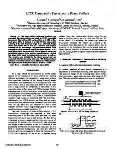
thin structure. The two tympana is connected by this thin structure. It is call intertympanal bridge, expressed as K3,C3 in Fig 1. In this model, the two tympana are taken as corrugated membranes witch are connected with intertympanal bridge and to the tympanal pits. The tympanal pits are connected to boundary with springs and dampers. Those could be expressed as K1,C1 and K2,C2 in Fig 1.
INTRODUCTION In order to meet the need of single microphone with directional characteristics, the novel acoustic sensor for sound and vibration is developed by R. N. Mile[1]. The biomimetric diaphragm of directional microphone is inspired by the efforts at the understanding of the directional hearing mechanism of small animals such as insect. This approach is founded by the analysis of the coupled ears of the parastoid fly, Ormia ochracea. The mechanically coupled ears of Ormia ochracea have been shown to respond in two resonant modes of vibration, one in which is rocking mode and another is translational mode. In the following, the directional microphone structure is designed to sense the acoustic wave by the mechanism of coupled ears of Ormia ochracea. It is fabricated by the post CMOS process. The motion of structure is measured by the laser Doppler vibrometer.
BACKGROUND In the conventional directional microphone with two inlet port, the net pressure is proportional to the frequency of the sound, and thus has a 6dB per octave slope. The net pressure is also diminished with the reduction of the distance between two ports. In addition to, the reduction of diaphragm size is also proportion to the loss of sensitivity. The problem of electronically compensating for the 6 dB per octave slope of the diaphragm response results a substantial degradation in noise performance. In this reason, hearing aid manufactures must incorporate switches on hearing aids that allow user to switch to a omni-directional microphone mode in quiet environment, and to a directional microphone in noise environment.[2] In order to resolve the problem as above, a new concept of directional microphone is inspired by the discover of the ears of the parastoid fly, Ormia ochracea [3]. It is able to sense the directional of an incident sound wave. An equivalent model of the ears of Ormia ochracea is constructed in order to simulate the mechanical response when sound is from any incident direction [1]. Although two eardrums are very close, the vibration amplitude of tympanum which is closer to the sound source is greater than other. The difference in mechanical response is form the coupling of the ear’s motion by a
Fig 1. The ears of Ormia ochracea and a mechanical model which is used to describe the directional sensing diaphragm structure [2]
MICROPHONE DESIGN AND CONSTRUCTION In order to facilitate the structure design, it is necessary to estimate the acoustic sensitivity of the diaphragm. For simplifying the motion of diaphragm, the tympana diaphragm is assumed as an idea rigid body. The response of structure is dominated by the rocking mode. The plane motion of the diaphragm can be calculated by applying the momentum of a plane acoustic wave. It is incident at an angle Φ relative the normal direction of diaphragm. The structure can be simplified with lumped parameter model[4]. The sensitivities of Ormia directional microphone and conventional microphone can be calculated as follows, the structure schematic is shown in Fig2.
Ormia Sensitivity ≈
Vbias iω cos(φ ) sL 2 2 h ω1 + iω 2ω1ζ 1 − ω mc
Conventional Sensitivity ≈
(1)
Vbias iω cos(φ ) sα 2 d h ω02 + iω 2ω0ζ 0 − ω 2 mc
(2)
Where h is backplate gap, L is center distance of diaphragm, d is distance separated by the two ports, c is the sound speed, s is diaphragm area, αis geometry factor, ω 1andω 0 are the resonant frequencies of the Ormia directional and conventional microphone. Φ Φ
d
L
(a)
(b)
Fig 2. The simply schematic of (a) an Ormia ochracea directional diaphragm and (b) a convection gradient diaphragm.
The predicted acoustic responses are shown in Fig 3. The Ormia directional microphone has substantially higher sensitivity than conventional microphone. The reason is that the resonant frequency of rotational mode is designed around 1KHz. By the addition of critical damping, the resonance of frequency response becomes smoother.
RIE etch
M4 M3 M2 M1 P2 P1
Si substrate (b)
M4 M3 M2 M1 P2 P1
ICP etch Si substrate (C) Fig 3. An objective frequency response of CMOS directional microphone structure compared with conventional directional microphone. In order to achieve this goal, a rectangular diaphragm with supporting a rotational axis is constructed in this paper. The diaphragm size of directional microphone is 840um x 410um. It is composed of metal 1 to metal 4 layer in TSMC 035 2P4M CMOS structure. The size of center support beam is 20um x 440um and is at the center of diaphragm. It support as a rotational beam in this structure and fixed two end on the boundary. In initial design, we hope the resonant frequency of rotational mode is around 1 KHz and resonant frequency of translational mode is above 20 KHz. Owing to the material characteristic and limitation of CMOS layer, the structure is designed to rotate at 8 KHz and translate at 13 KHz. In the future, the resonant characteristics could be modified by the change of supporting boundary conditions.
Fig 4. A process flow of CMOS directional microphone structure. In the fabrication of microphone, the influence of stress and stress gradient are important factors. According to the result of theoretical modeling, it can be known that residual stress has a significant impact on the mechanical sensitivity of a diaphragm in an acoustic transducer. Under the influence of the residual stress, the supporting conditions of the diaphragm must be designed or a folding structure must be formed, so as to enhance the mechanical sensitivity of the diaphragm. In addition, the residual stress gradient will induce the deformation of released structure. The simulation result is shown in Fig 5. In order to increase the effectiveness of capacitive sensing, the curl matching frame is added in the outer of structure.
A directional microphone structure has been integrated on chip by a high spec ratio CMOS micromaching. It is fabricated by two ploy four metal 0.35um TSMC CMOS process. After this foundry fabrication, two dry etch steps, shown in, are used to define and release the structure. The top metal layer of CMOS structure is taken as a etching mask for forming cavity. In first step, the dielectric layer is removed by anisotropic etching with CH3/O2 reactive ion etch (RIE), as shown in Fig. 4(b). In the second step, the silicon substrate is removed by the backside etching with C4F8/SF6/O2 inductively coupled plasma (ICP) until the silicon oxide layer, as shown in Fig. 4(c). Finally, the structure is fully released as shown in Fig.4 (c). M4 M3 M2 M1 P2 P1
Si substrate (a)
Fig 5. The deformation of 1st CMOS directional microphone structure with residual stress gradient is simulated.
EXPEREMENTAL RESULTS In the 1st CMOS directional microphone design, the concept of zaxis accelerometer structure is used to build up the compatible structure. The structure is shown in Fig 6, the disadvantages of this structure are non flatness and sensitive to vibration. In order to improve the characteristic, a membrane with rib structure is used to increase the stiffness of structure and decrease the mass of membrane. The rib type of metal layer is pre layout on CMOS chip, then the rib structure below the membrane has been formed by the post CMOS micromaching process. The 2st CMOS directional microphone without comb electrode structure is shown in Fig 7.
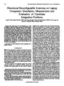
In the Fig. 8, we compare the flatness of 1st and 2 st CMOS directional microphone. It is shown that the 2 st CMOS directional microphone with rib structure is flatter than 1 st. Another advantage of this structure is the reduction of mass. In our simulation, the sound pressure 1Pa loading induce the maximum deformation is 7.661e-2 um and Z axis volume acceleration 1G loading results in the maximum deformation is 3.109e-4 um. The structure is insensitive to the vibration noise. Besides, in order to test the directional polar pattern of 2 st CMOS directional microphone, the experimental equipment is set up like Fig. 10. The directional microphone is measured using a commercial laser Doppler vibrometer (LDV) system. The speaker is set up to tuning the sound incident angle. In experience, the radiation absorbent material is set around the microscope to reduce the acoustic noise. The rocking mode resonant frequency of 2 st CMOS directional microphone is at 8.4 kHz. In rocking mode, the maximum deformation of diaphragm is measured with different incident angle. It shows the polar pattern of diaphragm is like bi-direction, as shown in Fig. 9. Directional sensitivity at 8.4KHz 0 330
30
1E-7 300
Fig 6. The structure of 1st CMOS directional microphone structure is released by the post CMOS process
1E-8
60
270
90
240
120
1E-7
840 um
410 um
210
150 180
Fig 9. The directional polar pattern of 2st CMOS directional microphone structure. Fig 7. The structure of 2st CMOS directional microphone structure is released by the post CMOS process
Fig 10. The experimental setup for measuring the directional polar pattern of the diaphragm. Fig 8. The flatness of CMOS directional microphone structure
ACKNOWLEDGEMENT The author would like to thank Chih-ming Sun and Professor W. Fang of the Power Mechanical Engineering, National Tsing Hua University for the measurement of WYKO. This research is supported by the ITRI Advanced Project 6301XSW810.
REFERENCE [1]
[2]
[3]
[4]
R. N. Miles, D. Robert, and R. R. Hoy, "Mechanically coupled ears for directional hearing in the parasitoid fly Ormia ochracea," Journal of the Acoustical Society of America, vol. 98, p. 3059, 1995. R. N. a. R. R. H. Miles, "The development of a biologically-inspired directional microphone for hearing aids," Audiology & Neurotology, vol. 11, pp. 86-94, 2006. D. Robert, "Innovative Biomechanics for Directional Hearing in Small Flies," Biol. Bull, vol. 200, pp. 190-194, April 2001. L. Tan, R. N. Miles, M. G. Weinstein, R. A. Miller, Q. Su, W. Cui, and J. Gao, "Response of a biologically inspired MEMS differential microphone diaphragm," in Unattended Ground Sensor Technologies and Applications IV, Apr 2-5 2002, Orlando, FL, United States, 2002, pp. 91-98.