CMUT With Substrate-Embedded Springs For Non-Flexural Plate Movement Amin Nikoozadeh and Pierre T. Khuri-Yakub, Stanford University, Stanford, CA e-mail:
[email protected] Abstract — A conventional capacitive micromachined ultrasonic transducer (CMUT) is composed of many cells connected in parallel. Since the plate in each CMUT cell is anchored at its perimeter, the average displacement is several times smaller than the displacement of an equivalent ideal piston transducer. In addition, the post areas, where the plates are anchored to, are non-active and, thus, do not contribute to the transduction. We propose a CMUT structure that resembles an ideal capacitive piston transducer, where the movable top plate only undergoes translation rather than deflection. Our proposed CMUT structure is composed of a rigid plate connected to a substrate using relatively long and narrow posts, providing the spring constant for the movement of the plate. Rather than the flexure of the plate as in a conventional CMUT, this device operates based on the compression of the compliant posts. For a capacitive transducer, a thin electrostatic gap is provided under the top plate. We used finite element analysis (FEA) to design and verify the structure’s functionality. The simulation results show a fractional bandwidth of over 100% in immersion for all the designs. They also confirm that the average displacement of the top plate is above 90% of its peak displacement. We fabricated the first prototype based on this idea, which only requires a simple 3-mask fabrication process. In addition to 128element 1-D arrays, we fabricated a variety of 240 µm × 240 µm, single-element transducers with different post configurations. We successfully measured the electrical input impedance of the fabricated devices and confirmed their resonant behavior in air. Further, we measured the acoustic pressure using a calibrated hydrophone at a known distance. Using this measurement, we calculated a peak-to-peak pressure of 1.5 MPa at the face of the transducer.
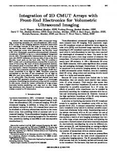
vacuum gap forming a capacitor. One of the electrodes resides on a stiff substrate and the other electrode is formed on or as part of a flexible plate. The plate is anchored around its perimeter to fixed posts (Fig. 1).
Figure 1. Conventional CMUT cell.
During operation, a DC bias is applied across the two electrodes causing the top plate to deflect towards the bottom electrode. Since the top plate is anchored around the edges, its center undergoes the maximum deflection. For a typical circular CMUT cell, the center displacement before the pull-in point is approximately 0.41 times the effective gap height [1]. The average displacement of the plate, however, is only about 0.13 times the gap height [1]. For an ideal electrostatic piston transducer, the plate displacement before the pull-in is onethird of the gap height. Therefore, for the same gap height, the average plate displacement of a conventional CMUT is approximately 2.6 times smaller than the displacement of a piston transducer. Additionally, the post areas, where the CMUT plate is anchored to, do not contribute to the overall average displacement of the whole CMUT element. Therefore, for a CMUT element, the average displacement would be even further smaller than the displacement of an ideal piston transducer.
Our results show that it is possible to fabricate CMUTs that exhibit ideal piston-like plate movement. Because of the substrate-embedded spring elements, the plate does not need to be operated in flexural mode, as in a conventional CMUT, resulting in a significantly improved fill-factor, and, thus, a more efficient device.
In this paper, we propose a CMUT structure that resembles an ideal piston transducer. We present FEA simulation results and the experimental results of the first fabricated prototype.
Keywords – ultrasound; capacitive micromachined ultrasonic transducers; CMUT; piston transducer
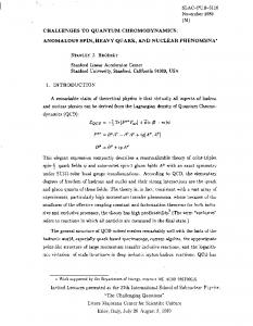
A. Proposed Device Structure We propose a CMUT structure that is composed of a rigid top plate connected to a substrate using a compliant post structure. Rather than the flexure of the plate as in a conventional CMUT, this device operates based on the compression of the compliant posts. The top plate transfers any exerted pressure to the posts. The compression and relaxation of the post structure is then reflected in the translational
I.
INTRODUCTION
A conventional CMUT element is composed of several cells that are connected in parallel. The basic structure of a CMUT cell consists of two electrodes that are separated by a
II.
METHODS
movement of the top plate. The posts may simply be a plurality of cylindrical rods that provide the spring constant for the movement of the plate. For a capacitive transducer, a thin electrostatic gap is provided under the top plate (Fig. 2).
is the Young’s Modulus of the post. Therefore, if the stress applied at the rod is T, the strain, S, can be calculated using: T = ES ,
(1)
where E is the Young’s Modulus of the post’s material. Replacing for the stress and strain terms, one can find the relationship between the force, F, and the displacement, x, using: F=
E × A post h post
x,
(2)
where Apost and hpost denote the cross-sectional area and height of the post, respectively. Therefore, the spring constant can be expressed using: k= Figure 2. Proposed CMUT structure (one unit cell is shown).
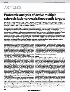
Similar to a conventional CMUT, a DC bias is applied across the electrostatic gap during the operation of the device. However, the electrostatic force in this case causes the posts to compress, which results in the substantially vertical translation of the top plate. Additionally, the non-active areas in the conventional CMUT do not exist in the proposed structure, which results in a significantly larger fill-factor. The unit-cell shown in Fig. 2 is part of a whole transducer element that is composed of a plurality of posts. A 2-D array element representation of the proposed device is shown in Fig. 3.
E × A post h post
.
(3)
It is seen from this expression that the spring constant is inversely proportional to the height of the post and it is proportional to the cross-sectional area of the post. Assuming that the total mass of the structure is mostly dominated by the mass of the top plate, mplate, one can calculate the open-circuit resonant frequency of the structure using: f0 =
1 2π
k . mtotal
(3)
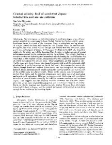
C. Finite Element Analysis We performed FEA simulations using ANSYS (ANSYS, Inc., Canonsburg, PA) for the unit-cell shown in Fig. 2 to verify the functionality of the proposed CMUT structure. By changing the device parameters, such as the post diameter, post height, plate diameter, etc., we simulated a variety of designs in the range of 4-40 MHz. The simulation results all show a fractional bandwidth of over 100% in immersion. They also confirm that the average displacement of the top plate is above 90% of its peak displacement. Table I shows the device parameters for one of these designs. The corresponding simulated acoustic frequency spectrum is shown in Fig. 4. D. Fabrication We fabricated a variety of devices based on this idea, including 128-element 1-D arrays and 240 µm × 240 µm single-element transducers with different post configurations.
Figure 3. 3-D prospective view of a 2-D element.
B. Simple Theory Using the unit-cell shown in Fig. 2, one can derive simple first-order expressions for the spring constant of the post and the resonant frequency of the structure. Assuming that the top plate is significantly more rigid than the post, the spring constant of the structure is solely determined by the spring constant of the post. Hooke’s law states that the stress and strain in a material are proportional with the proportionality factor being the elastic constant of the material. In the case where the post is a thin rod the relevant coefficient of elasticity
The simple 3-mask fabrication process started with a lowresistivity silicon wafer (Fig. 5). We oxidized the wafer and patterned the oxide to define the vacuum cavities. We then etched deep ring-shape trenches in the silicon substrate using deep reactive ion etching to define the cylindrical posts. We then bonded the wafer to another oxidized SOI wafer using the high-temperature assisted direct bonding process and removed the SOI wafer’s handle and box layers. Finally, we sputtered aluminum and patterned both the aluminum and the silicon top plate. The fabrication process described here uses many of the steps involved in fabricating conventional CMUTs [2, 3]. Fig. 6 shows the SEM of the posts for one of the fabricated devices. Since the operation of the proposed device relies on
the compliant post structure, the device uniformity is highly dependent on the quality of the fabricated high aspect ratio posts. A fabricated 128-element 1-D array with an element pitch of 200 µm is shown in Fig. 8. TABLE I.
DEVICE PARAMETERS FOR A HIGH-FREQUENCY DESIGN
Parameter
Value
Post diameter (µm)
3
Post height (µm)
35
Post pitch (µm)
10
Plate thickness (µm)
1
Vacuum gap (nm)
50
Pull-in voltage (V)
46
Figure 6. SEM of the posts for a fabricated device (cross-sectional view, debris from polishing).
Figure 4. FEA simulation of acoustic pressure for the design in Table I.
Figure 7. Photograph of a fabricated 128-element 1-D array.
III. (a)
(b)
(c) Figure 5. Fabrication Process. (a) Oxidize a prime silicon wafer and pattern the oxide. (b) Etch deep trenches into the silicon to from the posts. (c) Directbond an oxidized SOI wafer and remove the handle and box layers. Deposit aluminum and pattern the aluminum (and the top plate).
RESULTS
We performed a variety of measurements for the test singleelement transducers (240 µm × 240 µm). The electrical input impedance measurements in air confirmed the resonant behavior of the fabricated devices. We also measured the acoustic pressure performance in oil using a calibrated hydrophone (Model HNV-0400, Onda Corporation, Sunnyvale, CA). Table II shows the design parameters for one of the fabricated devices. We biased this device at 40 V and applied a short unipolar 70-V pulse using a high-voltage pulse generator (Panametrics Model 5055PR, Panametrics, Inc., Waltham, MA). We measured the acoustic pressure using the calibrated hydrophone at 3 mm distance. Fig. 8 shows the measured pressure after normalizing with the hydrophone sensitivity. Even though not corrected for the attenuation losses in the oil, we measured a fractional bandwidth of 137% around the center frequency of 9.1 MHz, which demonstrates the wideband behavior of the proposed structure. After correcting for diffraction and attenuation losses, this measurement corresponds to a peak-to-peak pressure of 1.5 MPa at the face of the transducer.
TABLE II.
DESIGN PARAMETERS FOR A FABRICATED DEVICE
Parameter
Value
Post diameter (µm)
5
Post height (µm)
65
Post pitch (µm)
30
Plate thickness (µm)
10
Vacuum gap (nm)
170
simulate the behavior of the device. We are specifically working on models that emulate the fabricated test devices as closely as possible to compare the simulations with the measurement results. We are also continuing the characterization of the fabricated test devices. Among other experiments, we will perform areal scans of the top plate using a laser interferometer to experimentally assess the degree of translational movement of the top plate. V.
CONCLUSIONS
The preliminary simulation and experimental results of our proposed structure show that it is possible to fabricate CMUTs that exhibit ideal piston-like plate movement. Because of the substrate-embedded spring elements, the top plate does not need to be operated in flexural mode, as in a conventional CMUT. Additionally, the non-active plate anchor areas in a conventional CMUT do not exist in the proposed structure, which results in a significantly improved fill-factor, and, thus, a more efficient device. Furthermore, the proposed structure provides more design flexibility as it substantially separates the mass and spring components of the transducer. (a) ACKNOWLEDGMENT This work was funded by the National Institutes of Health under grants NHLBI 5R01HL067647, USA and 5R01CA134720, USA. Fabrication was done at the Stanford Nanofabrication Facility (Stanford, CA), which is a member of National Nanotechnology Infrastructure Network. We would like to thank Xuefeng Zhuang for help with the fabrication and characterization. We would also like to thank Mario Kupnik and Byung Chul Lee for help with the characterization. REFERENCES (b)
[1]
Figure 8. Measured acoustic pressure at 3 mm distance for the fabricated device in Table II. (a) transient pressure. (b) Frequency spectrum.
[2]
IV.
DISCUSSION AND FUTURE WORK
The unit-cell structure used in our FEA simulations provides insight into the basic operation of the device. However, more complex models involving a whole element representation of the device is desired to more accurately
[3]
A. Lohfink and P.-C. Eccardt, “Linear and nonlinear equivalent circuit modeling of CMUTs,” IEEE Trans. Ultrason., Ferroelect., Freq. Contr., vol. 52, no. 12, pp. 2163–2172, 2005. A. S. Ergun, Y. Huang, X. Zhuang, O. Oralkan, G. G. Yaralioglu, and B. T. Khuri-Yakub, “Capacitive micromachined ultrasonic transducers: Fabrication technology,” IEEE Trans. Ultrason. Ferroelect., Freq. Contr., vol. 52, no. 12, pp. 2242–2258, 2005. Y. Huang, A.S. Ergun, E. Haeggstrom, M.H. Badi, and B.T. KhuriYakub, "Fabricating capacitive micromachined ultrasonic transducers with wafer-bonding technology," Journal of Microelectromechanical Systems, vol. 12, no. 2, pp. 128- 137, Apr 2003.