behavior and verification of component communication compliance. 2.1 Static .... behavior can be verified [1] (components horizontal compliance â meaning.
CoCoME in Fractal * Lubomír Bulej12, Tomáš Bureš12, Thierry Coupaye3, Martin D cký1, Pavel Ježek1, Pavel Parízek1, František Plášil12, Tomáš Poch1, Nicolas Rivierre3, Ond� ej Šerý1, Petr T� ma1 1
Department of Software Engineering Faculty of Mathematics and Physics, Charles University Malostranské nám� stí 25, Prague 1, 11800, Czech Republic {lubomir.bulej, tomas.bures, martin.decky, pavel.jezek, pavel.parizek, frantisek.plasil, tomas.poch, ondrej.sery, petr.tuma}@dsrg.mff.cuni.cz 2
Institute of Computer Science, Academy of Sciences of the Czech Republic Pod Vodárenskou v� ží, Prague 8, 18000, CzechRepublic {bulej, bures, plasil}@cs.cas.cz 3 France Telecom R&D Issy les Moulineaux, France {thierry.coupaye, nicolas.rivierre}@orange-ftgroup.com
This chapter presents our solution to the CoCoME assignment that is based on the Fractal component model. The solution involves (i) modeling architecture in Fractal ADL, (ii) specification of component behavior via behavior protocols, (iii) checking compatibility of components, (iv) verification of correspondence between component code and behavior specification, and (v) run-time monitoring of non-functional properties. Among the issues we have faced was the need to modify the architecture - the component hierarchy was reorganized in order to improve clarity of the design and the hierarchical bus was split into two independent buses. These were modeled by primitive components, since Fractal does not support message bus as a first-class entity. Since the CoCoME assignment does not include a complete UML behavior specification (e.g. via activity diagrams and state charts), behavior protocols for all the components are based on the provided plain-English use cases, the UML sequence diagrams, and the reference Java implementation.
1 1.1
Introduction Goals and scope of the component model
Fractal [4] is a classical component model with concepts stemming from Darwin [19]. It supports components as first-class concepts and allows their hierarchical nesting. *
This work was partially supported by the Czech Academy of Sciences project 1ET400300504 and its results will be used in the ITEA/EUREKA project OSIRIS � !2023.
2
Lubomír Bulej et al.
Since first published in 2002, Fractal has gained attention of the professional community and become quite popular; it is one of the key projects hosted by the OW2 Consortium1 and it has been often used as the core platform for other OW2 projects. Annual Fractal workshops take place collocated with international conferences. Fractal aims at providing support for modeling at different levels of abstraction. It focuses not only on the design of an application, but it also provides tools and environment for development, deployment, and runtime. Fractal also tries to address the limitations in extensibility and adaptation, which are often found in other run-time supporting component systems (e.g., EJB [30], CCM [23], or .Net [22]). By providing an open set of control capabilities, Fractal allows customizing the component model with regard to the target platform (e.g. to lower memory footprint of an embedded mobile application by excluding reflection capabilities and lifecycle management). In Fractal, a component is both design and runtime entity with explicit provided and required interfaces. Each component consists of two parts: a content that is responsible for application functionality (i.e. implements the component’s frame), and a membrane, which contains a set of controllers that implement non-functional aspects. For the purpose of composition, all components are defined by their frame and architecture. A frame is formed by external interfaces of a component, while an architecture defines the internal structure of the component, i.e. its subcomponents and their composition (via binding of interfaces). Semantics of the composition is defined via behavior protocols (a specific process algebra); Fractal also supports divide and conquer via interface specification. Component behavior is specified using behavior protocols (BP) that allow to model and verify the behavior compliance. The verification tools can verify (i) the composition correctness (both horizontal and vertical) with respect to behavior specification (in BP) independently of the implementation, and (ii) the relation between the model (in BP) and implementation (in Java). Deployment description is not a part of the architecture and behavior specification. 1.2
Modeled cutout of CoCoME
We model all aspects of the CoCoME example with the exception of extra-functional properties, which were not modeled but were monitored at runtime. In the process of modeling the example in Fractal, we modified the original architecture in order to improve clarity of the design and to cope with limitations of Fractal. In particular, the hierarchical bus was split into two independent buses that were modeled via components, since Fractal does not support message buses. We verify correctness of composition (i.e. behavior compliance) with respect to behavior for all components, and correspondence of code to behavior specification for primitive components (our approach allows modeling only such behavior that fits a regular language); the verification tools are based on the BP checker and Java PathFinder. Performance of components was monitored via a custom controller.
1
OW2 Consortium is an international community of open source middleware developers.
CoCoME in Fractal
1.3
3
Benefit of the modeling
The two major benefits of our approach to modeling are: (i) verification of composition correctness with respect to behavior specification, and (ii) verification of correspondence between code and behavior specification. Other benefits include generation of code skeletons from the model and runtime monitoring. Usage of Fractal with behavior protocols and verification tools is quite easy; learning curves of both Fractal and behavior protocols are short and both can be used in a matter of days. 1.4
Effort and lessons learned
We have needed approximately 10 person-months to model the CoCoME example in its entirety (we treat nearly all aspects of the example). As detailed further in the text, the lessons learned include detailed understanding of the limits that our architecture model and behavior specification has, especially where support for legacy technologies that do not fit the model framework is concerned. 1.5
Structure of the chapter
The rest of this paper is organized as follows. Sect. 2 introduces the Fractal component model and its behavior protocol extension. Sect. 3 presents our solution for the CoCoME assignment using Fractal. Sect. 4 presents automated transformation from FractalADL to code skeletons, which significantly helps during the implementation process. In Sect. 5, the analytic techniques for verification of behavior compliance of components are presented. In Sect. 6, the available tools supporting the verification are then summarized and accompanied with results of our experiments.
2
Component Model
Fractal is specified as a platform independent component model. The specification (now in version 2.0) [5] defines the key concepts of Fractal and their relations. It also defines controlling (management) functionality of components to be implemented by component controllers (Sect. 2.1). Controllers serve, e.g., for creating components, their reconfiguration, lifecycle management; the interfaces of controllers are defined in pseudo IDL with mapping to Java, C and CORBA IDL. The platform independent specification of Fractal has been reified by a number of implementations. To the most important ones belong Julia [4] (a Java implementation with support for mobile devices), AOKell [28] (a Java implementation employing aspect oriented programming), and FractNet [7] (a .NET implementation). Moreover, there are Fractal implementations aiming at specific application domains. To these belong Plasma [17] (C++ multimedia applications), ProActive [3] (Java grid computing), and Think [31] (operating system kernel C development).
4
Lubomír Bulej et al.
There are also a number of tools, extensions and libraries for Fractal ranging from graphical development of applications to a Swing and JMX support. For the purpose of this paper, to the most notable tools and extensions belong the FractalRMI [11] (seamless distribution using RMI), FractalADL [9] (XML-based ADL language for defining architectures of Fractal components), and FractalBPC [10] (Fractal Behavior Protocol Checker), which is an extension allowing specification of component behavior and verification of component communication compliance. 2.1
Static View (metamodel)
The Fractal component model relies on components as basic building blocks. Since Fractal is a hierarchical model, components may be either composite or primitive. In the case of a composite component, the component contains a number of subcomponents. An application in Fractal is represented by a single (typically composite) top-level component. A component may have a number of interfaces (“ports” in other component systems such as Darwin) which are the points of access to the component. Each interface is an instance of its type, which states the signature of the interface, its kind, contingency and cardinality. The interface kind is either server or client, which corresponds to provided and required interfaces in Darwin. The contingency specifies whether an interface is mandatory or optional. In the case of client interfaces, contingency is useful to express what of the component requirements are vital to its functionality, and which do not have to be addressed while still guaranteeing a consistent component behavior. In the case of server interfaces, contingency is used to express e.g. the fact that a server interface of a composite component does not have to be bound to a sub-component (effectively leaving such functionality unimplemented). The cardinality is either singleton or collection, permitting either a single or multiple interface instance(s). An interesting concept of Fractal is shared component. This concept allows an instance of a component to be a part of several (non-nested) parent components. It is especially useful when modeling shared resources. Internally, a Fractal component is formed by a membrane and content. The membrane encapsulates the component’s functional “business” interfaces and also the controllers with their “management” interfaces. The content consists of several subcomponents (in the case of a composite component) or implementation code, encapsulation of legacy components, etc. (in the case of a primitive component). Each of the controllers is responsible for particular management functionality. Predefined controllers include the lifecycle controller for managing the lifecycle, binding controller for binding client interfaces, content controller for introspecting and managing sub-components, etc. As mentioned in Sect. 1, Fractal is an open model, thus the set of controllers is customizable and extensible. The actual way controllers are implemented depends on a particular Fractal implementation. In Julia, a dedicated technique of combining mixins using the ASM tool [2] for byte-code manipulation is employed, while AOKell relies on aspect oriented programming using either AspectJ or Spoon.
CoCoME in Fractal
5
Instantiation of Fractal components is performed using an API defined by Fractal specification. It defines a bootstrap component factory that serves for creating component instances. The created instances are nested and connected according to the application architecture using controller interfaces. This way of instantiation implies that an application requires a main class that instantiates and starts particular components using the API. Besides creating such a main class manually, specifically for each application, there is also an option of using FractalADL. This tool allows defining architecture of components using an ADL. It parses the ADL description and builds the application accordingly using Fractal API. FractalADL is in fact a declarative description of how to instantiate components. This, however, implies that FractalADL operates with component instances as opposed to components (such as found in UML 2) and that it is not possible to specify component cardinality. More information on the development process in Fractal may be found in [21][18].
2.2
Behavioral View
The applications behavior is specified via behavior protocols originally employed in the SOFA component model [27]. In the Fractal platform this formalism is used by FractalBPC which is a Fractal extension allowing specification of component behavior and verification of component communication compliance. The behavior is not captured as a whole (by a single behavior protocol). Instead, each of the application’s components has one behavior protocol associated with it (frame protocol) that describes the component’s behavior as it is observable by the environment of the component, i.e. the component’s code is abstracted in terms of capturing the traces of events related to method calls crossing the component boundary. Assuming component A requires an interface I that is provided by component B and assuming the interfaces A.I and B.I are bound together, these events are: (i) issuing a method request M on component A’s required interface I: !I.M , (ii) accepting a method request M on component B’s provided interface I: ?I.M �, (iii) sending a response to method request on component B’s provided interface I: !I.M �, (iv) accepting a response to method request issued on component A’s required interface I: ?I.M �. Component’s behavior is then described by an expression (component’s frame protocol), where these events can be connected together using several operators (; for sequence, + for alternative, * for repetition and | for parallel execution). To simplify expressing method calls, the following abbreviations are introduced: ?I.M (stands for ?I.M �; !I.M �), ?I.M{P} (stands for ?I.M �; P; !I.M �), where {P} specifies a reaction to accepting the method call (P is a protocol here). The abbreviations !I.M, and !I.M{P} have a similar meaning. Having a set of components with formal specification of their behavior via their frame protocols, the components can be connected together and compatibility of their behavior can be verified [1] (components horizontal compliance – meaning compliance at a particular level of nesting). Every composite component also has a hand-written frame protocol that specifies its behavior. During the development of process of a composite component, its frame
6
Lubomír Bulej et al.
protocol can be verified against the behavior of its internals [1] (the vertical compliance – meaning compliance of components on adjacent levels of nesting) – the internal behavior of a composite component is described by an architecture protocol of its subcomponents (this behavior protocol is however not hand-written, but it is, in a way, automatically generated from frame protocols of the components that are part of the composite component’s architecture). The verification process of the horizontal and vertical compliance assures that the application’s architecture is composed correctly. In addition to it, the verification of primitive components’ frame protocols against their code can be done (code model checking) [1], which guarantees that the behavior described by the top-level architecture protocol corresponds to the true behavior of the application. However, model checking of a single component faces a significant problem, as most of today’s model checkers require a complete program to verify – a so-called missing environment problem [25]. This problem can be solved by generating an artificial environment and combining it with the code of the component, forming a complete program – such a program can then be passed to a modified JPF model checker [32] and its compliance to the component’s frame protocol can be verified [26]. 2.3
Deployment view
The Fractal specification does not address issues related to deployment. As a result, each implementation of Fractal deals with deployment in a specific way. For instance, Julia, the most widely used Fractal implementation in Java, is local (i.e., it provides no support for distribution). A Fractal application in Julia is executed by a dedicated Java class that instantiates and starts the components of the application. Besides having such a class specifically created for each application, it is possible to use a generic launcher that is part of FractalADL. Although Julia does not support distribution by itself, it is possible to use extending libraries which add this feature. This is the case of FractalRMI library, which provides distribution using RMI. FractalRMI, however, is not tied only to Julia, it introduces distribution to other Java-based implementations of Fractal (e.g. AOKell). FractalRMI is integrated with FractalADL. Thus, it is possible to specify a target deployment node for each component in FractalADL and subsequently use the FractalADL launcher to instantiate a distributed application. Apart from local implementations of Fractal there also exist special purpose implementations which bring the support for distribution already in their core and do not need any extensions. This is for example the case of ProActive, which aims at grid computing. Another important issue of deployment related to the CoCoME example is the support for different communication styles (e.g., method invocation, asynchronous message delivery, etc.), which are reified by different middleware (e.g., RMI, JMS, etc). Fractal does not provide any direct support for modeling different communication styles. It addresses this issue only partially by defining so called composite bindings, which are in fact regular components that encapsulate the use of middleware. Such binding components can be built using the Dream framework [7] which provides Fractal components for construction of middleware.
CoCoME in Fractal
3
7
Modeling the CoCoMe
Employing Fractal in the CoCoME assignment revealed several issues that required modifications of the architecture. These modifications are presented and justified in Sect. 3.1 (Static view). Since behavior specification using Behavior Protocols is supported by Fractal, each of the components of the Trading System was annotated with its frame protocol. As CoCoME assignment does not include complete behavior specification, these protocols are created based on the CoCoME UML specification and the reference implementation and further described in Sect. 3.2 (Behavioral view). Sect. 3.3 (Deployment view) presents deployment and distribution using Fractal-specific means (FractalRMI and FractalADL). In Sect. 3.4 (Implementation view), we describe beside the basic Fractal implementation strategy also the details related to performance evaluation and estimation. Additionally, Sect. 3.5 presents behavior specification of two components featuring non-trivial behavior (CashDeskApplication and CeshDeskBus) in more detail. Behavior specification of the rest of the components can be found in Appendix and on the Fractal-CoCoME web page [33]. 3.1
Static view
As the architecture of the Trading System used in Fractal differs slightly from the CoCoME assignment, this section presents the modified architecture and justifies the modifications made. In general, there are two sorts of modifications: (i) Modifications which are not directly related to Fractal and do not influence complexity of the solution, but rather contribute to the clarity of the design and the other views (in Sect. 3.2 – 3.4). (ii) Modifications directly forced by specific properties of Fractal. These modifications reveal strengths and limitations of Fractal and therefore should be taken into account in the comparison between different modeling approaches. The (i) modifications include reorganization of the component hierarchy and explicit partitioning of EventBus into two independent buses. All primitive components are left unchanged, but the composed components GUI and Application located in the Inventory component are substituted by components StoreApplication, ReportingApplication (compare Fig. 1 and Fig. 3). The new components more clearly encapsulate the logical units featuring orthogonal functionality, whereas the old ones merely present a general three tier architecture. The StoreApplication component encapsulates the store functionality as required by the CashDeskLine component in UC1 (use case #1 in CoCoME assignment), whereas ReportingApplication encapsulates functionality for managing goods as used in UC3 – UC7. The Data component is left unchanged. Second modification of the component hierarchy relates to UC8, as neither the architecture in CoCoME assignment, nor its reference implementation provides a full UC8 functionality. Specifically, UC8 expects communication among EnterpriseServer and StoreServers; however no interface for the communication is present. Moreover, the reference implementation includes UC8
8
Lubomír Bulej et al.
functionality as a part of UC1, which, however, should be independent. The reference implementation deeply exploits the fact that it is not distributed and accesses the shared database, which would not be the case in a real-life implementation. Therefore, the new architecture is enriched by explicitly distinguishing the EnterpriseServer component and the ProductDispatcherIf and MoveGoodsIf interfaces that encapsulate UC 8 functionality (Fig. 3).
Figure 1: The original design of the Inventory component in CoCoME
Figure 2: The original design of the CashDeskLine component in CoCoME
CoCoME in Fractal
9
EventBus from the CoCoME assignment (Fig. 2) represents a composite of buses eventChannel and extCommChannel. As there is no apparent benefit of having the eventChannel outside the CashDesk component, EventBus is split into two independent buses CashDeskLineBus and CashDeskBus, which correspond to extCommChannel and eventChannel, respectively. Moreover, CashDeskBus is moved inside the CashDesk component where it more naturally belongs, since it mediates mostly the communication among the components and devices internal to CashDesk. As to the (ii) modifications, Fractal does not support message bus as a first-class entity. Therefore, the CashDeskLineBus and CashDeskBus buses are modeled as primitive components, multiplexing the published messages to each of the subscribers (compare Fig. 2 and Fig. 3). Despite the modifications made, many parts of the original design and prototype implementation are adopted even when “unrealistic”, such as the CardReader component communicating with Bank through CashDeskApplication instead of directly, which presents a security threat with PIN code interception possibility. In order to share as much of the CoCoME assignment as possible, other parts of the design such as the data model and the transfer objects are left unmodified. The Fractal implementation is designed to use Hibernate and Derby database for persistency as is the case with the prototype implementation.
3.2
Behavioral view
The behavior protocols describing application’s behavior are meant to be part of the specification of the application. Created at the application design stage, they allow developers to verify that the implementation is compliant with the design, or, in other words, that it really implements the specification. However, as the behavior protocols were not part of the specification of the CoCoME assignment, they had to be recreated from the description provided in it. The provided specification contains only sequence diagrams and use-cases, which do not provide as precise and unambiguous specification of the application’s behavior as it is required to formally verify the resulting implementation correctness (in order to be sufficient, the specification would have to include more complete UML description, like collaboration and activity diagrams or state machines). For this reason, we had to use the reference implementation provided also as a part of the specification and use both the UML descriptions and the reference implementation to create the behavior protocols for the application. A problem has however arisen during the behavior protocol development process – we found that the reference implementation is not fully compliant with the CoCoME UML specification as provided – there are two major differences between the reference implementation and the specification: (i) missing continuation of the payment process after erroneous credit card payment – UC1, (ii) missing implementation of UC8. We solved this problem by creating two alternatives of the protocols – the first specifying the behavior imposed by the CoCoME UML specification, and the second specifying the behavior observable in the reference implementation. As our component-based implementation of the application is based on the reference implementation (we have reused as much of the reference implementation code as possible), we show later in
10
Lubomír Bulej et al.
the text that our implementation (and the reference implementation) is not exactly following the requirements imposed by the CoCoME UML specification (by formally refuting it).
Figure 3: Final architecture, as it is used in the Fractal modeling approach
Regarding the behavior specification, it is also worth noting that we do not model the behavior of the actors (e.g. customer, cashier) specified by the UML model as we model only the software components that are part of the application’s architecture. However, as the behavior of agents is observable via interfaces provided for the GUI part of the application, the behavior protocols describing the behavior of application’s components also transitively impose restrictions on behavior of agents, though the actual formal verification is done against the GUI components. We show that creating behavior protocols as part of the application specification allows precisely defining the required application’s behavior early in the development process (in the application design stage). Such specification then provides not only the global view that is required to correctly create the application’s architecture, but also a per component behavioral view that can serve as a precise guide for developers of specific component implementations. Furthermore, the specification can be used to formally verify that the implementation really complies with the specification requirements and that all the application components (although each might be implemented by a different developer) are compatible and together provide the functionality (exposed by their behavior) required by the specification.
CoCoME in Fractal
3.3
11
Deployment view
From the deployment point of view, we introduced a few changes mainly to the middleware used in the reference architecture. These changes were motivated by the way Fractal can be distributed and by the libraries available for the distribution. We have used FractalRMI instead of Sun RMI. FractalRMI is a library for Fractal that allows transparent distribution. The components are not aware of the fact that they communicate remotely. In a similar fashion, we have eliminated the use of JMS, which has been used in the reference architecture for implementing buses. We have replaced each of the both busses by a component that is responsible for routing the messages. Remote communication in this case may be again transparently realized using FractalRMI. The Fractal specification also lays out another way of solving distribution and various communication styles. It defines so called composite bindings. Each composite binding consists of a number of binding components. These components are classical components from the Fractal point of view, their responsibilities are to encapsulate or implement middleware. A significant help in implementing the composite bindings is provided by the Dream framework, which implements Fractal components that support construction of communication middleware with various communication styles, including JMS. Our choice of FractalRMI is transparent and requires no additional implementation effort. We did not use the composite bindings and Dream also because Dream is still under development; additionally, our solution brings no restrictions to the modeled CoCoME example. Another important aspect of deployment is the way deployment is planned and performed. In our approach, we have put the information about deployment into FractalADL. Each specified component is annotated with an element virtual-node which states the deployment node to which the component is to be deployed. The actual distribution is then realized via FractalRMI. 3.4
Implementation view
The Fractal implementation is based both on the Fractal architecture model of the application and the provided reference implementation. We have created a FractalADL model of the application architecture using the FractalGUI modeling tool [11], taking into account the changes mentioned in Sect. 2.3 and Sect. 3.3. The resulting model was then extended by hand to accommodate behavior protocol specification, because it is not supported by the modeling tool. To speed up and simplify the development, we have used a tool to create component skeletons from the architecture model. More detailed description of the transformation can be found in Sect. 4. The functional part of the application was then adapted from the CoCoME reference implementation and integrated into the generated component skeletons.
12
Lubomír Bulej et al.
3.4.1 Testing the implementation against use-case scenarios To enable the testing of functional properties specified by behavior protocols, FractalBPC allows monitoring communication on the interfaces of a component C when the application is running. The runtime checker integrated in FractalBPC automatically tests whether C communicates with other components in a way that is allowed by C’s frame protocol. Any violation of the frame protocol by C or one of the components communicating with C is reported. In addition, the reference implementation of the trading system contains a small test suite for testing the behavior of the implementation against the use case scenarios described in the CoCoME assignment. The test suite, based on the jUnit [16] framework, contains a number of tests which exercise operations prescribed by the respective use cases and verify that the system responds accordingly. As it is, however, the test suite from the reference implementation is unsuitable for testing. The key issues are testing of crosscutting concerns, test design, and insufficient automation. The tests attempt to verify not only that the implementation functions correctly, but also impose timing constraints on the executed operations. This makes the tests unreliable, because two orthogonal aspects are tested at the same time. Combined with rather immodest resource requirements of the application arising from the use of “heavy-duty” middleware packages for database functionality, persistence, and message-based communication, the application often fails to meet the test deadlines on common desktop hardware, even though it functions correctly. Moreover, the tests always expect to find the trading system in a specific state, which is a very strong requirement. To accommodate it, all the applications comprising the trading system are restarted and the database is reinitialized after each test run, which adds extreme overhead to the testing process. This is further exacerbated by insufficient automation of the testing infrastructure. The trading system consists of a number of components, such as the enterprise server and clients, store server and clients, database server, etc. Starting the trading system is a long and complicated process, which can take several minutes in the best case, and fail due to insufficient synchronization between parts of the system in the worst case. Manual starting of the trading system, combined with the need for restarting the system after each test run, makes the test suite in its present form unusable. To enable testing in a reasonably small environment, we take the following steps to eliminate or mitigate the key issues, leading to a considerable increase in the reliability of the tests as well as reduced testing time: • We simplify the implementation of the trading system by eliminating the GUI components, leaving just the business functionality, which allows the trading system to be operated in headless mode. • We eliminate the validation of extra-functional properties from testing; timing properties of the trading system are gathered at runtime by a monitoring infrastructure described in Sect. 3.4.2. Validation of extra-functional system properties is independent from functional testing and is based on the data obtained during monitoring. • We improve the testing infrastructure by automating the start of the trading system. This required identifying essential and unnecessary code paths and fixing synchronization issues between various parts of the system.
CoCoME in Fractal
13
3.4.2 Runtime monitoring of extra-functional properties The extra-functional properties articulated in the CoCoME assignment enhance the functional specification with information related to timing, reliability, and usage profile. The specification provides two kinds of properties: assumed and required. Assumed properties reflect domain knowledge and describe the environment in which the system will be expected to operate. The required properties reflect the requirements on performance of the system within the environment. These parameters can be used in performance analysis of the system architecture preceding the implementation of the system to verify that the proposed architecture has the potential to satisfy performance requirements. However, pure model-based performance analysis is typically used to determine principal performance behavior, such trends in response to requests, not the actual performance of a real system in a real environment. Deciding whether a particular instance of a system satisfies the performance requirements dictated by the specification requires analyzing performance data from a real system. Runtime monitoring requires the analysis of performance data to be performed isochronously with system execution. This limits the level of detail compared to offline analysis, but provides immediate information on high-level performance attributes. On the other hand, the data from performance measurements intended for offline analysis can be used to correct the assumptions and to calibrate a generic performance model to reflect the environment and properties of a particular instance of the system. High-level performance data suitable for monitoring are typically exported by applications using technologies such as JMX [14] and SNMP [29], for which generic monitoring tools are available. However, exporting performance data is the final step. The data has to be first obtained using either an application-specific or a generic approach. Application-specific approach requires that an application collects performance data internally, using its own measurement infrastructure. This allows obtaining certain application and domain specific performance metrics that cannot be obtained using a generic approach, but it also requires including support for performance measurements in various places directly in the implementation of application components, which in turn requires mixing functional and non-functional aspects of implementation. This can be alleviated using aspect-oriented programming which allow separating the implementation of functional and non-functional aspects of a system. A generic approach based on architectural aspects exploits the description of application architecture as well as the capabilities of the runtime to obtain performance data. Architectural aspects are used to instrument an application with performance data collection capabilities, but their application is less intrusive than in the case of classical aspect oriented programming, because it is performed only at the design-level boundaries exposed by the application architecture. As a result, the instrumentation is completely transparent to the developer and does not require modifications in the implementation of an application, which in turn allows the work on performance monitoring to be done in parallel with development. Another advantage of using architectural aspects is that the application source code does not have to be available, but that was not an issue in this particular case.
14
Lubomír Bulej et al.
Selecting performance properties for monitoring To demonstrate the concept of using architectural aspects for performance monitoring, we have identified the following extra-functional properties from the CoCoME assignment that would be suitable for monitoring: • t13-3: Time for signaling an error and rejecting an ID • t15b2-2: Time waiting for validation • t14-1: Time for showing the product description, price, and running total • t34-1: Time for querying the inventory data store We have taken into account the importance of the properties with respect to the performance of the system, therefore the preference was mostly on required properties associated with internal actions of the system (e.g. time to execute a database query) and not external actors and hardware (e.g. time to switch a light display). We have also taken into account assumed properties that have the potential to be covered by a Service Level Agreement (i.e. guaranteed by an external service provider, such as a bank in case of credit card validation), where monitoring can be used to ensure that an external contractor fulfills its obligations. Performance related extra-functional properties typically specify acceptable ranges for various performance metrics. An important aspect considered during selection of properties for monitoring was also the observability of the required performance metrics on the design level of abstraction, i.e. at component boundaries represented by component interfaces. Performance metrics that could not be calculated from data collected at component boundaries would have to be explicitly supported by the implementation. Technical implementation To obtain performance data from a system implemented using the Fractal component model, we have taken advantage of the mixin-based construction of controllers within a component membrane (see Sect. 2.1) supported by the Julia implementation of Fractal. We have extended the membrane to include a performance monitoring controller and an interceptor on component business interfaces. The interceptor provides events related to business method invocations to the controller, which stores these events and calculates simple statistics and durations of method invocations. When an application stops, it writes the collected data to disk. For runtime performance monitoring, the controller provides a simple JMX based interface which allows configuring what methods and events should be observed and also allows accessing the simple summary statistics. This approach is similar to that of FractalJMX [12], which is a Fractal extension that allows exposing the functional and control interfaces of Fractal components in a JMX agent and collecting simple statistics related to method invocations We have however implemented a custom interceptor which provides low-level data to the performance monitoring controller. The data can be used both for offline analysis and performance monitoring. JMX interface is used for management of monitoring controllers and for exposing simple statistics calculated from the low-level data.
CoCoME in Fractal
15
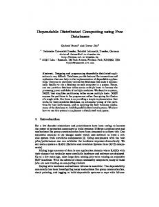
Measurement results Of the above extra-functional properties, we have decided to focus on t15b2-2, which is the assumed time of credit card validation. Using a simple simulator of the UC1 scenario, we have collected performance data related to invocations of the validateCard() method on the BankIf interface of the Bank component. The simulation was configured for 50 cash desks, started in 1 second intervals, and each processing 50 sales. The validateCard() method in the Bank component was implemented to wait a random time according to the histogram specification associated with the t15b2-2 property. The distribution of validateCard() invocation times calculated from the measured data is identical to the specified distribution, which served as a basic validation of the approach. Using the measured data, we have performed an analysis with the goal to determine the average load on the Bank component, expressed as the number of validateCard() method invocations during a 60-second interval. This load may be covered by a Service Level Agreement with a bank, which may only guarantee specific performance of its card validation service in response to a specific load.
Figure 4: The load on the card validation service of the Bank component
The results of the analysis are shown in Fig. 4, with the dashed line denoting the maximal load on the Bank component given the above simulation parameters. The rising edge of the curve starting at time 0 corresponds to the delayed startup of individual cash desks, while the falling edge starting approx at time 1100 corresponds to closing of cash desks after they have processed 50 sales. We would like to emphasize that the above analysis has been performed on data collected without actually modifying a single line of application code. Information
16
Lubomír Bulej et al.
about the distribution of durations of validateCard() invocations could be used to monitor the performance of the card validation service provided by a bank. On the other hand, runtime analysis (and throttling) of validateCard() invocation rate can be used to ensure that a store does not violate a Service Level Agreement. The overhead of the measurement was 40 microseconds per method invocation, in 99% of cases, without any attempt at performance optimization. The duration of validateCard() invocation was between 4 and 5 seconds in 90% of cases. The difference between the times is 5 orders of magnitude, which in this particular case makes the overhead of the measurement insignificant. Due space constraints, we have only included the above analysis. The Distributed System Research Group project page on CoCoME in Fractal [33] provides additional measurement results.
3.5
Specification of selected components
This section is mostly focused on behavioral view of CoCoMe components. More specifically, it assumes that the specification of component structure, interfaces, and overall architecture is taken over from the CoCoMe assignment with the few modification mentioned in Sect. 3.1. As emphasized in Sect. 3.2, the behavior specification provided here is done in behavior protocols and stems from the CoCoMe use cases and the component behavior encoded in the Java implementation provided in the CoCoMe assignment. Since the behavior specification of the whole application is too large to fit into space reserved for this chapter, two “interesting” components (CashDeskApplication and CashDeskBus) were chosen to demonstrate the capabilities of behavior protocols. Interested reader may find the specification of other “interesting” components in the appendix and full specification at [33]. Demonstrating the ordinary usage of this formalism, the behavior protocol of CashDeskApplication describes the actual behavior of a cash desk. In principle, it captures the state machine corresponding to the sale process. In contrast, the behavior protocol of CashDeskBus illustrates the specific way of expressing mutual exclusion Since both these protocols are non-trivial, their “uninteresting” fragments are omitted in this section. 3.5.1 CashDeskApplication The CashDeskApplication has application specific behavior – its frame protocol reflects the state of the current sale. It indicates what actions a cash desk allows the cashier to perform in a specific current sale state. The “interesting” parts of the protocol take the following form. ( # INITIALISED ( ?CashDeskApplicationHandler.onSaleStarted ); # SALE_STARTED ( ?CashDeskApplicationHandler.onProductBarcodeScanned{ !CashDeskConnector.getProductWithStockItem; !CashDeskApplicationDispatcher.sendProductBarcodeNotValid+ !CashDeskApplicationDispatcher.sendRunningTotalChanged
CoCoME in Fractal
17
} )*; #