Sep 13, 1996 - there can be very many ways of reducing the input tree. ... generation for idealised register machines and a restricted class of input expression trees. .... the successor nodes of only the `cheapest' node in our set at each step. ... estimated cost is obtained by using heuristic domain knowledge that is available ...
Code generation based on formal BURS theory and heuristic search A. Nymeyer, J.-P. Katoen University of Twente, Department of Computer Science, P.O. Box 217, 7500 AE Enschede, The Netherlands September 13, 1996 Abstract.
BURS theory provides a powerful mechanism to e�ciently generate pattern matches in a given expression tree. BURS, which stands for bottom-up rewrite system, is based on term rewrite systems, to which costs are added. We formalise the underlying theory, and derive an algorithm that computes all pattern matches. This algorithm terminates if the term rewrite system is nite. We couple this algorithm with the well-known search algorithm A� that carries out pattern selection. The search algorithm is directed by a cost heuristic that estimates the minimum cost of code that has yet to be generated. The advantage of using a search algorithm is that we need to compute only those costs that may be part of an optimal rewrite sequence (and not the costs of all possible rewrite sequences as in dynamic programming). A system that implements the algorithms presented in this work has been built.
Keywords: compiler generators { code generation { term rewrite systems { search algorithms { formal techniques
1 Introduction Compiler building is a time-consuming and error-prone activity. Building the front-end (i.e. scanner, parser and intermediate-code generator) is relatively straightforward|the theory is well established, and there is ample tool support. The main problem lies with the back-end, namely the code generator and optimiser|there is little theory and even less tool support. Generating a code generator from an abstract speci cation, also called automatic code generation, in an e�cient way is a very di�cult problem. Pattern matching and selection is a general class of code-generation technique that has been studied in many forms. The most successful form uses a code generator that works predominantly bottom-up; a so-called bottom-up pattern matcher (BUPM). A variation of this technique is based on term rewrite systems. This technique, popularised under the name BURS, and developed by Pelegri-Llopart and Graham [36], has arguably been considered the state of the art in automatic code generation. BURS, which stands for bottom-up rewrite system, has an underlying theory. However, to this day, BURS theory is poorly understood. Evidence of this statement are: � There has been no further development of BURS theory since its initial publication [35]. Research in so-called BURS theory has been mainly concerned with improved table-compression methods. � Researchers who claim to use BURS theory (e.g. [17, 37]) generally use `weaker' tree grammars instead of term rewrite systems. � Researchers often equate a BURS with a system that does a static cost analysis (e.g. [16]). 1
We argue that a static cost analysis is neither necessary nor su�cient to qualify as BURS, and that a system that is based on tree grammars cannot be BURS. In this work we present a lucid but concise and formal derivation of BURS theory that is based on the (semi-formal) work of Pelegri-Llopart and Graham. However, we di�er in that we do not use the instruction costs to make optimal choices statically. Instead we use a heuristic search algorithm that only needs to dynamically compute costs for those patterns that may contribute to optimal code. A result of this dynamic approach is that we do not require involved tablecompression techniques. Note that we do not address register allocation in this work; we are only interested in pattern matching and selection, and optimal code generation. We begin in the following section with a literature survey. This survey traces the development of BUPMs and BURSs, and places our research in context. In Section 3 we describe the heuristic search algorithm A� that is used to select optimal code. The algorithm A� is all-purpose|it can be used to solve all kinds of `shortest-path' problems. In our case the search graph consists of all the possible reductions of an expression tree, and we wish to nd the least expensive. In Section 4 we de ne a term rewrite system, and derive an algorithm that generates the input and output sets of an expression tree. These sets contain the patterns that match the expression tree. To select the `optimal' patterns, we use the search algorithm A� . This algorithm uses a successor function (algorithm) to select patterns and apply rewrite rules. The successor function, which is presented in Section 5, provides the search algorithm with a set of possibly-optimal selections. In this sense, the successor function couples A� and BURS. In the implementation, the algorithm that generates input and output sets, and the successor function, are modules that can be simply `plugged' into A� to produce a code generator. The implementation is also brie y described in Section 5. Finally, in Section 6, we present our conclusions.
2 Literature survey In 1977 R. Glanville submitted a thesis [20] that provided a major impetus to the eld of automatic code generation. Under the supervision of Susan Graham [21], he developed a technique that in the decade that followed was the subject of much scrutiny and re nement. Major players in this period include Henry, Ganapathi and Fischer (see [34] for a review). In the Graham-Glanville technique, as it has become known, the intermediate representation generated by the front-end of the compiler is speci ed by a context-free string grammar, and an LR-parser generator is used as a code-generator generator. Target-machine instructions are generated as a side e�ect of parsing the input expression. Unfortunately, while the technique is conceptually elegant, it proved unworkable in a production environment. The non-ambiguous LR formalism is inappropriate and too restrictive to specify the inherently ambiguous mapping from an intermediate representation to target code. As the popularity of the Graham-Glanville technique waned in the mid-1980s, interest turned to another technique, called bottom-up pattern matching.
2.1 Bottom-up pattern matchers
In this technique, we represent the input expression and target-machine instructions as trees, where the instruction trees are referred to as patterns. Corresponding to each pattern is a result (leaf or node), a target-machine instruction and a cost. If a pattern matches a subtree of the input tree, then we can replace the subtree by its result node. During code generation, we traverse the input tree bottom-up and nd all pattern matches. In a subsequent top-down traversal, we choose the least-expensive series of pattern matches that reduce the input tree into a single node. In a nal bottom-up traversal, we generate the instructions that correspond to the selected patterns. The code-generator generator in this technique reads the patterns, instructions and costs, and generates a code generator that consists of a combined pattern matcher and instruction generator. This is referred to as the static phase. In the dynamic phase, the code generator reads the input expression tree and generates target-machine instructions. What makes the problem hard is that 2
there can be very many ways of reducing the input tree. Further, the cost analysis that is necessary to determine the least-expensive reduction can be very time consuming. Early work on this technique was done by Kron [31], and by Ho�mann and O'Donnell [29]. The latter in particular have provided the basic theory for early implementations of BUPMs. Chase [10], for example, implemented a BUPM using the theory developed by Ho�mann and O'Donnell. Chase speci ed the patterns using a regular tree grammar (RTG). A RTG is a contextfree grammar with pre x notation on the right-hand sides of the productions representing trees. Chase found that the tables generated by the pattern matcher were enormous, requiring extensive use of compression techniques. Like Ho�mann and O'Donnell, Chase did not consider the problem of selecting patterns, hence he had no need for costs. A formal, concise and lucid description of Chase's table-compression technique can be found in Hemerik and Katoen [24], who formally developed naive and optimised bottom-up pattern-matching algorithms. An asymptotic improvement in both space and time to Chase's algorithm is given by Cai et al [6]. Hatcher and Christopher [23] went further than Chase and built a complete BUPM for a VAX-11. Their work was a milestone in that they carried out static cost analysis, which is a cost analysis carried out at code-generator generation time. In a dynamic cost analysis, the code generator itself performs the cost analysis. This is a space-time trade-o�. Static cost-analysis makes the code-generator generator more complex and requires a lot of space for tables. In e�ect, pattern selection is encoded into the tables. The resulting code generator, however, is simple and fast. This means that compilation is faster. We refer to a BUPM that does static (dynamic) cost analysis as a static (dynamic) BUPM. The approach of Hatcher and Christopher does not guarantee that the (statically) selected code will always be optimal. In those cases where this occurs, however, the compiler builder is warned. In both the static and dynamic BUPMs, the cost analysis is usually carried out using dynamic programming. Dynamic programming has had a long association with the eld of code generation. Early theoretical work by Aho and Johnson [2, 3] for example, considered globally optimal code generation for idealised register machines and a restricted class of input expression trees. This work used the dynamic programming algorithm [4] to generate provably optimal code. A top-down dynamic programming algorithm was used by Aho, Ganapathi and Tjiang [1] to build a codegenerator generator called twig, and by Christopher et al [11], and Weisgerber and Wilhelm [39]. The advantages of this top-down technique is that it is intuitive and that it has theoretical roots. Its disadvantage is that, because dynamic programming is done during code generation, the code generator can be slow. More recently, Fraser et al [16] have reported that twig has problems processing large grammars. In a tour de force, Henry and Damron [28, 27] compared the static and dynamic performance of the bottom-up and top-down methods, and also the Graham-Glanville and two brute-force methods, using a system called CODEGEN [25]. They found that the code generators for both the static and dynamic BUPM produce (locally) optimal code. The static BUPM had the slowest and most complex code-generator generator, but the code generator carried out pattern matching 3 times faster than its dynamic counterpart. Henry and Damron [28] remark, however, that at the time of their research, bottom-up technology was still \immature." In [26], Henry found similar di�erences in performance between static and dynamic BUPMs. In 1990, Balachandran et al [5] used a RTG and techniques based on the work of Chase, Hatcher and Christopher to build a static BUPM. Unlike the system of Hatcher and Christopher, however, no user intervention was needed to achieve optimal code. Very recently, Ferdinand et al [15] reformulated the (static) bottom-up pattern-matching algorithms (based on RTGs) in terms of nite tree automata. This theoretical work was based on the work of Kron [31]. To determine the patterns that match an input tree, they use a subset-construction algorithm. This algorithm, which is developed in a step-wise fashion, does a static cost analysis, and generalises the table-compression technique of Chase. There have been a number of notable attempts to improve the e�ciency of the dynamic (BUPM) code generator, namely Emmelmann et al [14] who developed the BEG system, Fraser et al [16] who developed the IBURG system, and very recently Gough [22] who developed the MBURG system. All used a hard-coded dynamic cost analysis. Emmelmann et al found that 3
their dynamic code generator outperformed the standard SUN-workstation (Modula-2) code generator by almost an order of magnitude, and generated code of comparable quality. Fraser et al compared their dynamic code generator with a code generator from the BURG system (described below). The BURG-system code generator does not perform a cost analysis. They found that their dynamic code generator was something like an order of magnitude slower. However, the code generator's slowness was compensated by the fact that IBURG was simpler and more intuitive in structure. In fact, it was found to be useful as a `test tool' in developing the more complex, static BURG system. Gough's MBURG system is a variant of IBURG, and more developed.
2.2 Bottom-up rewrite systems
A decade to the month after Glanville submitted his thesis, E. Pelegri-Llopart, who was also a student of Susan Graham, submitted a thesis [35] that attracted much attention. In his thesis, Pelegri-Llopart developed a code-generation system using a semi-formal approach referred to as BURS theory [36]. Pelegri-Llopart combined the static cost analysis concept from Hatcher and Christopher, the pattern-matching and table-compression techniques from Chase, and, most importantly, term rewrite systems rather than tree grammars to develop a BURS. A BURS is, in fact, a generalisation of a BUPM, and is more powerful. The term rewrite system in a BURS consists of rewrite rules that de ne transformations between terms. A term, which is represented by a tree, consists of operators and operands (which are analogous to nonterminals and terminals in context-free grammars). However, variables that can match any tree are also allowed. The advantage of using a term rewrite system is that, as well as the usual rewrite rules that reduce the expression tree, we can use rules that transform the expression tree. Algebraic properties of terms can therefore be incorporated into the code-generation process. The BURS `theory' that Pelegri-Llopart and Graham developed is quite complex, however. Pelegri-Llopart and Graham [36] compared the performance of a BURS with other techniques as part of an early (1987) implementation of Henry and Damron's CODEGEN system (see above). They found that the tables were smaller and the code generator much faster. Henry [26] also compared a BURS with a static BUPM using the CODEGEN system. He found that the static BUPM code-generator generator was 2 21 times faster but used a surprising 4 times as much space. In 1991 Emmelmann [13] used a term rewrite system to specify a mapping from intermediate to target code, and a tree grammar to specify the target terms and their costs. This idea of using di�erent formalisms to specify the target code, and the mapping from intermediate to target code originates from Giegerich [19, 18], who has carried out extensive, mainly theoretical research into this approach. Emmelmann's ambitious work pursued this approach further, and resulted in a large complex system that is unlikely ever to be completely implementable. It demonstrates that power of speci cation must be weighed up against practicality. The di�culty researchers had with BURS theory is re ected in the work of Balachandran et al, described above, who conceded that term rewrite systems are more powerful, but argued that RTGs are simpler, and more easily understood and implemented than term rewrite systems, and that better table-compression techniques could be applied. In 1992, Fraser, Henry and Proebsting [17] presented a new implementation of so-called `BURS technology'. Their system, called BURG, accepts a tree grammar (and not a term rewrite system) and generates a `BURS'. The algorithm for generating the `BURS' tables is described by Proebsting in [37]. Proebsting compares this algorithm with a table-generation algorithm from Henry [26], described above, and reports an impressive performance gain (an order of magnitude). It is not clear, however, what the relationship is between the table-generation algorithms in BURG and Pelegri-Llopart's BURS, given that they are based on di�erent formalisms.
2.3 Heuristic search techniques
The PQCC (Production-Quality Compiler Compiler) Project [40] was an early and ambitious project that aimed at automating the process of generating high-performance compilers. This work paid particular attention to the problem of phase ordering. (The phase-ordering problem 4
relates to the inter-dependence and order of the various code-generation activities like storage allocation, common-subexpression elimination, instruction selection and scheduling, (peephole) optimisation and register allocation.) Together with the Graham-Glanville and pattern-matching techniques, it was also one of the rst works that separated the target-machine description from the code-generation algorithm. The construction of the code generator and the code-generator generator in PQCC are reported by Cattell in [7, 8, 9]. There are 2 aspects of Cattell's work that are relevant to our work. � Cattell uses a means-ends analysis to determine an optimal code match. This involves selecting a set of instruction templates that are semantically close to a given pattern in the input expression tree. For each of these templates, rewrite rules (Cattell calls them axioms) are used to transform the template recursively into the pattern. The least-expensive template is chosen from those that are successful. The heuristic semantic closeness means that either the root operators match, or that there is an axiom that rewrites the root operator of the template into the root operator of the pattern. Note that the search procedure is not bounded|both the depth of the recursion and the number of semantically-close templates need to be restricted. � For performance reasons, the `major part' of the search procedure is carried out statically on a set of heuristically generated pattern trees that the code generator is likely to encounter. All the templates generated by the code-generator generator, together with the associated instruction sequences, are stored in a table for use by the code generator. The (`minor') part of the search procedure carried out by the code generator involves only 1 rule, called `fetch decomposition' by Cattell. This rule basically allocates temporary storage (or registers) to those operands that are not matched.
2.4 Summing up
Much recent research in automatic code generation has been aimed at improving the performance of the code generator by doing a static cost analysis. This research is often carried out under the name BURS, in spite of the fact that an underlying tree-grammar formalism is used. Term rewrite systems, and the `theory' developed by Pelegri-Llopart, has received scant attention in the literature. Furthermore, researchers have encountered the following problems with a static cost analysis: 1. A static cost analysis requires extensive table-compression techniques. 2. The resulting code-generator generator is complex. 3. Costs cannot depend on run-time (dynamic) parameters. 4. The cost analysis can fail (due to cost divergence, see for example [17]). However, the overriding bene t of doing a static cost analysis is that it results in a simpler and faster code generator. To the authors' knowledge, the only application of search techniques to code generation to date has been the work of Cattell in the PQCC project. Cattell's technique, however, is related to dynamic programming, and his use of heuristics is di�erent.
3 Heuristic-search methods Search techniques are used extensively in arti cial intelligence [33, 30] where data is dynamically generated. In a search technique, we represent a given state in a system by a node. The system begins in an initial state. Under some action, the state can change|this is represented by an edge. Associated with an action (or edge) is a cost. By carrying out a sequence of actions, the system will eventually reach a certain goal state. The aim of the search technique is to nd the least-cost 5
series of actions from the initial state to one of the goal states. In most problems of practical interest, the number of states in the system is very large. The representation of the system in terms of nodes, edges and costs is called the search graph. De nition 3.1 Search graphs A search graph G is de ned by a quadruple (N; E; n0 ; Ng ) with: � N , a set of nodes � E � N � N , a set of directed edges each labelled with a cost C (n; m) 2 IR, (n; m) 2 E � n0 2 N , an initial node � Ng � N , a set of goal nodes such that the following conditions are satis ed: � G is connected � Ng 6= ; � 8(n; m) 2 E : n 62 Ng
2
Note that IR denotes the set of real numbers. Traditionally, the search graph is drawn `top-down', i.e., with the initial node n0 at the top and the set of goal nodes Ng at the bottom. We adopt this convention. All edges in an acyclic search graph can therefore be assumed to point `down'. Given a search graph, the aim is to nd the least-cost path from n0 to a node in Ng . A brute-force technique that acts as a basis for nding such a least-cost path is called breadth rst search. Actually, this technique determines a shortest path from n0 to a node in Ng . In this technique, we initialise a set of nodes to fn0 g. At each step we compute the successor nodes of all the nodes in the set. The successor nodes of a given node are those nodes that can be reached with a path of length one from the node. The algorithm terminates when we nd a successor node that is a goal node. This algorithm computes all the nodes in the search graph at a certain depth, before proceeding further. At some point we will reach a depth that contains a goal node. We can use the breadth- rst search technique to determine the least-cost path by computing the successor nodes of only the `cheapest' node in our set at each step. We determine the cheapest node by determining the costs of the paths from n0 to each node in our set. The successors of the chosen node are then added to our set. This technique is called best- rst search. We can improve this technique even more if we include the estimated cost to the goal in the cost of a node. This estimated cost is obtained by using heuristic domain knowledge that is available during traversal of the search graph. By using this heuristic knowledge, we can avoid searching some unnecessary parts of the search graph. Careful choice of the heuristic can therefore reduce the number of paths that the search technique tries in an attempt to nd a goal node. The best known search technique that uses this technique is the A� algorithm. The letter `A' here stands for `additive' (an additive cost function is used), and the asterisk signi es that a heuristic is used in the algorithm. The algorithm uses the following two cost functions to direct the search: � g(n), which is the minimum cost of reaching the node n from the initial node n0 , and � h� (n), which is the estimated minimum cost of reaching a goal node from node n. Associated with each node n is a cost f �(n) = g(n) + h� (n). The actual cost of reaching a goal node from n is called h(n). The relationship between h� (n) and h(n) is important. We consider the following cases: 1. h� (n) = 0 If we do not use a heuristic, then the search will only be directed by the costs on the edges. This is called a best- rst search. 6
h� = 3 B
A
1
1 C
1
D h� = 2 1 E h� = 1 1 F
Figure 1: A search graph including the value of some heuristic at ea ch node 2. 0 < h� (n) < h(n) If we always underestimate the actual cost, then the algorithm will always nd a minimal path (if there is one). A search algorithm with this property is said to be admissible. 3. h� (n) = h(n) If the actual and estimated costs are the same, then the algorithm will always choose correctly. As we do not need to choose between nodes, no search is necessary. 4. h� (n) > h(n) If the heuristic can overestimate the actual cost to a goal node, then the A� algorithm may settle on a path that is not minimal.
Example 3.2 In this example we show what can happen when a heuristic that overestimates the actual cost is used. Consider the search graph in Figure 1. At node B the value of the heuristic is 3. This overestimates the actual cost to a goal node (C ), which is 1. At nodes D and E the values of the heuristic happen to be correct. Starting at the initial node A, if we always choose the node with the lowest value of f �(n), then, since f � (D) < f �(B ) and f � (E ) < f � (B ), we will determine that the minimum path is, incorrectly, ADEF . 2 Note, however, that in some applications (code generation, for example) it may not be important that we nd a path that is not (quite) minimal. It may be the case, for example, that a heuristic that occasionally overestimates the actual cost has superior performance than a heuristic that always plays safe. Furthermore, a heuristic that occasionally overestimates may only generate a non-minimum path in a very small number of cases. The A� algorithm is shown in Figure 2. The algorithm computes the minimum path from the initial node to a goal node. In this algorithm, we maintain two sets of nodes; open nodes No � N and closed nodes Nc � N . The algorithm begins by initialising No to fn0g, and Nc to ;. Further, the path and cost of the initial node n0 are initialised. We execute the main loop as long as we have not found a goal node. In the main loop, we use the cost function f � (n) = g(n) + h� (n) to compute Ns , which is the set of nodes in No with smallest cost. If this set contains a goal node, then we are nished, and we return the path of this node. Otherwise we choose a node out of Ns , remove it from No, add it to Nc , and compute its successors. If a successor, m say, is neither in No nor Nc , then we add m to No , and compute its path and cost. If we have visited m before, and the `new' cost of m is less than the cost on the previous visit, then we will need to `propagate' the new cost. This involves visiting all nodes on paths emanating from m and recomputing the cost (this is done by a recursive call to Propagate). The algorithm uses the functions Successor and Path. These functions are de ned below. De nition 3.3 Successor nodes
Given a search graph G = (N; E; n0 ; Ng ), we de ne the set of successor nodes Successor(n) 2 P (N ) of a node n 2 N as Successor(n) = fm 2 N j (n; m) 2 E g Note that if n 2 Ng then Successor(n) = ;. 7
2
j[ con G = (N; E; n0 ; Ng ): SearchGraph; func A star : N � j[ var No ; Nc; Ns : P (N );
n; m : N ; g; h� : N ! IR; C : N 2 ! IR; Path : N ! N � ; Successor : N ! P (N ); proc Propagate(p : N; q : N ) j[ var r : N ; if g(p) + C (p; q) � g(q) ?! skip [] g(p) + C (p; q) < g(q) ?!j[ Path(q) := Path(p) � q; g(q) := g(p) + C (p; q); for all r 2 Successor(q) \ (No [ Nc) do if Path(r) 6= Path(q) � r ?! skip [] Path(r) = Path(q) � r ?! Propagate(q; r) ]j
od
]j; Nc := ;; No := f n0 g; Path(n0 ) := n0 ; g(n0 ) := 0:0; Ns := No; do (Ns \ Ng = ;) ?! j[ choose n 2 Ns ; No := No ? f n g; Nc := Nc [ f n g; for all m 2 Successor(n) do if m 62 No [ Nc ?!j[ No := No [ f m g; Path(m) := Path(n) � m; g(m) := g(n) + C (n; m) ]j [] m 2 No [ Nc ?! Propagate(n; m)
od;
Ns := f n 2 No j 8m 2 No : g(n) + h� (n) � g(m) + h� (m) g
]j.
]j
]j od; choose n 2 (Ns \ Ng ); return Path(n)
Figure 2: The A� algorithm
8
De nition 3.4 Paths
Given a search graph G = (N; E; n0 ; Ng ), we de ne a path Path(n) 2 N � to a node n 2 N as a string of nodes in the following way: Path(n) = n0 n1 : : : nk
such that 81 � i � k : ni 2 Successor(ni?1) ^ nk = n; k � 0. 2 Note that there may be more than one path that leads to a node. Furthermore, if Path(n) = n0 n1 : : : nk and m 2 Successor(n) then we can append the node m to the path Path(n) using the append operator �. We write Path(m) = Path(n) � m = n0 n1 : : : nk m
Example 3.5 To demonstrate the A� algorithm, and the e�ect of the heuristic, we have considered the 8-puzzle. The 8-puzzle is a game consisting of a 3�3 board, and 8 tiles numbered 1 to 8. Initially the tiles are placed in some (presumably arbitrary) con guration on the board. The aim is to re-arrange the tiles until some nal con guration is reached, making as few moves as possible. The only room we have to move a tile is the vacant square on the board. The initial and goal con gurations that we use are shown below (on the left and right respectively). 1 23 8 4 7 6 5
1 6 7 2 5 4 3 8
Notice that tile 1 is already in its correct square. To reach the goal con guration, we could rst move tile 6 to the vacant square, and then move tile 2 to the square just vacated by tile 6. We would then have tile 2 in its correct position. Continuing on in this way with the other tiles we would eventually reach the goal con guration. Note that at each step, we will have to choose between at least two tiles to move to the vacant square. For simplicity, we let the cost of moving a tile be 1, so the cost of a con guration is the number of moves required to reach the con guration. Note that tiles are not moved to the (vacant) square from which they came from in the previous move. Such a move would be redundant. A node in the search graph represents a con guration, and an edge represents the action of moving a tile to the vacant square on the board. We apply the A� algorithm and the following two heuristics: 1. h0 (n) = 0. This corresponds to a best- rst search, and because the costs of all edges are all equal to 1, it also corresponds to a breadth- rst search. P 2. h1 (n) = 8i=1 j pix ? gxi j + j piy ? gyi j, where pix is the x-coordinate of tile i in the present con guration (similarly piy ), and gxi is the x-coordinate of tile i in the goal con guration (similarly gyi ). This heuristic, called the Manhattan distance, computes the number of moves that each of the eight tiles needs to make to reach its goal square, assuming no other tiles stand in the way. It usually underestimates the actual number of moves that will be required. Part of the resulting breadth- rst (i.e. corresponding to heuristic h0 (n)) search graph for the 8-puzzle is depicted in Figure 3. The initial con guration is shown as the root, and we show all con gurations up to three moves. We can read in this gure the number of nodes at depths 1, 2 and 3, namely 2, 4 and 8 (resp.). Ultimately, 22 moves are needed before the goal con guration is found (the goal is con guration number 8271 at depth 22). The total number of nodes at each depth (� 22) is shown in Table 1 (column h0 ). In total, the breadth- rst search generated 103309 (open) nodes. The performance with the heuristic h1 (n) was a very di�erent story. If we compare the two columns in Table 1 we see that at rst there is little di�erence between the number of nodes at 9
16 725 438
165 72 438
165 728 43
165 728 4 3
1 6 725 438
165 7 2 438
1 5 762 438
165 165 72 732 4 8 438
126 735 4 8
126 7 5 438
16 725 438
126 126 75 75 438 438
716 25 438
Figure 3: Part of the search graph for the 8-puzzle
depth 1 2 3 4 5 6 7 8 9 10 11
h0 2 4 8 16 20 39 62 116 152 286 396
table continued depth h 0 h1 12 748 39 13 1024 29 14 1893 26 15 2512 23 16 4485 18 17 5638 11 18 9529 4 19 10878 1 20 16993 1 21 17110 1 22 8271 1
h1 2 3 7 13 12 19 25 40 34 44 41
Table 1: The number of closed nodes in the search graph for the 2 heuristics in the 8-puzzle
10
each depth. By depth 6, however, the ratio is approximately 2 to 1. From depth 10, the heuristic begins to home in on the goal node. This is most dramatic at depth 19, at which time it `knows' the path to the goal. In total, this heuristic generated 655 (open) nodes. Both h0 and h1 generated the same path, by the way. Other heuristics were also tried. The coarser (i.e. less accurate) a heuristic is, the more nodes that are generated, and the longer it takes to nd the goal. Even a very coarse heuristic, however, is an improvement on the breadth- rst search in this application. Heuristics that occasionally overestimate the actual cost were also tried. These also performed well, and interestingly, these generated di�erent paths (but with the same cost, 22) from h0 , h1 and other heuristics that underestimated the cost. 2 Code generation considered as template or pattern matching also lends itself to the A� technique. The transformations in code generation are speci ed by rewrite rules. Each rule consists of a match pattern, result pattern, cost and an associated machine instruction. A node n is an expression tree. The initial node consists of a given expression tree. From a given node, we can compute successor nodes by transforming sub-trees that are matched by match patterns. If a match occurs, we rewrite the matched sub-tree by the corresponding result pattern. The aim is to rewrite the expression tree (node) into a goal using the least-expensive sequence of rules. The associated sequence of machine instructions forms the code that corresponds to the expression tree. In the following example we illustrate this process. Example 3.6 Consider the following set of rewrite rules, with corresponding costs and machine instructions. rule cost machine instruction (r1 ) c ?! r 1 load #c, r (r2 ) m(ri ) ?! rj 4 load (ri), rj (r3 ) m(+(c; ri )) ?! rj 7 load #c(ri), rj (r4 ) ri ?! m(rj ) 4 store ri , (rj ) (r5 ) + (ri ; rj ) ?! rj 2 add ri , rj (r6 ) + (c; r) ?! r 3 add #c, r (r7 ) + (c; m(r)) ?! m(r) 9 add #c, (r) (r8 ) + (x; y) ?! +(y; x) 0 The machine instructions consist of 3 load instructions, a store instruction and 3 add instructions. The addressing modes are register, immediate, register deferred and index. The letter c stands for constant, m for memory access, and r for register. The memory access takes one argument, and addition takes two arguments. The last rule, which expresses commutativity, contains the variables x and y. A variable may be substituted by any pattern representing an expression tree. Note that the match and result patterns are written in pre x notation, and that we di�erentiate between di�erent instances of the same symbol in a rule by using the subscripts i and j . (We only do this in this example|in the rest of this paper we omit the subscripts.) Let the initial expression tree be +(m(+(c1 ; c2 )); +(m(r1 ); c3 )), and the goal be r. We can rewrite this tree using the above rulesr in the following way: +(m(+(c1 ; c2 )); +(m(r1 ); c3 )) ==1) +(m(+(c1 ; r2 )); +(m(r1 ); c3 )) r3 == ) +(r3 ; +(m(r1 ); c3 )) r2 ==) +(r3 ; +(r4 ; c3 )) r8 == ) +(r3 ; +(c3 ; r4 )) r6 ==) +(r3 ; r4 ) r5 == ) r4 The cost of this rewrite sequence is 17. We could also have rewritten the tree in (very) many other ways. We now apply the A� algorithm. The heuristic that we use is the following:
h� (n) = 4 � jmj + 2 � j+j + jcj 11
No A0+17 B1+16 C1+16 B1+16 D5+20 E4+13 F8+9 B1+16 D5+20 E4+13 G8+9 H12+5 B1+16 D5+20 E4+13 G8+9 I13+4 J12+5 B1+16 D5+20 E4+13 G8+9 I13+4 K15+2 B1+16 D5+20 E4+13 G8+9 I13+4 L17+0
step 1 2 3 4 5 6 7
Nc choose � A A C AC F ACF H ACFH J ACFHJ K ACFHJK
Table 2: The steps that the A� procedure takes to reduce +(m(+(c1 ; c2 )); +(m(r1 ); c3 )). The subscripts are the costs g + h� at the nodes. A r1
B
+m+cc+mrc
+m+rc+mrc D
r1
C +m+cr+mrc r4 r3 r6
+m+cmr+mrc E +mr+mrc F +r+mrc r8
G
+r+cmr
r2
H +r+rc r8 r1 I +r+rr J +r+cr r6 K +rr r5 L r
Figure 4: The nodes in the heuristic search graph for the expression tree +(m(+(c1 ; c2 )); +(m(r1 ); c3 )) where j s j denotes the number of times the symbol s appears in the expression tree at n. The heuristic is derived from the costs of the instructions. Instructions that access memory (m) are deemed to be `expensive' (contributing a factor 4); an addition (+) is also moderately expensive (a factor 2); and nally a constant (c), which uses the immediate addressing mode, also contributes (a factor 1). The steps that the A� algorithm takes to reduce the initial expression tree are shown in Table 2. The steps are also indicated in Figure 4, by shaded boxes. Each edge in the graph is labelled by the rule that was applied. To make identi cation easier, each node is labelled by a letter. In step one of the algorithm, we initialise the set No to fA0+17 g, where g(A) = 0 and h� (A) = 2 � 4 + 3 � 2 + 3 = 17, and Nc to ;. We choose the node A, add its successors B1+16 and C1+16 to the set No , and move A to Nc. In step two, the nodes in No have the same cost, so we must choose between them. We adopt the policy that, when there is more than one node with the same (minimum) cost, we choose the last computed node. In this case that is C . We add the successors of C to No, move C to Nc and again choose the last, least expensive node in No . The process continues until step seven when we encounter the goal node L. The optimal path A, C , F , H , J , K and L is returned by the algorithm. This path corresponds to the rewrite sequence shown above. The code that is emitted by this sequence is the following: 12
load #c2 ,r2 load #c1 (r2 ),r3 load (r1 ),r4 add #c3 ,r4 add r3 ,r4
2
4 BURS theory In this section we derive the theory of a BURS. We rst de ne some basic concepts, and we de ne a costed term rewrite system. For a more elaborate treatment of (term) rewrite systems we refer to [12]. Given a term rewrite system and an expression tree, we can de ne rewrite sequences and permutations of rewrite sequences. Typically, the total number of rewrite sequences for a given expression tree is enormous. In Section 4.2 and 4.3 we show how the number of rewrite sequences that need to be considered can be reduced. We do this in Section 4.2 by de ning normal-form decorations of the expression tree. In a decoration, we label each node in the tree with a (possibly empty) rewrite sequence. Such a rewrite sequence is called a local rewrite sequence. A decoration is in normal form if rewrite rules are applied as low as possible in the expression tree. Rewrite sequences that correspond to decorations that are not in normal form do not need to be considered. In Section 4.3, we de ne strong normal-form decorations. These decorations have the extra property that nodes in sub-terms that match variables must be rewritten before substitution takes place. By considering only strong normal-form decorations we attempt to contain the explosion of possible rewrite sequences that can occur due to the action of variables. Finally, in Section 4.4, we present an algorithm that determines the strong normal-form decorations of an expression tree. In this algorithm, we compute the input and output sets of each node in the given expression tree. The input set of a node lists all patterns that match the sub-term rooted at that node. The output set lists the results of matching the sub-term with each of the input patterns. We also highlight in this section the similarities and di�erences between the theory that we have developed and the work of Pelegri-Llopart and Graham [36]. We refer to their work using the abbreviation PLG.
4.1 Costed term rewrite systems
We denote the set of natural numbers by IN, the set IN nf0g by IN+ , and the set of non-negative reals by IR+ .
De nition 4.1 Ranked alphabet
A ranked alphabet � is a pair (S; r) with S a nite set and r 2 S ! IN.
2
Elements of S are called function symbols and r(a) is called the rank of symbol a.1 Function symbols with rank 0 are called constants. �n denotes the set of function symbols with rank n, that is, �n = f a 2 S j r(a) = n g. We assume V is an in nite universe of variable symbols, and V � V .
De nition 4.2 Terms
For � a ranked alphabet and V a set of variable symbols, the set of terms, T� (V ) is the smallest set satisfying the following: � V � T� (V ) ^ �0 � T� (V ) � 8 a 2 �n : t1 ; : : : ; tn 2 T� (V ) ) a(t1 ; : : : ; tn ) 2 T� (V ), for n � 1
1 The term arity is sometimes used instead of rank.
13
2 For term t, Var(t) denotes the set of variables in t. Terms t for which Var(t) = ; are called ground terms. A sub-term of a term can be indicated by a path, represented as a string of positive naturals separated by dots, from the outermost symbol of the term (the `root') to the root of the sub-term. For P a set of sequences and n a natural number, let n � P denote f n � p j p 2 P g. The position of the root is denoted by ".
De nition 4.3 Positions
The set of positions Pos 2 T� (V ) ! P (IN�+ ) of a term t is de ned as: � Pos(t) = f " g, if t 2 �0 [ V � Pos(a(t1 ; : : : ; tn )) = f "; 1 � Pos(t1 ); : : : ; n � Pos(tn ) g
2 A trailing " in a position is usually omitted; for example, 2 � 1 � " is written as 2 � 1. By de nition, Pos(t) is pre x-closed for all terms t. Position q is `higher than' p if q is a proper pre x of p. The sub-term of a term t at position p 2 Pos(t) is denoted tjp .
De nition 4.4 Costed term rewrite system
A costed term rewrite system (CTRS) is a triple ((�; V ); R; C ) with � �, a non-empty ranked alphabet � V , a nite set of variables � R, a non-empty, nite subset of T� (V ) � T� (V ) � C 2 R ! IR+ , a cost function such that, for all (t; t0 ) 2 R, the following conditions are satis ed: � t0 6= t � t 62 V � Var(t0 ) � Var(t)
2 Elements of R are called rewrite rules. An element (t; t0 ) 2 R is usually written as t ?! t0 where t is called the left-hand side, and t0 the right-hand side of the rewrite rule. Elements of R are usually uniquely identi ed as r1 ; r2 , and so on. The cost function C assigns to each rewrite rule a non-negative cost. This cost re ects the cost of the instruction associated with the rewrite rule and may take into account, for instance, the number of instruction cycles, or the number of memory accesses. When C is irrelevant it is omitted from the CTRS. A term rewrite system (TRS) is in that case a tuple ((�; V ); R). The rst constraint in De nition 4.4 says that R should be irre exive, and the second constraint that the left-hand side of a rewrite rule may not consist of a single variable. The last constraint says that no new variables may be introduced by a rewrite rule. A CTRS is called ground if all left-hand sides of rewrite rules are ground terms. The CTRS de ned in the following example is a slightly modi ed version of an example taken from PLG, and will be used as a running example throughout this section. Example 4.5 Let ((�; V ); R; C ) be a CTRS, where � = (S; r), S = f +; c; a; r; 0 g, r(+) = 2; r(c) = r(r) = r(a) = r(0) = 0, and V = f x; y g. Here c represents a constant, a represents an address register and r represents a general register. The set of rules R is de ned as follows: 14
(r1 ) + x
?! y
(r3 ) + a
y
?!
(r2 )
+
+
x
(r4 )
?!
+
?!
r
a
c
x
0
x
a
r
Figure 5: The tree representation of some term rewrite rules
R = f (r1 ) +(x; y) ?! +(y; x) (r2 ) +(x; 0) ?! x (r3 ) +(a; a) ?! r (r4 ) +(c; r) ?! a (r5 ) 0 ?! c (r6 ) c ?! a (r7 ) a ?! r (r8 ) r ?! a g An alternative representation of the rst four elements of R is given in Figure 5. The cost function C is de ned as follows: C (r1 ) = C (r2 ) = C (r5 ) = 0, C (r3 ) = C (r6 ) = 3, C (r7 ) = C (r8 ) = 1 and C (r4 ) = 5. Some example terms are +(0; +(c; c)), a, and +(x; +(0; +(c; y))). For t = +(x; +(0; +(c; y))) we have that Pos(t) = f "; 1; 2; 2 � 1; 2 � 2; 2 � 2 � 1; 2 � 2 � 2 g. Some sub-terms of t are tj" = t; tj1 = x, and tj2�2 = +(c; y). 2
De nition 4.6 Substitution Let � 2 V ! T� (V ). For t 2 T� (V ), t under substitution �, denoted t� , is de ned as: � � � t = t�,(t), ifif tt 22 V�0 � a(t1 ; : : : ; tn )� = a(t�1 ; : : : ; t�n )
2
Rewrite rules that are identical, except for variable symbols, are considered to be the same. De nition 4.7 Rewrite rule equivalence Rewrite rules r1 : t1 ?! t01 and r2 : t2 ?! t02 are equivalent if and only if there is a bijection 2 � 2 Var(t1 )! Var(t2 ) such that t�1 = t2 and t01� = t02 . In this work we consider rewrite rules modulo rewrite equivalence. For our purposes it su�ces to informally de ne the notion of a rewrite step.
De nition 4.8 Rewrite step
hr;pi Given the TRS ((�; V ); R), r : t ?! t0 2 R, t1 ; t2 2 T� (V ) and p 2 Pos(t1 ), then t1 === ) t2 0 � if and only if t2 can be obtained from t1 by replacing t1 jp by t in t1 , and using the substitution � with t� = t1jp . We can also write hr; pi t1 = t2 . 2
15
(PLG refer to a rewrite step as a rewrite application.) A rewrite rule r that is applied at the root position, i.e. hr; "i, is usually abbreviated to r. A sequence of rewrite steps, called a rewrite sequence, consists of rewrite steps that are applied one after another.
De nition 4.9 Rewrite sequence r1 ;p1 i:::hrn ;pn i 0 r1 ;p1 i r2 ;p2 i Let t =h========== ) t if and only if there exists t1 ; : : : ; tn?1 such that t =h==== ) t1 =h==== ) hrn ;pni 0 : : : tn?1 =====) t . S (t) = hr1 ; p1 i : : : hrn ; pn i is called a rewrite sequence of t. We can also write S (t) t = t0 . 2 When convenient, we denote a rewrite sequence S (t) by � . Further, we write t ==�) if and only if 9 t0 : t ==�) t0 . The empty rewrite sequence is denoted ", hence t ==") t for all terms t.
The cost of a rewrite sequence � is de ned as the sum of the costs of the rewrite rules in � . The length of � is denoted j � j and indicates the number of rewrite rules in � . A rewrite step is a rewrite sequence of length 1. For rewrite sequence � and rewrite rule r, � n r denotes sequence � with r deleted2, and r 2 � denotes that r occurs in � . A� rewrite sequence �1 is called cyclic if it contains a proper pre x �2 such that for some term �2 1 ) t0 . In the rest of this paper we assume all rewrite sequences to be acyclic. ) t0 and t == t, t == If � = hr1 ; p1 i : : : hrn ; pn i then we de ne �� = f r1 ; : : : ; rn g, that is, �� is the set of rewrite rules in � . Actually, �� is a multiset as the same rewrite rule may (and often does) occur more than once in ��. De nition 4.10 Permutations Given a term t, rewrite sequences � and � 0 are permutations of each other, denoted � � =t � 0 , � � 0 0 if and only if all elements in �� and �� have the same cardinality, and t ==) t () t == ) t0 for all terms t0 . 2 0
Example 4.11 Consider the CTRS shown in Example 4.5, and let t = +(0; +(r; c)). We can r1 ;2i 0 write t =h=== ) t , with t0 = +(0; +(c; r)). We can also write hr1 ; 2i t = t0 . The term t0 is obtained from t by replacing tj2 by +(y; x)� in t, using substitution � with �(x) = r and �(y) = c such that (x; y)� = tj2 . Two derivations starting with t0 are: r4 ;2i r7 ;2i r1 ;"i r2 ;"i 1. +(0; +(c; r)) =h=== ) +(0; a) =h=== ) +(0; r) =h=== ) +(r; 0) =h=== )r hr4 ;2i hr1 ;"i hr7 ;1i hr2 ;"i 2. +(0; +(c; r)) ====) +(0; a) ====) +(a; 0) ====) +(r; 0) ====) r These rewrite sequences are permutations of each other and both have cost 6. 2 A permutation de nes an equivalence relation on rewrite sequences. In the next section we will use this fact to reduce the number of rewrite sequences that we need to consider. Note that all permutations of a rewrite sequence have the same cost. This is a stipulation for our approach, and a property of a BURS. If we use a cost function that does not satisfy this property (for example, if the cost of an instruction includes the number of registers that are free at a given moment), then the reduction, or optimisation, that we consider in the next section will lead to legal rewrite sequences being discarded. This property is therefore a restriction on the cost function and is necessary to keep the number of rewrite sequences manageable.
4.2 Normal-form decorations
Given a CTRS ((�; V ); R; C ) and two ground terms t; t0 2 T� , we now wish to determine a rewrite sequence � such that t ==�) t0 with minimal cost. If we assume that such a rewrite sequence exists, 2 This operation is only used when r can be uniquely identi ed in � .
16
then PLG refer to this as the C-REACHABILITY problem. In practice, term rewrite systems in code generation are rather extensive and allow for many possible rewrite sequences to transform t into t0 . Fortunately, an optimisation is possible so that we do not need to consider all possible rewrite sequences. This optimisation is based on an equivalence relation on rewrite sequences. The equivalence relation is based on the observation that rewrite sequences can be transformed into permuted sequences of a certain form, called normal form. Permuted rewrite sequences yield the same result for term t (cf. De nition 4.10), and they have identical costs, hence we only need to consider rewrite sequences in normal form. Normal-form rewrite sequences consist of consecutive subsequences such that each subsequence can be applied to a sub-term of t. In De nition 4.9 we de ned the rewrite sequence S (t) of a term t. We now go a step further and label, or decorate, a term with rewrite sequences. Such a rewrite sequence is called a local rewrite sequence, and is denoted by L(tjp ), where tjp is the sub-term of t at position p at which the local rewrite sequence occurs. Of course, p may be " (denoting the root). Note that all the positions in the local rewrite sequence L(tjp ) are relative to p. A term in which each sub-term is labelled by a (possibly empty) local rewrite sequence is called a decorated term, or decoration. From now on all terms that we consider will be ground terms. De nition 4.12 Decorations A decoration D(t) is a term in which each sub-term of t at position p 2 Pos(t) is labelled with a local rewrite sequence L(tjp ). 2 We can usually decorate a given term in many ways. If we wish to di�erentiate between the rewrite sequences in di�erent decorations, then we use the notation LD (tjp ). Given a decoration D(t) of a term t, the corresponding rewrite sequence S (t) can be obtained by a post-order traversal of t. Again, di�erent decorations may lead to di�erent rewrite sequences, so we denote the rewrite sequence of a decoration D by SD (t). De nition 4.13 The rewrite sequence corresponding to a decoration The rewrite sequence SD (t) corresponding to a decoration D(t) is de ned as: � LD (tj" ), if t 2 �0 SD (t) = (1 � SD (t1 ) : : : n � SD (tn )) LD (tj" ), if t = a(t1 ; : : : ; tn )
2
Here, n � � for rewrite sequence � and (positive) natural number n denotes � where each position pi in � is pre xed with n�. Decorations are considered to be the same if and only if their corresponding rewrite sequences are permutations of each other. De nition 4.14 Decoration equivalence The decorations D(t) and D0 (t) are equivalent, denoted by D(t) � D0 (t), if and only if SD (t) and SD (t) are permutations of each other, i.e. SD (t) � 2 =t SD (t). Example 4.15 Consider our running example again, and let t = +(0; +(c; c)). Two decorations D(t) and D0 (t) of t are depicted in Figure 6, on the left and right, respectively. The corresponding rewrite sequences are as follows: SD (t) = hr6 ; 2 � 1ihr7; 2 � 1ihr1 ; 2ihr4 ; 2ihr7 ; 2ihr1 ; "ihr2 ; "i SD (t) = hr6 ; 2 � 1ihr7; 2 � 1ihr1 ; 2ihr4 ; 2ihr1 ; "ihr7 ; 1ihr2 ; "i The decorations D(t) and D0 (t) are equivalent because SD (t) � 2 =t SD (t). We can de ne an ordering relation � on equivalent decorations. The intuitive idea behind this ordering is that D(t) � D0 (t) for equivalent decorations D(t) and D0 (t) if their associated local rewrite sequences for t are identical, except for one rewrite rule r that can be moved from a higher position q in D0 (t) to a lower position p in D(t). We formally state this in the next de nition. 0
0
0
0
17
"
h
0
i
r1 r7 ; 1 r 2
+
r1 r2
r1 r4 r7
+
0
"
r6 r7 c
"
+ r1 r4
+
r6 r7 c
c
"
c
Figure 6: Equivalent decorations D(t) and D0 (t) of a term t +
r3 r5 r6
0
r4 r7 r4
+
r5
0
r3
r6 c
r6 r7 c
" c
+ + r6 c
Figure 7: Two equivalent, normal-form decorations of a term t
De nition 4.16 Precedence relation
For term t and equivalent decorations D(t) and D0 (t) the precedence relation � is de ned as D(t) � D0 (t) if and only if 9 p; q 2 Pos(t), such that q is a proper pre x of p, and the following holds: � 8 s 6= p; q : LD (tjs ) = LD (tjs ) � 9 r 2 LD (tjp ) \ LD (tjq ) : LD (tjp ) n r = LD (tjp ) ^ LD (tjq ) = LD (tjq ) n r 0
0
0
0
2
�+ is the transitive closure of �. It follows quite easily that �+ is a strict partial order (i.e. irre exive, anti-symmetric and transitive) on equivalent decorations (under �). The minimal elements under �+ constitute an interesting class of decorations. These decorations are said to be in normal form. Normal forms need not be unique as �+ does not need to have a least element. De nition 4.17 Normal-form decoration A decoration D(t) of a term t is in normal form if and only if : (9 D0 (t) : D0 (t) �+ D(t)). 2 We let NF(t) denote the set of decorations of t that are in normal form. Example 4.18 In Example 4.15 we have D(t) � D0 (t) because rewrite rule r7 associated with the root position of t in D0 (t) can be moved to a lower position of t in D(t). As all local rewrite rules in D(t) are applied to the root position of the sub-term with which they are associated, they cannot be moved to a lower position, hence D(t) is in normal form. 2 Example 4.19 The two decorations shown in Figure 7 are equivalent, and are both in normal form. This illustrates that normal forms need not be unique. 2 The following theorem allows us to consider only normal-form decorations of a term t, and not the entire universe of decorations of t.
Theorem 4.20 Normal-form existence 18
Given a rewrite sequence � and term t, we have that t ==�) ) (9 D(t) 2 NF(t) : SD (t) � =t � )
Proof : Let � be an arbitrary rewrite sequence and t some term such that t ==�). A simple
decoration D0 (t) corresponding to � can be obtained by decorating the root of t with � and all other sub-terms with the empty rewrite sequence. Suppose D0 (t) is not in normal form. We informally describe a procedure to obtain from D0 (t) an equivalent decoration which is in normal form. The decoration D0 (t) can be modi ed into D1 (t) by moving a single rewrite rule from a higher position in t to a lower position in t, so that SD0 (t) � =t SD1 (t). This procedure can be repeated, until no rewrite rules can be moved to a lower position. The procedure must terminate successfully as � is nite, at which time there cannot be a decoration D0 (t) such that D0 (t) � Dn+1 (t). The result is a chain of decorations D0 (t); D1 (t); D2 (t), etc. so that Dn+1 (t) � Dn (t), for all n � 0. By construction, the last obtained decoration is a minimal element under �+ . 2 The consequence of the existence of a normal-form decoration is that the local write sequence at each position must always begin with a rewrite step that is applied to the root of the subtree rooted at that position.
Lemma 4.21
For all D(t) 2 NF(t), and p 2 Pos(t) : LD (tjp ) 6= " ) LD (tjp ) = hr; "i � , for some r 2 R and rewrite sequence � . Proof : By contradiction. Let us assume D(t) 2 NF(t) and for some p 2 Pos(t), LD (tjp ) = hr; qi � with q = n:q0 , n 2 IN+ . Let D(t) be identical to D0 (t) with the exception that L0D (tjp ) = � and L0D (tjp:n ) = LD (tjp:n )hr; q0 i. By construction D0 (t) � D(t), contradicting that D(t) 2 NF(t). 2 The approach that has been used in this section is di�erent from that of PLG. PLG rst de ne a normal-form rewrite sequence, and then a local rewrite sequence and assignment. Their local rewrite assignment is the same as our decoration. We have reversed this order. Further, our approach is more formal and concise. In particular, the explicit use of the ordering relation � is very helpful in characterising normal-form decorations.
4.3 Strong normal-form decorations
The idea behind a strong normal form is to reduce the number of local rewrite sequences that we need to consider. In the strong normal form, we do not permit positions in sub-terms of the expression tree that have matched variables in an applied rewrite rule to be rewritten again. These positions are said to have become non-rewriteable. By avoiding rewriting these positions, we avoid generating local rewrite sequences that are simply permutations of each other. All de nitions in this section are with respect to a CTRS ((�; V ); R; C ). We begin by de ning the set of positions in a term at which a variable occurs. De nition 4.22 Variable positions The set VP of variable positions of a term t 2 T� (V ) is de ned as the set of positions at which a variable occurs. In other words, VP(t) = f p 2 Pos(t) j tjp 2 V g. 2 We say that each position in a term is either rewriteable or non-rewriteable. A rewriteable position is a position in a term at which a rewrite rule may be applied. A rewrite rule may not be applied to a non-rewriteable position. If a term is rewritten using a rewrite rule that does not contain a variable, then the rewriteability of the positions in the rewritten term does not change. If the rewrite rule does contain a variable, then the positions in the term substituted for the variable become non-rewriteable. This leads us to the following de nition. De nition 4.23 Rewriteable positions The set RPt of rewriteable positions in a term t after the application of the rewrite sequence � and rewrite step ht1 ?! t2 ; pi is de ned as: 19
t0
t00 p
p t
==�)
ht1 ?!t2 ;p) i ========
q1 q2
matched matched by variables in t1 by t1
t2
Figure 8: Computing the rewriteable positions in a term after the application of ht1 ?! t2 ; pi
� RPt (") = Pos(t) � RPt (� ht1 ?! t2 ; pi) = (RPt (� ) ? Pos(t0jp )) [ Pos(t00jp ) ? fPos(t00jp�q ) j q 2 VP(t2 )g ht1 ?!t2 ;pi 00 where t ==�) t0 ======= )t .
2
In Figure 8 we depict how rewriteable positions are computed. Assume that we have some rewrite sequence t ==�) t0 . If the left-hand side of the rule t1 ?! t2 matches a sub-term at position p in t0 , then we can rewrite t0 into t00 . We do this by replacing the matched sub-term in t0 (shown lightly shaded in the term t0 in Figure 8) by the right-hand side t2 (shown lightly shaded in the term t00 ). If t1 also contains variables, then we must substitute for these variables in t2 (the matching sub-terms are shown in black in t0 and t00 ). In the de nition above, we see that the set of rewriteable positions in t00 consists of the rewriteable positions in t0 (given by RPt (� )), minus the positions in the sub-term that has been matched by t1 (Pos(t0 jp )), plus the positions in the sub-term t2 that replaced t1 (Pos(t00 jp )), and minus the positions in the sub-terms that are substituted for the variables (if any) in t2 (fPos(t00jp�q ) j q 2 VP(t2 )g). Example 4.24 We are given a TRS with S = f �; +; c; r; 2 g, corresponding ranks f 2; 2; 0; 0; 0 g, V = f x g and R de ned as follows: R = f (r1 ) �(2; x) ?! +(x; x) (r2 ) +(c; c) ?! r (r3 ) +(r; r) ?! r g Assume that we have some term t = �(2; +(c; c)). Initially, the rewriteable positions in t are given by RPt (") = f"; 1; 2; 2�1; 2�2g. If we now apply the rewrite rule hr2 ; 2i, then we generate the term t00 = �(2; r) with rewriteable positions: RPt (hr2 ; 2i) = (RPt (") ? Pos(tj2 )) [ Pos(t00j2 ) ? ; = (f"; 1; 2; 2 � 1; 2 � 2g? f2; 2 � 1; 2 � 2g) [ f2g = f"; 1; 2g In other words, each of the positions in the term �(2; r) is rewriteable. Note that the rule r2 does not contain a variable. We now apply the rewrite rule hr1 ; "i and generate t00 = +(r; r). Note that we are allowed to do this because the position " is rewriteable, and that t0 = �(2; r). The rewriteable positions in this new term are:
20
RPt (hr2 ; 2ihr1 ; "i) = (RPt (hr2 ; 2i) ? Pos(t0j" )) [ Pos(t00j" ) ?fPos(t00jq ) j q = 1; 2g = (f"; 1; 2g ? f"; 1; 2g) [ f"; 1; 2g ? f1; 2g = f"g Because the root position in the term +(r; r) is rewriteable, we can now apply the rewrite rule hr3 ; "i and generate the goal term r. Summing up, we have reduced the term t using the following sequence: r2 ;2i r1 ;"i r3 ;"i �(2; +(c; c)) =h=== ) �(2; r) =h=== ) +(r; r) =h=== )r 2 Example 4.25 Instead of beginning with the rule hr2 ; 2i in the above example, we could have begun with the rule hr1 ; "i. This results in r1 ;"i �(2; +(c; c)) =h=== ) +(+(c; c); +(c; c)) The only rewriteable position in the new term is the root position. To reduce the term further we need to reduce the sub-terms +(c; c) at positions 1 and 2. These positions, however, are nonrewriteable, hence we cannot proceed any further. Intuitively, we say that the term +(c; c) should have been rewritten before it was substituted for a variable. (This is the strong-normal-form property.) 2 As a convenience, we now de ne a boolean function Permittedt that determines whether rules in a rewrite sequence are only applied at rewriteable positions in a term t. De nition 4.26 Permitted Given the rewrite sequence � and term t, the predicate Permittedt is true if each rewrite rule r in � is applied at a rewriteable position p, and false otherwise. Formally, � Permittedt(") = true � Permittedt(� hr; pi) = p 2 RP(� ) ^ Permittedt(� )
2
De nition 4.27 Strong-normal-form decoration
A normal-form decoration D(t) is in strong normal form if and only if Permittedt(LD (tjp )) is true, for all p 2 Pos(t). 2 We let SNF(t) denote the set of decorations of t that are in strong normal form. Example 4.28 Let ((�; V ); R) be a TRS with S = f �; a; b; c; d; e; f g, r(�) = 2 and all others with rank 0, V = f x g, and R de ned as follows: R = f (r1 ) �(a; b) ?! �(c; d) (r2 ) �(c; x) ?! �(e; x) (r3 ) d ?! f g Let t = �(a; b), and de ne a decoration D(t) by local rewrite sequences LD (t) = r1 r2 hr3 ; 2i and LD (tj1 ) = LD (tj2 ) = ". The decoration D(t) is in normal form, but not in strong normal form, because r2 makes position 2 non-rewriteable. Rule r3 may not be applied to this position. The value of Permittedt (r1 r2 hr3 ; 2i) is therefore false. Note, however, that the decoration D0 (t) with LD (t) = r1 hr3 ; 2i r2 and LD (tj1 ) = LD (tj2 ) = " is in strong normal form. 2 The following theorem means that we only need to consider strong-normal-form decorations of a term t, and not the entire universe of normal-form decorations of t. This theorem is analogous to Theorem 4.20. Theorem 4.29 Strong normal-form existence Given a rewrite sequence � and term t, we have that t ==�) ) (9 D(t) 2 SNF(t) : SD (t) � =t � ) 0
21
0
0
t0
t00
p0
t000
t1 ?!t2 ;p i =h======== )
p000
�1
==)
0
ta ?!tb ;p i =h========= ) ��� 000
ta ta
ta
tv t1
tv
tv t2
Figure 9: A sequence that is not in strong normal form
Proof : Let � be an arbitrary rewrite sequence and t some term such that t ==�). From
Theorem 4.20 it follows that there exists a normal-form decoration D(t) corresponding to � . If D(t) is not in strong normal form, then there is some p such that : Permittedt (LD (t jp )). This means that we can write ta ?!tb ;p i t1 ?!t2 ;p i 00 �1 ) ��� LD (tjp ) = � � � t0 =h======= ) t ==) t000 =h======== 000
0
where t1 (and t2 ) contain at least one variable v, and ta is a sub-term of the sub-term tv of t0 that matches v. We depict the above rewrite sequence in Figure 9. In this gure, t0 = tjp . The application of the rewrite rule ta ?! tb at position p000 in the term t000 in this gure is not permitted because the (earlier) application of the rule t1 ?! t2 at position p0 in t0 resulted in all the positions in tv , including ta , becoming non-rewriteable in t00 . In Figure 9, the terms t1 and t2 are shown lightly shaded, tv is shown heavily shaded, and ta is shown in black. Without loss of generality, we assume that the positions in ta are rewriteable before the application of ht1 ?! t2 ; p0 i (note that, by de nition, all positions are initially rewriteable), and that Permittedt (�1 ) is true. We now move the instance of the rewrite rule ta ?! tb to before the rule t1 ?! t2 . This results in the rewrite sequence shown in Figure 10. In this gure we see that the rule ta ?! tb is applied at position po in term to , before the rewrite step ht1 ?! t2 ; p0 i. If we now apply the rule t1 ?! t2 , we nd that the sub-term tv that matches variable v will contain tb (instead of ta ). Note that the rule ta ?! tb is applied at position p000 in the sequence in Figure 9, and at position po in the sequence in Figure 10. The new rewrite sequence in Figure 10 is quite obviously a permutation of the sequence in Figure 9. The above procedure moves a rewrite step that is applied to a sub-term that is non-rewriteable to before the rewrite step that made the sub-term non-rewriteable. Applying this procedure repeatedly will result in a local rewrite sequence LD (tjp ) that is permissible. Given a normal-form decoration D(t), therefore, we can now make each local rewrite sequence LD (t jp ), for all p 2 Pos(t), permissible. This results in a strong-normal-form decoration. This completes the proof. 2 Example 4.30 Consider the TRS ((�; V ); R) with S = f +; c; r; a g, r(+) = 2 and all others with rank 0, V = f x; y g, and R de ned as follows: R = f (r1 ) +(c; +(c; x)) ?! +(c; x) (r2 ) +(x; y) ?! +(y; x) (r3 ) a ?! r (r4 ) +(r; r) ?! r (r5 ) +(c; r) ?! r g 00
22
t00
t0
to
p0 t1 ?!t2 ;p i =h======== )
ta ?!tb ;po i =h======== )
po
=�=1) � ��
0
ta t1
tv
tb t2
tv
tb
Figure 10: A sequence that is in strong normal form
t0
t00
+
+
t000
+ + tv h r ; 1 i r r h r ; 2 � 1 i hr4 ;2i) + =r=5) r 1 2 1 3 )c + c ====) + c ===) c + ==== + ====== not tv permitted r c c + tv c + r r a r a r c + ta ta a r
t1
t2
ta
Figure 11: A sequence that is not in strong normal form Let t0 = +(+(c; +(c; +(a; r))); c), and consider the sequence shown in Figure 11. This sequence, which is not in strong normal form, rewrites the term t0 into the goal term r. In the rst step in this sequence, t0 is rewritten into t00 by hr1 ; 1i. In this step, the sub-term tv (indicated in the gure) in t0 is matched by the variable x in t1 , and as a result, all the corresponding positions in the term t00 , including ta , have become non-rewriteable (indicated by the circled nodes). The rewrite steps r2 r1 are then applied, resulting in the term t000 , where all positions are non-rewriteable except the root. The next rewrite step, hr3 ; 2�1i, is not permitted because position 2�1, which is the position of term ta , is non-rewriteable. The node corresponding to position 2 � 1 in t000 became non-rewriteable as a result of the rst step, hr1 ; 1i. Following the strategy outlined in the proof of Theorem 4.29, we now move the rule r3 that we were not permitted to apply above, to before this step. The resulting sequence is shown in Figure 12. In this sequence we begin by applying the rewrite step hr3 ; 1�2�2�1i. This step rewrites ta into tb . We then apply rewrite step hr1 ; 1i, which results in the positions in the sub-term tv becoming non-rewriteable. We can next apply steps r2 r1 , but we cannot apply rule r4 at position 2 because it is non-rewriteable. As before, this node has became non-rewriteable as a result of the earlier step hr1 ; 1i. Repeating the above procedure, and moving the application of rule r4 to before this step, results in the sequence shown in Figure 13. This sequence is in strong normal form. Notice that in moving the rules r3 and r4 forward, the positions at which these rules are applied change. 2 In this section we have formalised the concept of rewriteable positions and strong-normal-form decorations. Rewriteable positions are related to PLG's touched positions, which PLG only treats cursorily. PLG does not explicitly de ne a strong normal form. 23
+
+
t1
t2
+
+ c hr3 ;1�2�2�1i + c hr1 ;1i + c r2 r1 hr4 ;2i + r5 = === =======) ==) r ====) = == ) c + not ) c permitted r c + c + tv c + tv r r c + c + r r a r r r +
ta
tb
Figure 12: Another sequence that is not in strong normal form + hr3 ;1�2�2�1i + c ======= )
+ c
+ c
+ +
c a
+
c r
hr4 ;1�2�2i c ====== )+
c
+ r
hr1 ;1i
c ====) +
+ c
r
+
r
c
+ c
2 r1 r5) =r==== r
r
Figure 13: This sequence is in strong normal form
4.4 Input and output sets
As a direct generalisation of bottom-up tree pattern matching methods (see e.g. [24]), sets of patterns, called input and output sets, can be computed from the strong-normal-form decorations of t. These sets de ne the patterns that match the expression tree. We begin by de ning the inputs and outputs of a decoration. De nition 4.31 Inputs of a decoration D (t) Let D(t) 2 SNF(t) such that, for some given goal term g, t =S=== ) g. For each sub-term t0 of t, the possible inputs, denoted ID (t0 ), are de ned as follows: � ID (t) = ta,(t0 ; : : : ; t0 ) ifif tt 2= �a(0t1 ; : : : ; tn ) 1 n D (ti ) where ID (ti ) =L==== ) t0i , for 1 � i � n.
2
De nition 4.32 Outputs of a decoration D (t) Let D(t) 2 SNF(t) such that, for some given goal term g, t =S=== ) g. For each sub-term t0 D (t) of t, the possible outputs are de ned as OD (t) = t0 with ID (t) =L=== ) t0 . 2 Using the inputs and outputs, we can now de ne the input set and output set of a term t for some goal term g. The input set ISg (t) is the union of all possible inputs for all strong-normal-form decorations of t. Similarly for the output set OSg (t). More formally: D (t) ISg (t) = f ID (t) j D(t) 2 SNF(t) ^ t =S=== ) gg
24
(a)
(b) {+(a,a),+(0,r),+(c,r)} + {r}
[+(0,r)] + [r]
{0} 0 {0,c,a} {+(a,a),+(r,c),+(c,r)} + {a,r}
[0] 0 [0] [+(r,c)] + [r] [c] c [r]
[c]
c [c]
{c} c {c,a,r} {c} c {c,a,r}
Figure 14: (a) Inputs and outputs of a decoration for the term +(0; +(c; c)). (b) The input and output sets of this term. D (t) OSg (t) = f OD (t) j D(t) 2 SNF(t) ^ t =S=== ) gg
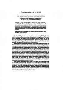
Note that the sets are de ned for a speci c goal term g. Example 4.33 Consider again our running example and the term t given by +(0; +(c; c)). A normal-form decoration D(t) for this term is shown on the left in Figure 6. The inputs ID (t) and outputs OD (t) of this decoration for goal term r are depicted in Figure 14(a). In this gure, inputs and outputs are given on the left and right side (resp.) of each node. The input sets ISr (t) and output sets OSr (t) of this term t for goal term r are shown in Figure 14(b), on the left and right side (resp.) of each node. 2 An algorithm to calculate input and output sets for terms t and g, and the corresponding local rewrite sequences is given in Figure 15. This algorithm consists of two passes. In the rst, bottom-up pass (see the function Generate) sets of triples, denoted by W (t), are computed for all possible goal terms. A triple, written ht; D; t0 i, consists of an input it, decoration D(t), and SD D (tj" ) )ot, and it =L==== )ot. For convenience, we use the type Term to denote output ot such that t == T� , SetOfTerms to denote P (Term), Triple to denote Term�Decoration�Term, and SetOfTriples to denote P (Triple). In the function Generate, the decoration D1 � : : : � Dn is obtained by decorating the root a with an empty rewrite sequence (i.e., LD (tj" ) = "), and LD (tjn�p ) = LDn (tjp ) elsewhere. Furthermore, D hr; pi is obtained by appending hr; pi to the local rewrite sequence at the root (i.e., LD (tj" )). The remaining local rewrite sequences in D are una�ected. In the second, top-down pass (the function Trim), these sets of triples are `trimmed' using the desired goal term g. The root node is trimmed by removing each triple whose output term is not identical to the goal term. Other nodes in the expression tree are trimmed by removing each triple whose output term is not identical to an input term of its parent node. The resulting trimmed sets of triples, denoted by V (t), consist of the input and output sets, and the associated decorations. Under some circumstances it may be possible to trim the nodes in the expression tree while they are being generated (see for example [38]). We do not consider that aspect further here however. Example 4.34 Let us apply the algorithm shown in Figure 15 to our running example. The set of triples V (t) for t = +(0; +(c; c)) is shown below. Note that all rewrite rules are applied at the root. V (tj1 ) = fh0; "; 0i, h0; r5 ; ci, h0; r5 r6 ; aig V (tj2�1 ) = fhc; "; ci, hc; r6 ; ai, hc; r6 r7 ; rig V (tj2�2 ) = fhc; "; ci, hc; r6 ; ai, hc; r6 r7 ; rig V (tj2 ) = fh+(a; a); r3 ; ri, h+(a; a); r3 r8 ; ai, h+(r; c); r1 r4 ; ai, h+(r; c); r1 r4 r7 ; ri, h+(c; r); r4 ; ai, h+(c; r); r4 r7 ; rig V (tj" ) = fh+(a; a); r3 ; ri, h+(0; r); r1 r2 ; ri, h+(c; r); r4 r7 ; rig 25
j[ con ((�; V ); R): TermRewriteSystem;
: Term; var W (t); V (t): SetOfTriples; func Generate (t : Term): SetOfTriples j[ var H; Z (t): SetOfTriples; i : IN; H := Z (t) := ;; if t :: a ?! Z (t) := f ht; D" ; tig; [] t :: a(t1 ; : : : ; tn ) ?! j[ for all 1 � i � n do Z (ti ) := Generate(ti ) od; (� Let O(ti ) = f otki j hitki ; Dki ; otki i 2 Z (ti ) g �) for all (tk1 ; : : : ; tkn ) 2 O(t1) � : : : � O(tn) do Z (t) := Checknf (Z (t); ha(tk1 ; : : : ; tkn ); Dk1 � : : : � Dkn ; a(tk1 ; : : : ; tkn )i) od ]j ; do H 6= Z (t) ?!j[ H := Z (t); for all hit; D; oti 2 Z (t) do for all p 2 RPt(SD ) ^ (LD (tj") = " ) p = ") do for all r 2 R ^ SD hr; pi is acyclic hr;pi do if ot === 6 ) ?! skip t; g
hr;pi 0 [] ot === ) ot ?! Z (t) := Checknf (Z (t); hit; D hr; pi; ot0 i)
od; return Z (t)
]j
od
od
od
]j;
func Checknf (Z : SetOfTriples, hit; D; oti : Triple): SetOfTriples j[ var exit: Bool; exit := false; for all hit0; D0 0 ; ot0i 2 Z 0^ : exit do if D � D0 ^ D0� D ?!j[ exit := true; Z := (Z n f hit0; D0 ; ot0 ig) [ f hit; D; oti g ]j [] D � D ^ D � D ?! exit := true [] D 6� D0 ?! skip od; if : exit ?! Z := Z [ f hit; D; otig [] exit ?! skip ; return Z ]j;
func Trim (t : Term; tg : SetOfTerms): SetOfTriples j[ var Z (t): SetOfTriples; i : IN; Z (t) := f hit; D; oti 2 W (t) j ot 2 tg g; if t :: a ?! skip [] t :: a(t1 ; : : : ; tn ) ?! for all 1 � i � n do Z (ti ) := Trim(ti ; f itji j hit; D; oti 2 Z (t) g) od ; return Z (t) ]j;
( ) := Generate(t); ( ) := Trim(t; fgg)
W t V t
]j.
Figure 15: A two-pass algorithm to calculate the input sets, decorations and output sets 26
2
To guarantee termination of this algorithm the length of each local rewrite sequence must be nite. A TRS that has this property is referred to as nite, and one that does not as in nite. More speci cally, a TRS is nite if and only if LD (tjp ) is nite for all D(t) 2 SNF(t), t 2 T� (V ) and p 2 Pos(t). Intuitively, in nite TRSs occur because the right-hand side of a rewrite rule can be more complex than the left-hand side. In that case, sequences can continue inde nitely. Example 4.35 Consider the TRS with rules: (r1 ) c ?! m(c) (r2 ) m(c) ?! a (r3 ) m(a) ?! r The TRS is in nite because we can generate the following local rewrite sequence for the input term c: r1 ;1i r1 ;1�1i hr1 ;1�1�1i r1 ) m(c) =h=== ) m(m(c)) =h==== ) m(m(m(c))) ====== ) ��� c == A successful rewrite sequence for this input term involves (only) 2 applications of rule 1, as shown below: r1 ;1i r2 ;1i r3 r1 )r 2 ) m(c) =h=== ) m(m(c)) =h=== ) m(a) == c == The maximum length of local rewrite sequences in a nite TRS may not be bounded. In that case the length will be dependent on the input term. Example 4.36 Consider the TRS with rules: (r1 ) m(+(c; X )) ?! m(X ) (r2 ) m(r) ?! r where r is the goal term. Local rewrite sequences for this TRS will be nite in length, but unbounded. For example: r2 r1 )r ) m(r) == m(+(c; r)) == r2 r1 r1 )r ) m(r) == m(+(c; +(c; r))) ==) m(+(c; r)) == 2 r2 r1 r1 r1 )r ) m(r) == m(+(c; +(c; +(c; r)))) ==) m(+(c; +(c; r))) ==) m(+(c; r)) == If the length of local rewrite sequences for a given TRS is bounded, by k say, then PLG say that the TRS satis es the BURS property. (Note that our running example satis es the BURS property with k = 3.) PLG de ne the following su�cient syntactic condition for a nite TRS:
Theorem 4.37
A TRS ((�; V ); R) is nite if for all (t; t0 ) 2 R one of the following conditions holds: 1. V ar(t) = ; and t0 2 �0 2. t = a(t1 ; : : : ; tn ) and t0 = b(t1 ; : : : ; tn ) for n � 0 and a; b 2 �n 3. t = a(t1 ; : : : ; tn ) and t0 = a(t�(1) ; : : : ; t�(n) ) with � a permutation on [1; n] 4. t = f (x; t00 ) and t0 = x with V ar(t00 ) = ; This result has been con rmed, in a somewhat di�erent context, by Kurtz [32]. It would be interesting to identify a coarser classi cation of nite TRSs. PLG de ne inputs and outputs, as we do, and use these to build local rewrite graphs for each sub-term of the given expression tree. These graphs represent the local rewrite sequences of all `normal-form rewrite sequences' that are applicable. We directly encode the inputs, outputs and local rewrite sequences into the expression tree (in the form of triples attached to each node).
27
5 Coupling A� and BURS The search graph G = (N; E; n0 ; Ng ) consists of a set of nodes N , edges E and goal nodes Ng , and an initial node n0 . A node represents a state of the system, and is denoted by a quadruple (t; p; �; t0 ) where t is the current term, p is the current position in that term, � the local rewrite sequence applied at p, and t0 the (chosen) input tree at p. The initial node n0 is given by the quadruple (tI ; p0; �; tI jp0 ). The term tI is the input expression tree for which we want to generate code. The initial position p0 is the lowest left-most position in this tree, and is of the form 1 � 1 � : : : Example 5.1 Consider our running example (Example 4.5). The initial node is the quadruple (+(0; +(c; c)); 1; �; 0). The lowest left-most position in tI = +(0; +(c; c)) is 1, and tI j1 is 0. The set of goal terms is the singleton set frg. 2 To determine the search graph, we need to compute the successor nodes of a given node. This is carried out by the function Successor, which is shown in Figure 16. As in Figure 15, we use the type SetOfTriples. We also denote the type (R � IN�+ )� by RewriteSequence, and P (T� � IN�+ � (R � IN�+ )� � T� ) by SetOfQuadruples. The (standard) functions Next, Parent and Child are used to position ourselves in the search graph. These functions are de ned below.
De nition 5.2 Next, Parent and Child Given a position p 2 Pos(t) n f�g in a term t: � Next(p; t) 2 IN�+ is the next position of p in a post-order traversal of t. � Parent(p; t) 2 IN�+ is the position of the parent of p in t. � Child(p; t) 2 IN+ is the child-number of p in t. 2 If a position p in tree t has children p � 1; : : : ; p � n then the child-number of position p � i is i. Further, Parent(�,t) = Child(�,t) = �, but Next(�,t) is unde ned, for any t. Note that p = Parent(p,t)�Child(p,t). Example 5.3 In the term t = +(0; +(c; c)), we have Next(1,t) = 2�1, Next(2�1,t) = 2�2, Next(2�2,t) = 2 and Next(2,t) = �. Furthermore, Parent(2�1,t) = 2 and Child(2�1,t) = 1. 2
The basic idea behind the successor function is the following. If we can add a rewrite step (hr; p0 i in the algorithm) to a local rewrite sequence (� ) at the current position (p), and there exists a rewrite sequence (� hr; p0 i� 0 ) whose output tree (ot) matches a corresponding child of an input tree (it 0 ) of the parent (of p), and all the younger siblings of the current position also match corresponding children of the same input tree, then we have found a successor node. If position p is the i-th child (of a node) then the younger siblings are the children 1 until i ? 1. The rst child has no younger siblings of course. The function Successor is called recursively, using the next post-order position, for as long as the sub-term at the current position, and all the younger siblings of the current position, match corresponding children of an input tree of the parent. The function Match carries out the task of matching a node (sub-tree) and its siblings with the children of an input tree of the parent. When the algorithm reaches the root position, p = �, the recursion will stop, and the function Match will always yield true. The algorithm will return with the empty set when it reaches the root position and the term t 2 Ng . Example 5.4 Consider our running example again. Let us compute the successor nodes of the initial node, i.e. we compute Successor(+(0; +(c; c)); 1; �; 0). Because p 6= � and Match(1; t j1 ) = true, we recursively call the function again with the next position, p = 2 � 1. That is, we call Successor(+(0; +(c; c)); 2 � 1; �; c) where the last argument c = t j2 � 1. Again, p 6= � and Match(2 � 1; t j2 � 1 ) = true, so we recursively call Successor, this time with p = 2 � 2. That is, we call Successor(+(0; +(c; c)); 2 � 2; �; c) where the last argument c = tj2 � 2. The recursion now stops 28
j[ con ((�; V ); R): TermRewriteSystem;
V (t): SetOfTriples; func Successor (t : T�; p : IN�+; � : RewriteSequence; it : T�): SetOfQuadruples j[ var S : SetOfQuadruples; func Match(p0 : IN�+; t0 : T�): Bool j[ var Z : SetOfTerms ; it 0 : Term ; b: Bool ; b := (p0 = �); Z (t) := f it j hit; D; oti 2 V (tjParent(p ) ) ^ itjChild(p ) = t0 g; (� if p0 is the i-th child, then Z is the set of input trees of its parent such that the i-th child of each term in Z equals t0 �) do Z 6= ; ^ :b ?!j[ choose it 0 2 Z ; Z := Z n fit 0 g; b := (8 1 � i < Child(p0 ) : it 0ji = tjParent(p ) � i ) ]j od; return b ]j; (� body of function Successor �) if (p = �) _ :Match(p; tjp ) ?! S := ; [] (p 6= �) ^ Match(p; tjp ) ?! S := Successor(t; Next(p); �; tjNext(p) ) ; for all r 2 R do for all p0 2 Pos(it) do for all hit; D; ot i 2 V (tjp ) ^ SD = � hr; p0 i� 0 (� loop over � 0 and ot �) do if :Match(p; ot) ?! skip [] Match(p; ot) ?! S := S [ f (hr; p0 it; p; � hr; p0 i; it) g 0
0
0
od
]j.
]j
od od; return S
Figure 16: The successor function that computes a set of new search nodes
29
A +0+cc
1r5 B +c+cc
2�1r6
1r6 E +a+cc
2�2r6
2�1r6
2�2r6
2�1r7
C +0+ac
2�2r6
F +c+ac
2�2r6
2�1r6
2�1r7
2�2r6
D +0+ca
2�2r7
2r1
2�1r7
2�2r6
2�2r7
2r1
2r3
+a+cr +ar
2r4 +aa
r3
�
r
2r8 +aa
r3
�
r
2r4 +aa
r3
�
r
2r1
2r3
+ca
+c+cr +cr
2r4
+ca
2r7 +cr
r4
a
+0a
2r7 2r7
r4
�
+cr
r4
r7
�
�
a
r
r7
�
�
a
r
+0r
r1
+r0
r1
r2
r2
�
a
r7
r2
�
r1
�
S +r0 +0r
+a0 T r
�
r
�
�
�
R +0a
r1 2r7
2r4
2r4
2r4
2r3
K +a+ac L +a+ca M +c+rc N +c+aa O +c+cr P +0+cr Q +0r
+a+rc +a+aa +a+cr
2�2r7
G +c+ca H +0+rc I +0+aa J +0+cr
+a0
r1
r2
�
+r0
r2
�
a
�
r
r7
�
r
�
r
r7
�
r
Figure 17: For the expression tree +(0; +(c; c)), the (a) complete search graph, (b) best- rst search graph (in boxes), and (c) heuristic search graph (in shaded boxes) because Match(2 � 2; tj2 � 2) = false (there is no input tree it0 of tj2 in which it0 j1 = c ^ it0 j2 = c). We therefore let S := ;, and inspect all the triples of V (tj2 � 2 ). The triples at each position in t were computed in Example 4.34. The triple hc; r6 r7 ; ri satis es the loop condition, with it = c, � = �, r = r6 , � 0 = r7 and ot = r. We also nd Match(2 � 2; r) = true (for it0 = +(c; r)), hence we generate the search node (+(0; +(c; a)); 2 � 2; r6 ; c). The call of Successor for p = 2 � 2 is now complete, so we need to inspect the triples associated with the previous position, V (tj2 � 1 ). The triple hc; r6 r7 ; ri (again) satis es the loop condition, Match(2 � 1; r) = true (this time for it0 = +(r; c)), and we generate the search node (+(0; +(a; c)); 2 � 1; r6 ; c) The call of Successor for p = 2 � 1 is also now complete. Inspecting the triples associated with the initial position, V (t j1 ), we nd that triple h0; r5 r6 ; ai satis es the loop condition, and that Match(1; a) = true (for it0 = +(a; a)). We therefore generate the search node (+(c; +(c; c)); 1; r5 ; 0). The result of the above computation is that we have generated the following set of search nodes: f(+(0; +(c; a)), 2 � 2, r6 , c), (+(0; +(a; c)), 2 � 1, r6 , c), (+(c; +(c; c)), 1, r5 , 0)g In Figure 17 we see the complete search graph for the expression tree +(0; +(c; c)). Note that instead of the lengthy quadruple notation, we have used the rst argument of the quadruple (the term) as node name, and we have labelled the edges with the rule number concatenated with the position at which the rule must be applied. For the sake of convenience, we have also named some of the nodes. For example, if we are at node A, which is the term +(0; +(c; c)), and apply the rule r5 at position 1, then we generate node B , which is +(c; +(c; c)). We can construct more nodes in the search graph by computing the successors of B , C and D. We will consider just the node B here, and compute Successor(+(c; +(c; c)), 1, r5 , 0). Because p 6= � and Match(1; tj1 ) = true, we must rst recursively call Successor(+(c; +(c; c)), 2 � 1, �, c). Again, p 6= � and Match(2 � 1; tj2 � 1 ) = true, so we call Successor(+(c; +(c; c)), 2 � 2, �, c). The triple hc; r6 ; ai 2 V (t j2 � 2 ) hence this last call generates the node (+(c; +(c; a)), 2 � 2, r6 , a). The same triple results in the previous call generating the node (+(c; +(a; c)), 2 � 1, r6 , a). This leaves us with only the initial call of Successor. For it = 0, � = r5 , r = r6 , � 0 = � and ot = a we nd that 30
step 1 2 3 4 5 6 7 8 9 10
No A0 B0 C3 D3 C3 D3 E3 F3 G3 C3 D3 E3 F3 O4 C3 D3 E3 O4 M4N6 C3 D3 O4 M4 N6 K6 L6 C3 O4 M4 N6 K6 L6J4 O4 M4 N6 K6 L6 J4 H4 I6 O4 M4 N6 K6 L6 J4 I6 P4 :::
Nc choose � A A B AB G ABG F ABGF E ABGFE D ABGFED C ABGFEDC H ABGFEDCH :::
Table 3: The initial steps that the A� procedure takes to reduce +(0; +(c; c)) using a best- rst search strategy (the subscripts are the costs g) the triple h0; r5 r6 ; ai 2 V (tj1 ), and hence generate the node (+(a; +(c; c)), 2 � 1, r5 r6 , 0). Note that � 6= � here|this is the rst time that we have built-on a rewrite sequence. The end result is that the set of successor nodes of (+(c; +(c; c)), 1, r5 , 0) is: f(+(c; +(c; a)), 2 � 2, r6 , c), (+(c; +(a; c)), 2 � 1, r6 , c), (+(a; +(c; c)), 1, r5 r6 , 0)g These nodes correspond to the nodes G, F and E in Figure 17, respectively. We arrive at a goal node when a node consists of a goal term. A goal node has no successor nodes. Note that there are a total of 11 paths leading from the initial node to a goal node in Figure 17. 2 In the example above, we have shown how the successor function shown in Figure 16 can be used to compute the complete search graph for a given rewrite system and expression tree. Calling the successor function for each and every newly created node can result in a very large tree, and is wasteful as we only wish to nd one least-cost path. We could instead call the successor function from the A� search algorithm, shown in Figure 2. The A� algorithm will compute successors for only those nodes that potentially lie on a least-cost path from the initial node n0 to some goal node. The cost g(n) of a path from n0 to some node is simply the sum of the costs of the rewrite rules applied along the path. For the moment we let the heuristic cost function h� (n) = 0, hence the cost that A� uses, f � (n) = g(n). This corresponds to a best- rst search. Example 5.5 We now apply the best- rst search algorithm to our running example. We begin by initialising the sets Nc to ; and No to the initial node fAg. The successors of A are B0 , C3 and D3 , where the subscripts are the values of the costs of the nodes. Hence, in step 2, No = fB0 ; C3 ; D3g and we move A to Nc . The node B is the least expensive, so we compute its successors, which are nodes E3 , F3 and G3 , add them to No, and move B to Nc . The rst 9 steps in this process are shown in Table 3. Note that we always choose the last computed least-expensive node. The resulting best- rst search graph is shown in Figure 17. The rewrite sequence associated with the optimal path to T is h2 � 1; r6 ih2 � 2; r6 ih2; r3 ih�; r1 ih�; r2 i. This sequence rewrites the expression tree +(0; +(c; c)) into r for a total cost of 9. 2 In the example above, we still had to compute a large part of the search tree to determine a least-cost path. We can do better by using the A� algorithm with a non-zero cost heuristic h� (n). In principle, of course, we cannot predict how much it will cost to rewrite a given node to a goal node. However, we can provide an (under) estimate of the cost. In particular we are interested in predicting when `expensive' rewrite rules will be necessary to rewrite a term. Example 5.6 Let us deduce a heuristic function that will `predict' the cost for our running example. For convenience, the rewrite rules are shown again below. The column on the right are the costs.
31
step 1 2 3 4 5 6 7
No A0+9 B0+15 C3+6 D3+6 B0+15 C3+6 J4+6 B0+15 J4+6 H4+6 I6+3 B0+15 J4+6 H4+6 Q9+0 B0+15 J4+6 H4+6 S9+0 B0+15 J4+6 H4+6 T9+0
Nc choose � A A D AD C ADC I ADCI Q ADCIQ S ADCIQS goal
Table 4: The steps that the A� procedure takes to reduce +(0; +(c; c)) using a heuristic search (the subscripts are the costs g + h� ) (r1 ) + (x; y) ?! +(y; x) 0 (r2 ) + (x; 0) ?! x 0 (r3 ) + (a; a) ?! r 3 (r4 ) + (c; r) ?! a 5 (r5 ) 0 ?! c 0 (r6 ) c ?! a 3 (r7 ) a ?! r 1 (r8 ) r ?! a 1 The heuristic cost is a function of the term t in a node n. The rst observation that we make is that a +-node that does not have a 0-node as child will cost at least 3 to rewrite to our goal r. The second observation is that a node c will also cost at least 3 to rewrite. Note the special case +(c; r) satis es both conditions and costs 5+1 to rewrite to r. Combining these observations, we produce the following heuristic:
h� (n) = 3 � (j+0j + jcj) where n = (t; p; �; t0 ), j+0j denotes the number of nodes labelled + and with no children labelled 0, and jcj denotes the number of nodes labelled c. This heuristic cost under-estimates, or is equal to, the actual cost. For example, h� = 0 for t = a (actual cost is 1), h� = 3 for t = +(0; c) (actual cost 4) and h� = 6 for t = +(c; a) (actual cost 6). We now apply the A� search algorithm with this heuristic to our running example. The steps that the algorithm takes are shown in Table 4. The nodes in No this time have subscripts g + h� . The goal node T , with a (minimum) cost of g = 9, is found in 7 steps. The resulting heuristic search graph is shown in Figure 17. In total, only 10 nodes needed to be visited before the optimal path was discovered. 2 Implementation. The A�, pattern-matching and successor-function algorithms have been implemented in C. The A� algorithm is almost completely application-independent. An application can be the 8-puzzle, or the BURS pattern matcher, for example. The A� algorithm calls a) a routine to initialise the application, b) the successor function to determine new nodes, and c) a simple cost function that returns with the cost of an `edge' (i.e. rewrite rule). These 3 routines comprise the interface between A� and the application. The A� algorithm (i.e. Algorithm 2) required approximately 500 lines of code. Implementing BURS (Algorithm 15) and the successor function (Algorithm 16) was an involved task. It required approximately 2500 lines of code, and consists of mainly intricate treemanipulation routines. TRSs for real machines have not, as yet, been developed, hence meaningful performance gures cannot be given. However, the implementation has revealed the strength and validity of the theory. Consider, for example, the role that the strong normal form plays in reducing the number of rewrite sequences that need to be generated in the BURS. In a rewrite sequence that is in strong normal form, rewrite steps are not applied at positions that result from the substitution of a variable. Without this restriction, the number of (local) rewrite sequences 32
+ r a +
+
+ ==) r1
a
+ a
a r
+ r
+ ==)
+ a
r
+ r1
a
r
a
3 + ====) a a a
r
r7 ;1i =h=== )
+ r
a ==) r1
r ==) r
+
hr8 ;2�2i
+ =====) r r
+
r
+ r
a ==) r1
r
r8 ;1i =h=== )
a
a
+ a
=r=3)
hr ;2�1i
7 + =====)
r
hr ;2i
1 + ====)
a
hr ;2�1i
8 + =====)
a
a
r
+ r
+
hr8 ;2i
r ====) +
r8 ;2i =h=== )
a a
r
a
+
r
r1
+ r
+
a
r
hr1 ;1i
r
a =====)+
+
r ====) +
+
hr ;2i
a ====) +
+
hr7 ;1�2i
a
hr7 ;2i
r
+ r
a
+
+ ==) r
r ====) +
a
r1
+
hr8 ;2i
a
r =r=8) a
Figure 18: A rewrite sequence of length 21 can grow exponentially. This growth is caused by the rewrite rules that contain variables. Example 5.7 Consider the term +(r; +(a; a)), and the rewrite rules from our running example. The number of local rewrite sequences in strong normal form that can be applied rat the root of this term is 1, and the length of this sequence is also 1. The sequence is +(r; +(a; a)) ==1) +(+(a; a); r). We cannot apply any more rewrite steps to the output term here because the sub-terms +(a; a) and r have become non-rewriteable. Now consider the local rewrite sequences that are not in strong normal form (SNF). With no restriction on where we apply rewrite steps, we can generate many rewrite sequences. For example, we could apply hr7 ; 1�1i, or hr7 ; 1�2i, or hr8 ; 2i to the output term above. If we continue this process, we will quickly nd that a combinatorial explosion ensues. In fact, the total number of non-SNF local rewrite sequences turns out to be 335,481! The lengths of these rewrite sequences range between 1 and 21. In Figure 18 we show an example of one of the longest sequences. Notice that the rewrite rule r1 is applied a total of 8 times in this sequence. 2 Note that the sequences that we referred to in the previous example have not been trimmed. In other words, and to be more speci c, these are the sequences � in W (t) that are generated by the routine Generate() in Algorithm 15, where the non-SNF sequences have been generated by not enforcing the restriction p 2 RPt (� ). We chose the term +(r; +(a; a)) in the previous example because the number of non-SNF rewrite sequences for our `running' term +(0; +(c; c)) is too large to be easily computed. In the table below we show the number of sequences, both strong and non-strong, for each node in the term +(0; +(c; c)). For completeness, we also show the number of sequences after trimming (c.f. Example 4.34).
33
position
tj1 tj2�1 tj2�2 tj2 tj"
non-trimmed trimmed SNF non-SNF 4 4 3 3 3 3 3 3 3 21 215 6 101 � 106 3
6 Conclusions In this work we have derived BURS theory, and used this theory to construct an algorithm that determines all the pattern matches (in the form of input and output sets) of a given expression tree. BURS theory is based on term rewrite systems, which provide a more powerful formalism in the eld of code generation than the more popular regular tree grammars. Given the input and output sets, the A� search algorithm is used to select patterns. Instead of computing the cost of all possible matches, the A� algorithm uses a heuristic best- rst technique that applies only those rewrite rules that may form part of an optimal rewrite sequence. The cost criterion that is used is based on the costs of the rewrite rules and a heuristic that estimates the cost of rewriting a term into a goal term. The main contributions of this work are threefold: � We have provided a theoretical framework for BURS and presented an algorithm for pattern matching based on this framework. � We have coupled this pattern-matching algorithm with a search algorithm to produce a code generator that generates optimal code. � We have introduced the novel concept of a heuristic that predicts the minimum (future) cost of rewriting a term into a goal term. The algorithms presented in this work have all been implemented. This has demonstrated the correctness of the approach, and allowed experimentation with the heuristic cost function. Note that, like the term rewrite system itself, the cost heuristic is determined by the compiler writer. We should emphasise that only when the heuristic cost under-estimates the actual cost is optimality guaranteed. In that case the search algorithm is said to be admissible (see Section 3). There are a number of directions for future research: � Develop term rewrite systems for real machines, and test the performance of the prototype. � Develop a systematic technique of constructing a heuristic cost function. Further, determine the su�cient and necessary conditions under which a given heuristic will not over-estimate the real cost. � Investigate whether code optimisation and register allocation can be expressed in terms of a term rewrite system. � Investigate whether certain parts of the pattern-matching algorithm can be done statically. � Consider how to determine a priori whether a term rewrite system is nite.
Acknowledgement: Ymte Westra and Henk Alblas were involved in the initial phase of this work. Many thanks to the referees for their helpful suggestions.
34
References [1] A. V. Aho, M. Ganapathi, and S. W. K. Tjiang. Code generation using tree matching and dynamic programming. ACM Transactions on Programming Languages and Systems, 11(4):491{516, October 1989. [2] A. V. Aho and S. C. Johnson. Optimal code generation for expression trees. Journal of the ACM, 23(3):488{501, 1976. [3] A. V. Aho, S. C. Johnson, and J.D. Ullman. Code generation for machines with multiregister operations. In Conference Record of the Fourth Annual ACM Symposium on Principles of Programming Languages, pages 21{28, 1977. [4] A. V. Aho, R. Sethi, and J. D. Ullman. Compilers: Principles, Techniques and Tools. AddisonWesley, Reading, MA, 1986. [5] A. Balachandran, D. M. Dhamdhere, and S. Biswas. E�cient retargetable code generation using bottom-up tree pattern matching. Computer Languages, 15(3):127{140, 1990. [6] J. Cai, R. Paige, and R. Tarjan. More e�cient bottom-up multi-pattern matching in trees. Theoretical Computer Science, 106:21{60, 1992. [7] R. G. G. Cattell. Code generation in a machine-independent compiler. Proceedings of the ACM SIGPLAN 1979 Symposium on Compiler Construction, ACM SIGPLAN Notices, 14(8):65{ 75, August 1979. [8] R. G. G. Cattell. Automatic derivation of code generators from machine descriptions. ACM Transactions on Programming Languages and Systems, 2(2):173{190, April 1980. [9] R. G. G. Cattell. Formalization and Automatic Derivation of Code Generators. UMI Research Press, Ann Arbor, Michigan, 1982. [10] D. R. Chase. An improvement to bottom-up tree pattern matching. In Proceedings of the Fourteenth Annual ACM Symposium on Principles of Programming Languages, pages 168{ 177, Munich, Germany, January 1987. [11] T. W. Christopher, P. J. Hatcher, and R. C. Kukuk. Using dynamic programming to generate optimised code in a Graham-Glanville style code generator. Proceedings of the ACM SIGPLAN 1984 Symposium on Compiler Construction, ACM SIGPLAN Notices, 19(6):25{36, June 1984. [12] N. Dershowitz and J.-P. Jouannaud. Rewrite systems. In J. van Leeuwen, editor, Handbook of Theoretical Computer Science (Vol. B: Formal Models and Semantics), chapter 6, pages 245{320. Elsevier Science Publishers B.V., 1990. [13] H. Emmelmann. Code selection by regularly controlled term rewriting. In R. Giegerich and S. L. Graham, editors, Code generation|concepts, tools, techniques, Workshops in Computing Series, pages 3{29. Springer-Verlag, New York{Heidelberg{Berlin, 1991. [14] H. Emmelmann, F. W. Schroer, and R. Landwehr. BEG|a generator for e�cient back ends. ACM SIGPLAN Notices, 24(7):246{257, July 1989. [15] C. Ferdinand, H. Seidl, and R. Wilhelm. Tree automata for code selection. Acta Informatica, 31(8):741{760, 1994. [16] C. W. Fraser, D. R. Hanson, and T. A. Proebsting. Engineering a simple, e�cient codegenerator generator. ACM Letters on Programming Languages and Systems, 1(3):213{226, September 1992. 35
[17] C. W. Fraser, R. R. Henry, and T. A. Proebsting. BURG|fast optimal instruction selection and tree parsing. ACM SIGPLAN Notices, 27(4):68{76, July 1992. [18] R. Giegerich. Code selection by inversion of order-sorted derivors. Theoretical Computer Science, 73:177{211, 1990. [19] R. Giegerich and K. Schmal. Code selection techniques: pattern matching, tree parsing, and inversion of derivors. In H. Ganzinger, editor, Proc. 2nd European Symp. on Programming, volume 300 of Lecture Notes in Computer Science, pages 247{268. Springer-Verlag, New York{Heidelberg{Berlin, 1988. [20] R. S. Glanville. A Machine Independent Algorithm for Code Generation and its Use in Retargetable Compilers. PhD thesis, University of California, Berkeley, December 1977. [21] R. S. Glanville and S. L. Graham. A new method for compiler code generation. In Conference Record of the Fifth Annual ACM Symposium on Principles of Programming Languages, pages 231{240, Tucson, Arizona, January 1978. [22] K. J. Gough. Bottom-up tree rewriting tool MBURG. ACM SIGPLAN Notices, 31(1):28{31, January 1996. [23] P. J. Hatcher and T. W. Christopher. High-quality code generation via bottom-up tree pattern matching. In Proceedings of the Thirteenth Annual ACM Symposium on Principles of Programming Languages, pages 119{130, Tampa Bay, Florida, January 1986. [24] C. Hemerik and J.-P. Katoen. Bottom-up tree acceptors. Science of Computer Programming, 13:51{72, January 1990. [25] R. R. Henry. The codegen user's manual. Technical report 87-08-04, Computer Science Department, University of Washington, Seattle, Washington, October 1988. [26] R. R. Henry. Encoding optimal pattern selection in a table-driven bottom-up tree-pattern matcher. Technical report 89-02-04, Computer Science Department, University of Washington, Seattle, Washington, February 1989. [27] R. R. Henry and P. C. Damron. Algorithms for table-driven generators using tree-pattern matching. Technical report 89-02-03, Computer Science Department, University of Washington, Seattle, Washington, February 1989. [28] R. R. Henry and P. C. Damron. Performance of table-driven code generators using treepattern matching. Technical report 89-02-02, Computer Science Department, University of Washington, Seattle, Washington, February 1989. [29] C. M. Ho�mann and M. J. O'Donnell. Pattern matching in trees. Journal of the ACM, 29(1):68{95, January 1982. [30] L. Kanal and V. Kumar, editors. Search in Arti cial Intelligence. Springer, 1988. [31] H. Kron. Tree Templates and Subtree Transformational Grammars. PhD thesis, Information Sciences Department, University of California, Santa Cruz, CA, 1975. [32] S. Kurtz. Narrowing and basic forward closures. Technical report 5, Technische Fakultat, Universitat Bielefeld, Germany, 1992. [33] N. J. Nilsson. Principles of arti cial intelligence. Morgan Kaufmann Publishers, Palo Alto, CA, 1980. [34] A. Nymeyer. Review of the Graham-Glanville code-generation scheme. Technical report inf88-61, Department of Computer Science, University of Twente, Enschede, The Netherlands, December 1988. 36
[35] E. Pelegr��-Llopart. Rewrite systems, pattern matching, and code generation. PhD thesis, University of California, Berkeley, December 1987. (Also as Technical Report CSD-88-423). [36] E. Pelegr��-Llopart and S. L. Graham. Optimal code generation for expression trees: An application of BURS theory. In Proceedings of the Fifteenth Annual ACM Symposium on Principles of Programming Languages, pages 294{308, San Diego, CA, January 1988. [37] T. A. Proebsting. BURS automata generation. ACM Transactions on Programming Languages and Systems, 3(17):461{486, 1995. [38] T. A. Proebstring and B. R. Whaley. One-pass, optimal tree parsing { with or without trees. In T. Gyim�othy, editor, Compiler Construction, volume 1060 of Lecture Notes in Computer Science, pages 294{308. Springer-Verlag, New York{Heidelberg{Berlin, April 1996. [39] B. Weisgerber and R. Wilhelm. Two tree pattern matchers for code selection. In D. Hammer, editor, Compiler compilers and high speed compilation, volume 371 of Lecture Notes in Computer Science, pages 215{229. Springer-Verlag, New York{Heidelberg{Berlin, October 1989. [40] W. A. Wulf, B. W. Leverett, R. G. G. Cattell, S. O. Hobbs, J. M. Newcomer, A. H. Reiner, and B. R. Schatz. An overview of the production-quality compiler compiler project. IEEE Computer, 13(8):38{49, August 1980.
37