Aki Härmä
Acoustic openings
CODING PRINCIPLES FOR VIRTUAL ACOUSTIC OPENINGS AKI HÄRMÄ Laboratory of Acoustics and Audio Signal Processing, Helsinki University of Technology, Otakaari 5a, 02015, Espoo, Finland
[email protected]
Acoustic opening is a multichannel audio communications system. It consists of an array of microphones in the transmitting room and an array of loudspeakers in the receiving room. The goal is to provide listeners in the receiving room an impression that there is only an opening, or a window, on the wall between the two rooms. This can be done using a large number of audio channels and performing rendering using wavefield synthesis techniques. Nowadays, an acoustic opening can be built using standard audio components. However, the problem how to code and transmit of a huge number of highly correlated but nonidentical audio signals is almost untouched. This coding problem is studied in the current article. A general framework is formulated and some of alternative techniques are examined. INTRODUCTION 1
6
Time
2
Time
We study a multichannel audio communications system which we a call a virtual acoustic opening. Arrays of transducers are used to produce an illusion that there is a mechanical opening between two remote rooms. This principle is illustrated in a computational simulation between two rooms in Fig. 1. A simplified system with a line arrays of transducers is shown in Fig. 2. Acoustic wavefield recorded using an array of microphones is coded and transmitted to a remote location where an imitation of the wavefield is reproduced using an array of loudspeakers. The principle was basically introduced almost 70 years ago [1]. In 1934, Snow et al. proposed a system where the performance of an orchestra is recorded using an array of microphones and the recording is played back to an audience through an array of loudspeakers placed on a stage behind a curtain. In this article, the focus is in developing digital audio coding techniques for such a system. The hardware implementation of the system in Fig. 2 can be built using standard audio components such as electret microphones, multichannel PC sound boards, and small active loudspeakers. In this article, we assume that the illusion would be perfect if the number of transducers and audio channels is sufficiently high and they are carefully tuned and connected as in [2]. We call a system where all microphone signals are transmitted to a same number of loudspeaker at the receiving end a hard-wired wavefield transmission system. The only additional element is a high-pass filter with 3dB/octave amplification which is explained in [3]. In this article the compensation filter is omitted to simplify formulation. In 1986 Lipshitz [4] summarized that the information rate of such a macroscopic wavefield reconstruction scheme
5
Acoustic → Slit →
3
7
4
8
1
2 Room
1
2 Room
Figure 1: Simulation of an acoustic opening system between Rooms 1 and 2 for a brief sinusoidal pulse emitted in Room 1. The number of transducers was 32 at both ends.
is vast and beyond the realms of possibility at present. For example, a 16-bit representation of 25 audio channels at the sampling rate of 32 kHz would have the bitrate of 12.8 Mb/s. Digital coding of this massive flow of highly redundant audio data is studied in this article. As a practical solution to we propose that instead of transmitting a large number of individual channels, we transmit a smaller number of channels and a set of filter coefficients. These are termed generating signals, and reconstruction filters, respectively. They are used in the receiving room to synthesize signals that drive an array of loudspeakers. The rendering of a wavefield is typically done by means of wavefield synthesis, WFS, techniques [3]. However,
AES 22nd International Conference on Virtual, Synthetic and Entertainment Audio
1
Aki Härmä
Acoustic openings
Room 1
X(z) 1
H11(z) H12(z)
S1
X(z) 2
X(z) 3
J X(z) M−1
SP
X(z) M
H (z)
Room 2
1.1. Generic framework for multichannel coding
Γ( z) 1
Y1(z)
Γ( z) 2
Y2(z)
Γ( z) 3
Y (z)
We first introduce discrete matrix expressions which are used in actual implementation and then generalize them to obey the principle of transducer invariance. The encoding equation is given by
Γ (z)
3
G
Y (z) 4
N−1
Γ( z) N
Y (z) L−1
YL (z)
PM
Figure 2: One-way acoustic opening consisting of an array of microphones in Room 1 and an array of loudspeakers in Room2.
in many cases the generic nature of the representation enables a meaningful spatial audio reproduction using basically any loudspeaker-based or headphone auralization technique. We propose that there is an upper limit for perceptually relevant acoustic information propagating through an acoustic opening from one room to another. The final bitrate may depend on the size of the opening, the number of sources, and room characteristics, but it should be independent of the numbers of electro-acoustic transducers used in some particular setup. 1. THE CODING PROBLEM The microphone signals are highly correlated because they are projections of the same acoustic wavefield. Therefore, significant savings in bitrate can be expected if a coder is designed to parametrize and encode the wavefield information rather than individual signals. Signals are recorded with M microphones and the sound field is reproduced at the remote end using a set of L loudspeakers, see Fig. 2. In order to make same coded representation applicable to systems having different numbers of microphones or loudspeakers it is reasonable to require that the bitrate should be a constant, and thus, independent of M and L. In addition, M and L can also be chosen independently of each other. In this article, we call this property the transducer invariance (of wavefield coding.) In this article, it is required that the size of the opening is the same at both ends and locations of microphones and loudspeakers are known to the encoder and the decoder, respectively. The same size is needed only to simplify notation. In practice, a difference in sizes of transducer arrays could be handled using truncation or extrapolation of wavefield information.
Γ1 (z) J11 (z) · · · J1M (z) .. .. .. .. = . . . . ΓN (z) JN 1 (z) · · · JN M (z)
X1 (z) .. , (1) . XM (z)
where Xm (z), m = 1, 2, · · · , M are microphone signals recorded in the transmitting room, and Jnm (z), m = 1, 2, · · · , M and n = 1, 2, · · · , G are linear filters which map microphone signals to N generating signals Γn (z) that are transmitted to the receiver. At a receiver we use a decoding equation given by G11 (z) · · · G1N (z) Y1 (z) .. .. .. .. = . . . . GL1 (z) · · · GLN (z) YL (z)
Γ1 (z) .. , .
(2)
ΓN (z)
where Yl (z), l = 1, 2, · · · , L are signals driving individual loudspeakers and filters Gln (z), l = 1, 2, · · · , L and n = 1, 2, · · · , N , are called reconstruction filters. To simplify notation we replace discrete matrix representation of reconstruction filters in each row of (1), and each column of (2) by continuous functions J˜n (s, z) and ˜ n (s, z), respectively. The variable s gives the metric G position in the array and n is the index of a generating signal. Similarly, we may replace independent pressure signals at the surface of the opening by a continuous pressure function Y˜ (s, z) which we define to be identical at both ends. This leaves us with equations Γ1 (z) J˜1 (s, z) .. .. = Y˜ (s, z) . . ΓN (z) J˜N (s, z) ˜ 1 (s, z) · · · G ˜ N (s, z) Y˜ (s, z) = G
Γ1 (z) .. , .
(3)
(4)
ΓN (z) Although the previous representation has been defined for full-band signals, it is clear that basically any coding principle can be applied also separately at different subbands similarly as in traditional intensity stereo coding [5]. In fact, this probably leads to most efficient coding algorithms. Traditional intensity coding of stereo signals is clearly a special case of the presented formulation. Sum-difference coding [6], or M/S stereo is also an example where encoding and decoding matrices of Eqs. (1) and (2) are scalar matrices and identical to those of the 2 × 2 WalshHadamard (or cosine) transform [7]. The extension of
AES 22nd International Conference on Virtual, Synthetic and Entertainment Audio
2
Aki Härmä
Acoustic openings
this principle to multiple channels is straightforward. Transducer invariance could also be obtained by fixing the rank of the transform matrix and using interpolation or decimation of transform basis functions to accommodate different numbers of transducers. However, application of orthogonal transforms to vectors of simultaneous full-band input samples is assuming that the mixture of signals impinging the array from different source locations is instantaneous. This is not the case because the signals arrive at microphones at different time delays and reverbrated. Therefore the mixture of signals is convolutive. That is, terms in matrices of Eqs. (1) and (2) are nonscalar transfer functions of z. There are infinitely many ways to form generating signals and reconstruction filters. In the following sub-sections we present and compare some broad alternatives. In the source separation approach the goal is to deconvolve and separate the original source signals from the mixture while in wavefield parametrization the coding process tries to parametrize the representation of the wavefield at the level of the microphone array. 1.2. Source separation approach Let us assume a fixed number of P statistically independent wideband sound sources. Each microphone signal is produced as a sum of convolutions between sources and microphones in the transmitting room. In the z-domain, we use the following matrix representation X1 (z) H11 (z) · · · H1P (z) X2 (z) H21 (z) · · · H2P (z) = .. .. .. .. . . . . XM (z) HM 1 (z) · · · HM P (z)
S1 (z) S2 (z) , (5) .. . SP (z)
or X = HS,
(6)
where S are z-transforms of P point source signals, and H represent a matrix of z-transfer functions between P sources and M microphones. In the following we also replace matrix expressions in Eqs. (1) and (2) with symbols Γ, J, Y, and G. Substitution to Eq. (1) thus yields, Γ = JHS.
(7)
Since the source signals S are assumed to be statistically independent processes, it is clear that the minimum number of generating signals Γ will be the same as the number of sources P . Accordingly, JH is a square matrix. The most obvious choice, an identity matrix, leads to a coder based on source separation, see, e.g., [8] for recent review. Statistical independency of sources is a sufficient condition for source separation [9]. In typical speech applications this assumption can often be made. However, in some applications, such as performance of a musical
ensemble, sources are often correlated and therefore cannot be considered as statistically independent sources. In equations (6), J would be the inverse of H and therefore it would perform source separation. A practical efficient parametrization of G might contain a list of source locations and parametrization of room reverberation. This approach for multichannel coding has been recently proposed in [10]. As shown above, the number of channels in this scheme is independent of the numbers of microphones and loudspeakers. However, (7) suggests that the bitrate would be a function of the number of sources. The first problem a coder should be able to resolve is to determine the number of sources. The number of independent signals can be estimated from microphone signals based on an analysis of the eigenvalues of the correlation matrix [11], or using some information theoretic criteria [12]. Spatial separation of sources from an output of a sensor array is typically called beamforming [13, 14]. In the simplest form a spatial beam can be formed by delaying and summing samples from different microphones. A Generalized Sidelobe Canceller, GSC [15], is a beamformer which uses a power spectral estimate of the source signal to make beam frequency-selective. This method basically performs segmentation simultaneously in spatial and frequency domains. Source separation is a segmentation task. Segmentation of a monophonic signal can be done in the frequency domain, time domain, or in a combined time-frequency representation. A multichannel signal introduces up to three additional spatial dimensions to the scene. The increase in the dimensionality exposes the segmentation task to the classical curse of dimensionality [16]. That is, computational complexity of segmentation increases, more data is needed for successful segmentation, and sensitivity to noise increases. An additional problem is that estimation problems in these dimensions are not independent. For example, errors in time-domain segmentation (adaptation) usually makes spatial and frequency domain segmentation inaccurate. The most obvious consequence from the curse of dimensionality in a coding application is the need for increased algorithmic delay. The task of a coder in the proposed system is to make it possible for a listener to perform source localization and separation, given that it is possible in a hard-wired reference system. A human listener is not capable of accurate source localization and separation in reverberant rooms with multiple sources [17, 18]. A large number of statistically independent sources do not necessarily appear for a listener as independent and separable sources. 1.3. Wave field parametrization The reconstruction filters, that is, G, can be interpreted as a representation of the measured wavefield at the level of the microphone array. In practice generating filters could
AES 22nd International Conference on Virtual, Synthetic and Entertainment Audio
3
Aki Härmä
Acoustic openings
be estimated from microphone signals, e.g., by Wiener filtering [19]. This approach is relatively close to the classical ideas of linear predictive coding (LPC), see, e.g., [20]. The theory of multichannel linear prediction, or autoregressive modeling for vector-valued signals, is well established in the field of multivariate statistics, see, e.g., [21]. The encoding equation of (1) can be given an interpretation that the generating signals are prediction error signals. In a coder, the prediction error signals would be transmitted with the array of generating filters. The decoder would reconstruct all signals using a synthesis filter matrix which is an inverse of the encoding matrix. This model is not studied further in the current article. It seem to give rise to a number of difficult problems. For example, the filter matrix is near-singular which means that stability of synthesis filter matrix is difficult to achieve and bit-demand for filter coefficients (to maintain stability) would be large. Finally, it could be difficult to achieve the transducer invariance and it might also be difficult to incorporate a perceptual model to the coding of the prediction error signals. Predictive coding of multichannel signals can be formulated in many different ways. A feasible modification for stereophonic signals was proposed by Fuchs [22]. His encoder can be expressed by Γ1 (z) 1 0 = Γerror (z) 1 −J12 (z)
X1 (z) . X2 (z)
(8)
generating signal, that is, Γd (z) =
M X
I(m)Xm (z)
(9)
m=1
where selection is done using an indicator function I(·) which gives one if some associated selection criteria is satisfied and gives otherwise zero. We may write Eq. (6) for this signal in the following form: Γd = Xd = Hd S, (10) where Hd is the corresponding row of Eq. (5). One could solve S from Eq. (10) to get S = H+ d Γd .
(11)
where H+ d is a pseudoinverse of Hd . If we substitute (11) to (5), we get X = HH+ d Γd .
(12)
With the substitution in Eq. (12) the source signals S were eliminated from the framework, albeit, HH+ d is actually related to transfer functions between sources and microphones. A more practical interpretation is that HHd + is composed of correlation functions between microphone signals. 2. EXAMPLES
Here, the other channel X1 (z) is coded and transmitted unprocessed and the other signal is synthesized from that using a time-varying prediction filter J12 (z) and a prediction error signal Γerror (z). This approach is closer to the moving average (MA) modeling [23] than autoregressive LPC methods. The same principle can be directly extended to multiple signals [24]. In a recent article it was proposed what this might not be an efficient approach for general 5.1-channel audio material [25]. However, in audio signals produced in an acoustic opening this type of processing could be of advantage. Moreover, since the correlation in adjacent microphone signals in this application is so high one could consider eliminating prediction error signals completely. All the microphone signals in a slit are projections of the same acoustic wave field, that is, any microphone signal is a linear convolutive mixture of all source signals. Hence, it is also possible to formulate encoding and decoding equations (1) and (2) in such a way that only one generating signal is used, and all other signals are synthesized from that. The principle of synthesizing multiple audio channels from a single monophonic signal has been presented earlier, for example, in [5, 26, 27]. Recently, a novel modification of this principle was introduced in [28]. We may choose one of the microphone signals to be the
˜ n (s, z) and The representation of wavefield information G signals information Γn (z) should be based on a priori information on the geometry of the system and acoustical properties of the wavefield. In the following we introduce a simple prototype of a wavefield coder and propose design principles for a more advanced coding algorithm. 2.1. A coder for a single source in a free field Assuming a single omnidirectional source in ideal free field conditions and an uniform line array of transducers is probably perceptually the most important special case. There is only one generating signal Γ1 (z) which we assume to be one of the microphone signals recorded at position s0 . In addition, we assume that s0 corresponds to the horizontal position of the source. That is, all other microphone signals are delayed in respect to the generating signal. This selection is convenient because it guarantees the causality of reconstruction filters and also helps in improving the signal-to-noise ratio. Geometrical analysis suggests that the reconstruction filters now take the following form: √ 2 y 2 ˜ z) = p z −(y− y +(s−s0 ) )/c , G(s, 2 2 y + (s − s0 ) (13)
AES 22nd International Conference on Virtual, Synthetic and Entertainment Audio
4
Aki Härmä
Acoustic openings
8 7 6 5 4 3 2 1 0
0.1
0.2
0.3
0.4
0.5
0.6
0.7
0.8
0.9
1
0
0.1
0.2
0.3
0.4
0.5
0.6
0.7
0.8
0.9
1
8 7 6 5 4 3 2 1 10 5 0 −5
0
20
40
60
80
100
120
140
160
8 7 6 5 4 3 2 1 0
0.1
0.2
0.3
0.4
0.5
0.6
0.7
0.8
0.9
1
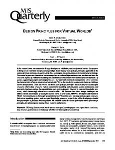
Figure 3: A synthesized eight-channel microphone signal is shown in the top panel. It represents a sound source which moves within one second from the left side of the array to the right hand side and back. The second panel shows the generating monophonic signal which is transmitted to the receiver with time varying wavefield parameters s0 and y, whose trajectories are plotted in the third panel. The bottom panel shows eight decoded signals.
where y is the distance of the source from the array and c is the speed of sound in air. The information rate is thus reduced to one generating signal and scalar wavefield parameters s0 and y. Correspondingly, encoding process would involve estimation of a source location, see, e.g., [29], and selection of a generating signal from a microphone which is closest to the source location. The generating signal could be coded using any monophonic audio coder. The performance of a simple coder based on this idea is illustrated in Fig. 3. The localization is based on estimation of time-delay of arrival (TDOA) using the PHAT algorithm [30, 29]. The generating signal is transmitted uncoded. The top panel shows eight signals from a linear microphone array corresponding to a stationary sound source moving very rapidly from left to right and back. The second panel shows how the generating signal Γ1 (n) is sampled from the microphone signals. This is coded using a monophonic audio coder. The third panel shows the trajectories of wavefield parameters. An eight-channel reconstruction is shown in the bottom panel of the figure. The coding algorithm is transducer invariant and the encoder/decoder system runs in real-time for up to 32 channels in an ordinary PC. This coder works relatively well in the case of well-behaving sources, e.g., speakers who do not interrupt each other or move very fast, in a low reverberation environment. But, it fails in more complex conditions. A comparison
of the top and bottom panels reveals that the coder produces some artifacts in this case of very rapidly moving source (4 m/s back and forth). Similar problems also appear at onset of a new sound source. In the case of a reverberant transmitting room the performance is even worse. The estimation of a source location suffers from reverberation but that is not a very serious limitation since the performance of a human listener in the same task degrades, too. The reverberation in the room is convolved with the generating signal but the reconstruction filters of (13) render it to the same location with the source signal. Therefore, the perceived room effect of apparent source width, see, e.g., [31], do not correspond to the amount of reverberation in the signal. The reconstruted wavefield sounds more like that of a reverberant source in a free field than a source in a reverberant field. 2.2. Subband coding Any of the techniques studied in the previous sections can be applied separately at different frequency bands. This type of processing is beneficial in many ways. At the time of writing this paper, the design of coding algorithms based on this principle is on-going work. Therefore only some central ideas are presented in this article. Input signals xm (n) are processed in frames so that each signal is decomposed into B frequency bands to form a spectrum vector given by [ξm1 (k) ξm2 (k) ξm3 (k) · · · ξmB (k)],
(14)
where k is the number of a signal frame. Typically spectrum vector is computed using FFT or MDCT. Transform bins are then grouped so that the frequency representation approximates the frequency scale of hearing. That is, ξmb (k) terms usually has more than one frequency bin and therefore it is actually a vector. However, this is omitted in the notation. In the simplest case, each subband b is processed separately. We may form another vector which now has the same spectrum terms from M input signal vectors: [ξ1b (k) ξ2b (k) ξ3b (k) · · · ξM b (k)]
(15)
From this point the encoding for a subband b can proceed using any of the techniques presented earlier. For example, we may apply single source in a free field (SSFF) coding principle at each subband. This would assume that there is a single source at each subband, hence the system could basically accomodate up to B non-overlapping narrow-band sources. The estimation of wave field parameters (such as s0 and y in (13)) would be less accurate and require a longer processing frame for subband signals than for full band signals. This could be partly solved by applying an iterative procedure where initial estimation at
AES 22nd International Conference on Virtual, Synthetic and Entertainment Audio
5
Aki Härmä subbands is followed by a refining step where subbands with similar estimation results are combined. Eventually, this would lead to grouping of subbands according to separable active sources. 3. CONCLUSIONS Acoustic opening is a system first proposed almost 70 years ago. The main idea is simply to place a large number, for example, forty microphones on one surface to record a wavefield in a transmitting room and use a large number of loudspeakers to reproduce the wavefield in a receiving room. Ideally, this would produce a subjectively perfect imitation for the case that there is only a mechanical opening between the two rooms. This has been cited in many tutorial articles in the last several decades as a superior approach for audio transmission. But at the same time, it has been said to be highly impractical due to the large number of audio channels. Progress in microphone technology, AD/DA converters, signal processors, amplifiers, and loudspeaker technology suggests that the hardware problem can now be solved using almost standard audio hardware. The remaining problem is at the level of digital representation and coding of multichannel audio data. A general formulation and theory of the coding problem was presented and it was shown how many traditional methods of multichannel audio coding fit into the framework. A central coding principle applied in this article was that the bitrate of a coder should be independent of the numbers of microphones and loudspeakers. This is called transducer invariance. Many different modifications and new approaches were introduced and compared. There are basically two extremes in the set of techniques. First, one may try to estimate the locations of sources and deconvolve the original signals they emit. This is called source separation approach. Secondly, one may try to restrict the problem to the level of the transducer array and try to parametrize the wavefield information independently of the locations of sources and acoustics of the transmission room. This is called wavefield coding. The first extremist plan falls into parts because of the difficulty of the separation problem, and its built-in assumption of the statistical independency of source signals. The second extreme approach would lead to a highly inefficient coding algorithm because it is not utilizing the obvious fact that there are separable sources in the signals. Therefore, it was proposed that an optimal multichannel coder would be based on a combination of both approaches, and efficient utilization of geometrical, acoustical, and psychoacoustical knowledge relevant to this application. A simple coder designed for a special case of a single source in a free field (SSFF) was developed to the level of a prototype. It is reasonable to claim that SSFF is per-
Acoustic openings ceptually the most important special case to which the spatial hearing mechanism has adapted to in the course of evolution. The coder is based on a location tracking algorithm. The transmitted bit stream consists of a single monophonic audio signal and two time-varying parameters corresponding to an estimate of a source location. This technique works relatively well in the case of well-behaving sources, for example, in a conference where people do not interrupt each other. However, the performance with multiple simultaneous sources is unsatisfactory. The coder also produces audible artifacts at onsets of a new sound source. The coder has very low complexity and low delay. The most promising approaches seem to be in the class of methods where different types of spatial processing techniques are applied at spectrally separated subbands. This approach has many benefits. First, it makes it relatively easy to apply spatial perceptual models to the coder. It also helps to resolve non-uniqueness problems which often emerge in different formulations of multichannel coding algorithms. The main disadvantage is that it tends to increase algorithmic coding delay. ACKNOWLEDGEMENTS This work has been supported by the Academy of Finland and graduate school GETA. This work was partly done while the author was with Lucent Bell Laboratories and, later, Media Signal Processing, Agere Systems. REFERENCES [1] W. B. Snow, “Auditory perspective,” Bell Laboratories Record, vol. 12, pp. 194–198, March 1934. [2] M. M. Boone, E. N. G. Verheijen, and P. F. van Tol, “Spatial sound-field reproduction by wave-field synthesis,” J. Audio Eng. Soc., vol. 43, pp. 1003– 1011, December 1995. [3] A. J. Berkhout, D. de Vries, and P. Vogel, “Acoustic control by wave field synthesis,” J. Acoust. Soc. Am., vol. 93, pp. 2764–2778, May 1993. [4] S. P. Lipshitz, “Stereo microphone techniques ... are the purists wrong?,” J. Audio Eng. Soc., vol. 34, pp. 716–744, September 1986. [5] J. Herre, K. Brandenburg, and D. Lederer, “Intensity stereo coding,” in 96th AES Convention, Preprint 3799, February 1994. [6] J. D. Johnston and A. J. Ferreira, “Sum-difference stereo transform coding,” in Proc. IEEE Int. Conf. Acoust., Speech, and Signal Proc., pp. 569–572, 1992.
AES 22nd International Conference on Virtual, Synthetic and Entertainment Audio
6
Aki Härmä [7] A. N. Akansu and R. A. Haddad, Multiresolution Signal Decomposition. Telecommunications, Academic Press, 1992. [8] S. Gannot, D. Burshtein, and E. Weinstein, “Signal enhancement using beamforming and nonstationarity with applications to speech,” IEEE Trans. Signal Processing, vol. 49, pp. 1614–1626, August 2001. [9] D. Yellin and E. Weinstein, “Criteria for multichannel source separation,” IEEE Trans. Signal Processing, vol. 42, pp. 2158–2168, August 1994. [10] S. Brix, T. Sporer, and J. Plogsties, “CARROUSO - an european approach to 3d-audio,” in AES 110th Convention Paper 5314, (Amsterdam, The Netherlands), p. 7, May 2001. [11] M. Wax, T.-K. Shan, and T. Kailath, “Spatiotemporal spectral analysis by eigenstructure methods,” IEEE Trans. Acoust. Speech, Signal Processing, vol. ASSP-32, pp. 817–827, August 1984. [12] Y. Q. Yin and P. R. Krishnaiah, “Om some nonparametric methods for detection of the number of signals,” IEEE Trans. Acoust. Speech, Signal Processing, vol. ASSP-35, pp. 1533–1538, November 1987. [13] B. D. Van Veen and K. M. Buckley, “Beamforming: A versatile approach to spatial filtering,” IEEE ASSP Magazine, vol. 5, pp. 4–24, April 1988. [14] D. H. Johnson and D. E. Dungeon, Array Signal Processing: Concepts and Techniques. Englewood Cliffs, NJ, USA: Prentice Hall, 1993. [15] L. J. Griffiths and C. W. Jim, “An alternative approach to linearly constrained adaptive beamforming,” IEEE Trans. Antennas and Propagation, vol. AP-30, pp. 27–34, January 1982. [16] R. Bellmann, Adaptive Control Processes: A Guided Tour. Princeton University Press, 1961. [17] W. Hartmann, “Listening in a room and the precedence effect,” in Binaural and spatial hearing in real and virtual environments (R. H. Gilkey and T. R. Anderson, eds.), ch. 10, pp. 191–210, Mahwah, New Jersey, USA: Lawrence Erlbaum Assoc Publ., 1997. [18] E. H. A. Langendijk, D. J. Kistler, and F. L. Wightman, “Sound localization in the presence of one or two distracters,” J. Acoust. Soc. Am., vol. 109, pp. 2123–2134, May 2001. [19] S. Haykin, Modern Filters. New York: Macmillan, 1989.
Acoustic openings [20] J. Makhoul, “Linear prediction: A tutorial review,” Proc. IEEE, pp. 561–580, April 1975. [21] G. C. Reinsel, Elements of multivariate time series analysis. New York, USA: Springer-Verlag, 2 ed., 1997. [22] H. Fuchs, “Improving joint stereo audio coding by adaptive inter-channel prediction,” in IEEE Workshop Appl. Signal Proc. Audio Acoust. (WASPAA’93), (New Paltz, New York, USA), 1993. [23] N. S. Jayant and P. Noll, Digital coding of waveforms. New Jersey: Prentice-Hall, 1984. [24] D. Mary and D. T. M. Slock, “Causal transform coding, generalized MIMO linear prediction, and application to vectorial DPCM coding of multichannel audio,” in IEEE Workshop Appl. Signal Processing Audio Acoustics (WASPAA 2001), (New Paltz, New York, USA), pp. 151–154, October 2001. [25] S.-S. Kuo and J. D. Johnston, “Astudy why cross channel prediction is not applicable to perceptual audio coding,” IEEE Signal Processing Letters, vol. 8, pp. 245–247, September 2001. [26] A. Härmä, U. K. Laine, and M. Karjalainen, “An experimental audio codec based on warped linear prediction of complex valued signals,” in Proc. IEEE Int. Conf. Acoustics, Speech, and Signal Processing, vol. I, (Munich, Germany), pp. 323–327, April 1997. [27] A. Härmä, M. Vaalgamaa, and U. K. Laine, “A warped linear predictive stereo codec using temporal noise shaping,” in Proc. Nordic Signal Proc. Symposium, NORSIG’98, (Denmark), pp. 229–232, June 1998. [28] C. Faller and F. Baumgarte, “Efficient representation of spatial audio using perceptual parametrization,” in Proc. IEEE Workshop Appl. Signal Processing, Audio and Acoust., (New Paltz, New York, USA), September 2001. [29] J. H. DiBiase, H. F. Silverman, and M. S. Brandstein, “Robust localization in reverberant rooms,” in Microphone arrays: Signal Processing Techniques and Applications (M. S. Brandstein and D. Ward, eds.), ch. 7, pp. 131–154, Springer-Verlag, 2001. [30] C. H. Knapp and G. C. Carter, “The generalized correlation method for estimation of time delay,” IEEE Trans. Acoust. Speech and Signal Processing, vol. 24, pp. 320–327, August 1976. [31] H. Kuttruff, Room Acoustics. London, UK: Spon Press, 4 ed., 2000.
AES 22nd International Conference on Virtual, Synthetic and Entertainment Audio
7