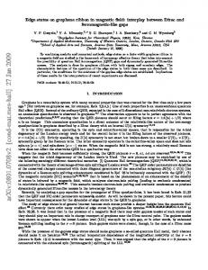
Coexisting multiple dynamic states generated by magnetic field in Bi2 Sr2 CaCu2 08+δ stacked Josephson junctions Yong-Duk Jin, Hu-Jong Lee,∗ and Gil-Ho Lee Department of Physics, Pohang University of Science and Technology, Pohang 790-784, Korea
A. E. Koshelev Materials Science Division, Argonne National Laboratory, Argonne, Illinois 60439, USA
arXiv:0910.4861v1 [cond-mat.supr-con] 26 Oct 2009
Myung-Ho Bae Department of Electrical and Computer Engineering, Micro and Natotechnology Laboratory, University of Illinois at Urbana-Champaign, Illinois 61801, USA Josephson vortices in naturally stacked Bi2 Sr2 CaCu2 O8+δ tunneling junctions display rich dynamic behavior that derives from the coexistence of three basic states: static Josephson vortex lattice, coherently moving lattice, and incoherent quasiparticle tunneling state. Rich structure of hysteretic branches observed in the current-voltage characteristics can be understood as combinatorial combinations of these three states which are realized in different junctions and evolve separately with magnetic field and bias current. In particular, the multiple Josephson-vortex-flow branches at low bias currents arise from the individual depinning of Josephson vortex rows in each junction.
Natural Josephson junctions (JJs), closely packed in an atomic scale, form along the c axis of highly anisotropic Bi2 Sr2 CaCuO8+δ (Bi-2212) superconductors [1]. Josephson vortices (JVs) are generated in these naturally stacked JJs in an in-plane magnetic field. Since the period between adjacent CuO2 bilayers, s (=1.5 nm), is much smaller than the in-plane component of the London penetration depth λab (∼ 200 nm), a Josephson vortex (JV) spreads over many junctions, which leads to inductive coupling between JVs. In stacked JJs, JVs fill every junction in a field higher than Bcr = Φ0 /(2πγs2 ) (∼0.75 T for Bi-2212), where γ (≡ λc /λab ∼250; λc is the out-of-plane penetration depth) is the magnetic anisotropy ratio. In this high-field region, JVs configurations in the static state are well understood and are known to be in a triangular lattice [2, 3, 4, 5]. Despite much interest, however, dynamic state of JVs is far less understood although various aspects of dynamical properties are proposed including the possible lattice structures [6, 7, 8], interaction between JVs and electromagnetic excitations[9, 10, 11, 12], and coherent characters of the JV motion [13] over the whole junctions in a stack. Key elements governing the dynamics of JVs are well reflected in the tunneling current-voltage (I-V) characteristics, which reveal the relation between the driving force acting on JVs in a junction by the bias current and the responsive JVs motion that induces a voltage drop across the junctions. For instance, JV viscosity is determined by the in- and out-of-plane quasiparticle dissipation that is extracted from the tunneling JV-flow resistance [14, 15]. Oscillatory tunneling magnetoresistance is also used to confirm the coherently moving JV lattice and the influence of the edge barrier potential on
∗ Corresponding
author:
[email protected]
the JV motion [16, 17, 18]. Interaction between JVs and electromagnetic excitations is another interesting subject of JV dynamics where the resonance with cavity modes appears as Fiske steps [12, 19]. Moreover, resonance between collectively moving JVs and plasma mode excitations in naturally stacked JJs has been studied extensively [9, 10, 11] where multiple subbranches in the I-V characteristics have been claimed to be an experimental evidence for the resonance[8]. The interaction between Josephson and pancake vortices (PVs) is also a high focus of recent studies [5, 20, 21, 22]. It has been demonstrated that the motion of PVs can be manipulated by the JVs via attractive interaction between them [23, 24, 25]. This suggests that the motion of JVs can alternatively be influenced by the PVs[5]. In this study we report that the JV-flow characteristics become a lot more diverse when pinning effect is introduced. In an in-plane magnetic field of ∼1 T on naturally stacked JJs, JVs are pinned down for a low bias current but get depinned separately in different junctions at a current higher than the depinning current. The pinning and depinning of JVs give rise to sub-branches in the I-V characteristics, which arise as a combination of three distinct junction states: static JV lattice, coherently moving lattice, and incoherent quasiparticle tunneling (IQT) state. With increasing in-plane magnetic field strength over 2 T, the sub-branches become separated from IQT branches due to reduction of the depinning current and form JV-flow branches (JVFBs). The coexisting multiple dynamic junction states are better resolved as the pinning of JVs by PVs is enhanced in a slightly tilted inplane magnetic field. It allows an unprecedented accurate access to JV dynamic states in the atomically stacked tunneling junctions. A comparison between the JV-flow and the zero-field IQT curves indicates that the coherently moving JVs form a triangular lattice configuration.
2 I.
EXPERIMENT
We prepared slightly overdoped Bi-2212 single crystals by the standard self-flux method [26]. Three rectangular stacks of junctions sandwiched between two gold-layer electrodes were fabricated [see the insets of Fig. 1(c)] by using the double-side cleaving technique [27, 28] in combination with the electron-beam lithography and the thermal evaporation. The superconducting transition of the c-axis tunneling conductance at Tc (=87 K) indicates the oxygen doping concentration [29] to be ∼0.19. The lateral size of the three samples was 1.5 × 10 µm2 , which was in the long-junction limit as the length was longer than the Josephson penetration depth λJ (= γs ∼ 0.3 µm for Bi-2212). An in-plane external magnetic field was applied perpendicular to the long side of a sample. We report on the typical c-axis tunneling I-V characteristics from one of the samples, which arose from the tunnelingcurrent-driven JV-flow dissipation. The total number of junctions N was determined to be 23 from the number of zero-field IQT branches [30] in the inset of Fig. 1(a) (the suppressed two lowest-voltage branches are from the surface junctions with the reduced Josephson coupling [26]). The contact resistance (∼10 Ω) included in our two-probe measurements can be safely neglected as it is about two orders of magnitude smaller than the tunneling resistance of each junction. The sample was field cooled without a bias current whenever the field strength or the field angle was altered. The in-plane field direction was tuned within the accuracy of 0.01◦ by finding the angle for maximum JV-flow resistance at temperature around 65 K while controlling a stepper motor placed at room temperature. As the pinning on JVs by PVs is minimized at the best-aligned field angle the JV-flow resistance becomes maximum.
II.
RESULTS AND ANALYSIS
Figure 1 shows the gradual variation of the I-V curves for H varying from 1 to 3 T, where the fields were best aligned to the in-plane direction. In a low magnetic field of 1 T [Fig. 1(a)] the IQT branches remain conspicuous with critical switching currents much reduced from the zero-field values shown in the inset of Fig. 1(a) for all the branches. For this field value, one also notices the development of tiny kink structure with some indistinct subbranches for I ∼ 10 µA, which will be discussed in detail below. For 1.2 T, subbranches develop around the kink so that branching becomes very crowded [Fig. 1(b)]. With further increasing field these subbranches move to a lower-bias current region and get separated from the IQT branches for higher bias currents [Figs. 1(c) and (d)]. It will be shown below that the subbranches are directly linked to the JV motion and thereby constitute the JVFBs. It has been suggested [9, 10] and claimed to be confirmed [8, 31] that the collectively moving JVs in stacked JJs resonate with transverse Josephson plasma
modes, which generates the multiple JVFBs. But, with increasing the in-plane magnetic field the switching currents in JVFBs keeps shrinking [see Fig. 1(d) and its inset]. The JV resonance picture does not predict the field dependence of the switching current so that this trend cannot be explained by the JV resonance picture [9].
FIG. 1: (colour online) (a)-(d) Magnetic-field dependence of the Josephson-vortex-flow (JVF) I-V curves at 4.3 K for the best-aligned planar fields of 1 to 3 T. Inset of (a): zero-field quasiparticle branches in tunneling I-V curves. Inset of (b): close-up feature of the low-bias subbranching for 1.2 T. Insets of (c): (left) scanning electron microscopic picture of the sample stack, (right) schematic measurement configuration. Inset of (d): JVF branches for fields of 4, 5, and 6.5 T. The arrows in the insets of (c) and (d) denote the depinning currents (see the text for details).
Figure 2 illustrates the close-up details of Fig. 1(a) for 1 T (red and green curves), together with the zero-field IQT curves (gray ones). The red and green curves are bordered around I∼10 µA. In the low-bias red-curve region the 1 T branches are in exact coincidence with the zero-field IQT branches. This implies that JVs are completely pinned down without showing any JV-flow voltages and thereby constitute the static-vortex state [32]. This also implies that the magnetic field very weakly influences the resistive junctions. As one moves to more right branches, junctions containing static JVs (thus, in the zero-voltage state) turn into the IQT state one by one (see the lower schematic JV configurations), causing the voltage jumps between neighboring branches. On the other hand, the green-curve region represents the dynamic-vortex state, where the JVs are depinned by a higher bias current and thus each IQT branch is shifted by the corresponding JV-flow voltage as denoted by blue arrows for some branches. The inset of Fig. 2 shows the voltage difference (Vdif f ) between a zero-field IQT branch and the corresponding branch in 1 T for each value of m at the given bias currents. The branch index m denotes the number of junctions containing dynamic vortices. For I=8 µA in the red-
3
FIG. 2: (colour) Detailed I-V curves in an in-plane field of 1 T (red and green curves) along with the zero-field IQT (grey) curves. Schematic vortex configurations corresponding to a few branches are illustrated. Inset: the voltage difference (Vdif f ) between neighboring in-field and zero-field branches for each m for the given bias currents. The line is a guide to the eyes.
curve region, Vdif f almost uniformly vanishes, supporting that the JVs in all the junctions are static in this region. For I=16 µA in 1 T, on the other hand, Vdif f rises linearly with increasing m, satisfying the relation Vdif f = Vm (H; I) − Vm (0; I) = mδV (H, I). This indicates that, as more junctions turn into the dynamicvortex state, all the depinned JVs move with a uniform velocity, which is consistent with the previous studies on the Shapiro step response in the coherent JV-flow state [13]. Here, δV (H, I) (e.g., 0.44 mV at 16 µA) is the average JV-flow voltage contribution of each junction for a given field and a current. Thus, the kink near 10 µA in the 1 T I-V curves represents the boundary between the regions of static JVs (showing pure IQT branches) and the dynamic JVs (showing branches of IQT and moving JVs). In Fig. 2, the static-JV state (red curves) for high m values abruptly turns into the corresponding dynamic-JV state (green curves). But, in fact, the fine subbranches near the kink seen in Figs. 1(a) and 2 signify the gradual transition between the two JV states as JVs are depinned separately in each junction. Each subbranch corresponds to different number of junctions containing moving JVs. Subbranches become clearer for a slightly higher magnetic field of 1.2 T as seen in the inset of Fig. 1(b). Here, a higher-m branch has more combinatorial configurations of junctions with static and dynamic JVs. That causes a branch located more left to split into a higher number of subbranches as in the inset of Fig. 1(b). With increasing fields these subbranches become separated from IQT branches, developing into the JVFBs in higher magnetic
field above ∼2 T [Figs. 1(c) and (d)]. This feature can be qualitatively understood if one assumes that the main pinning force acting on JVs, in this relatively low inplane field range, is from any field-independent pinning sources[32]. Then the total Lorentz force on JVs in a bias current increases for a higher in-plane field as more JVs are introduced to a junction while the pinning force remains insensitive to the in-plane field strength. In consequence, the subbranches move to a lower-bias current region and get separated from the IQT branches when the depinning currents [denoted by the arrows in Fig. 1(c) and (d)] become smaller than the retrapping current of the JJs, at which the junctions in the IQT state turn into the Cooper-pair tunneling state. Detailed development of the JVFBs is more clearly demonstrated in the presence of pancake vortices (PVs). A PV in a superconducting CuO2 plane, which can be easily pinned down by defects in a crystal such as the oxygen vacancies, tends to exert a pinning force on adjacent JVs by the attractive interaction [5, 33]. Figures 3(a)– (d) illustrate the variation of the JV-flow I-V curves with slightly tilting the sample stack with respect to the bestaligned in-plane position in 4 T. The JVFBs extend with increasing the c-axis field component H(c) along with the slight increase of the tilt angle [H(c) =350 Oe for θ=0.5◦ ]. The shape of the JVFBs was highly symmetric with respect to θ=0◦ (not shown). For a higher tilt angle, larger bias currents are required to depin JVs from the increased population of PVs, which extend the JVFBs into a higher bias current region. This PV-pinning effect on the JVFBs was also reproduced as the PVs were generated in a low c-axis-oriented field (an order of a few tens Oe) by a separate Helmholtz coil with the main solenoid at the best-aligned in-plane field position (not shown). Once a JV is depinned, the PVs exert a far less effect on the JV motion for low tilt angles although the presence of higher-density PVs in a higher tilt angle may slow down the JV motion [5]. This bears an analogy with the fact that the dynamic friction coefficient is much smaller than the static one. Thus, JVFBs for two different field angles almost overlap as seen in Fig. 3(e). In this situation, as the depinning current increases for a higher tilt angle, the maximum voltage at the switching current of each JVFB is also enhanced. But, this feature is in contradiction to the picture of the resonance of JVs with the transverse plasma modes [9] as the cause of branching of JV-flow IV curves. In this picture, the switching voltage between branches corresponds to the resonant propagation mode velocity of the transverse Josephson plasma excitation. For a fixed value of an in-plane field with a constant JV number density, the switching voltage should be insensitive to H(c) as the resonant mode velocity, which is proportional to ωp × λJ (ωp ; Josephson plasma angular frequency) [11], is independent of the Josephson critical current Ic . As θ exceeds 0.4◦ [Fig. 3(d)], the branch structure is modified considerably so that JVFBs become much more pronounced and extend into the “IQT-branch region”,
4
FIG. 3: (colour online) (a)–(d) Progressive variation of the Josephson-vortex(JV)-flow I-V curves measured at 4.5 K as the sample stack is slightly tilted up to θ=0.5◦ from the inplane field position in 4 T. (e) A comparison of JV-flow I-V curves for H=4 T at the best-aligned position and at θ=0.2◦ . (f) Different JV regimes for the near-planar field of 4 T, as a function of c-axis field component of up to 350 Oe (or θ=0.5◦ ).
which will be referred to as “extended-JV branches”. As it will be discussed in detail below, this extended-JV branches arise from the combined distribution of junctions with static JVs and the ones in the IQT state. Figure 4 illustrates JV configurations of Fig. 3(d). The lowest-voltage single branch (for I