University of Califomia, Los Angeles ... Los Angeles, CA 90095-1594, U.S.A. .... signal pmcessbg, showing error-free recovery of the transmitted data. Stream.
*+> 271, the phase of Hij can be considered a random variable uniformly distributed
The wireless channel
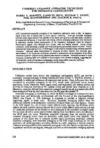
Block diagram of a 2x2 COMIMO system showing two independently modulated optical cmiers and two receivers.
Fig. 2.
..
’.
,*.
Multimode Fiber (MMF)
Fig. I .
(a) A 2x2 MIMO communication system. XI. XZ. Y I , Y l . ZI. and 2 2 represent symbol ~ ~ n s t e l l a t iato ~different stages. (b) Multimode fiber can a150 be regarded as a channel wi!h multipaLh
divenity.
over [0,2v]. and /H,3/ is modeled as a Rayleigh distributed random variable. The Rayleigh flat fading model described above is the worst scenario in traditional singleinput single-output (SISO) systems, but turns out to he the best for MIMO systems [3]. The analogy between multimode propagation in MMF and mutipath scattering in wireless channel (Fig.]) is pointed out by H. R. Stuart first, using the term dispersive multiplexing and modal-coupling diversity. Feasibility of MIMO over MMF is demonstrated in [4] with a 2 x 2 experiment setup (N=M=2) operating at 1 Mbit/s per channel. Unless a precise channel model H is available a priori (this is seldom the case), MIMO signal processing requires detection of both intensity and phase information, in contrast to pure intensity detection used in conventional fiber optic links. In [4]. RF subcarrier (-1 GHz) modulation with PSK data format was used in the transmitter, followed by recovery of In-phase (1) and Quadrature (Q) RF components through synchronous RF demodulation in the receiver. Recalling the diversity requirement ( u r d >> Za), the use of RF subcarriers requires a much longer delay spread and hence, longer linklength to ensure a rich-scattering channel as opposed to optical carriers, since wept B w l f . For example, when a I-GHz RF subcarrier is used in a 62.5-pm fiber system operating at 850 nm, independent Rayleigh statistics are realized for fiber longer than -1 km. In contrast, if an optical carrier is used in a coherent system, sufficient diversity exists even in a I-mm link. 111. EXPERIMENTS AND RESULTS
We have built a proof-of-concept 2 x 2 coherent optical MIMO system, as shown in Fig.2. A 1545-nm laser output is split into two separate arms which are BPSK
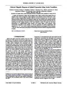
modulated by two independent data streams respectively, using standard LiNbOs modulators. A MMF directional coupler is used to combine two input arms into a single 62.5-pm fiber (100-m long) before another 3-dB coupler is used to separate and direct two different outputs to two detectors. Each input is coupled to the MMF with a slightly different modal power distribution. Furthermore, the sequence of MMF launching, beam combining, and splitting, creates a natural tendency for each detector to receive power from both transmitters via a differem dishibution of modes. For coherent demodulation, the necessary local laser oscillator (LO) signal is derived from the original narrowlinewidth laser source to ensure phase and frequency locking. The transmitted signal, S, and local oscillator. L, are directed into the commercial Lithium Niobate Quadrature optical hybrid which gives two pairs of outputs (I)S+L,(Z)S-L, and (3)S+jL,(4)S-jL. (1),(2) and (3),(4) are collected by two balanced detectors. This provides the full signal space information of the baseband signal, i.e. both I and Q components. These are digitized and applied to the signal processing algorithm for MIMO symbol recovery. The system runs at a bit rate of 100 Mbit/s per channel, and all signal processing is done offline in the computer program. MIMO signal processing consists of two steps: (i) estimating the channel matrix H using a sequence of training symbols, and (ii) using the channel estimate to recover the transmitted symbols. In this work, we have used the V-BLAST MIMO algorithm described in IS]. Fig.3(a) shows the complete signal space constellations for two receivers in a 2x2 COMIMO system where 100 m of 62.5-pm MMF is used. The four clusters of points in the constellation diagram, corresponding to transmitted symbol pairs (l,l},(1,~1},{~1,1},{-1,-1}, manifest the transmitter modal-coupling diversity If sufficient diversity does not exist, the symbol pairs 1-1, l } and {-1, -1) will overlap in the constellation and will not be distinguishable. The fact that they are distinguishable in Fig.?(a) indicates that sufficient transmitter diversity is achieved. Furthermore, modal-coupling diversity present at the receivers causes the constellations for the
VBLAST Recovered
Received
Channel 1 .:
d
-?*
vmu*n*.W-e.ir")
2!
I-.*NI.nMUd.irY.I
(a)
.I
D
l
2
cru..Wm