Samsung and 3D Xpol/Arisawa LCD by Hyundai. Auto-stereoscopic displays, however, ... figure shows how views are spatially distributed on a multiview screen.
Coherent Spatial and Temporal Occlusion Generation R. Klein Gunnewieka , R-P. M. Berrettya , B. Barenbrug, and J.P. Magalhãesb a Philips b Philips
Research Eindhoven, High Tech Campus, 5656AE Eindhoven, Netherlands 3D Solutions Eindhoven, High Tech Campus, 5656 AE Eindhoven, Netherlands ABSTRACT
A vastly growing number of productions from the entertainment industry are aiming at 3D movie theatres. These productions use a two-view format, primarily intended for eye-wear assisted viewing in a well defined environment. To get this 3D content into the home environment, where a large variety of 3D viewing conditions exists (e.g different display sizes, display types, viewing distance), we need a flexible 3D format that can adjust the depth effect. Such a format is the image plus depth format in which a video frame is enriched with depth information of all pixels in the video. This format can be extended with an additional layer for occluded video and associated depth, that contains what is behind objects in the video. To produce 3D content in this extended format, one has to deduce what is behind objects. There are various axes along which this occluded data can be obtained. This paper presents a method to automatically detect and fill the occluded areas exploiting the temporal axis. To get visually pleasing results, it is of utmost importance to make the inpainting globally consistent. To do so, we start by analyzing data along the temporal axis and compute a confidence for each pixel. Then pixels from the future and the past that are not visible in the current frame are weighted and accumulated based on computed confidences. These results are then fed to a generic multi-source framework that computes the occlusion layer based on the available confidences and occlusion data. Keywords: image-plus-depth, inpainting, occlusion layer, multi-source framework
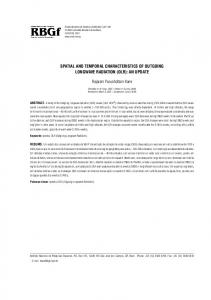
1. INTRODUCTION To enable stereoscopic depth perception, several technologies have been suggested that allow different images to be provided to each eye. Most of them use special glasses∗ . Glasses based solutions exist in for example 3D Ready DLP by Samsung and 3D Xpol/Arisawa LCD by Hyundai. Auto-stereoscopic displays, however, take a different approach: a different image is provided to each eye without the need of special eye wear. Philips has developed a product line of multiview auto-stereoscopic 3D displays.1 The display offers its different views through the use of a film of lenticular lenses in front of the screen. See Figure 1 for details. Other examples of auto-stereoscopic displays are Newsight barrier displays.2
(a)
(b)
Figure 1. Left figure shows a multiview LCD. Special attention is given to the lens system. Right hand figure shows how views are spatially distributed on a multiview screen.
Philips’ multiview auto-stereoscopic displays can show a high number of different views (e.g. 9) at a given moment in time. This fact not only creates a stereoscopic effect but also allows the user to experience horizontal parallax, by moving his head horizontally. Figure 1 (b) shows how the different views are spatially distributed. ∗
Polarized or shutter glasses, for example.
In general, current multiview displays strongly differ in the number of views, pixels and depth reproduction capabilities. Furthermore, the amount of depth perceived depends on viewing distance and display size as well. In should be noted that, for stereoscopic displays, depth perception depends on display size and viewing distance as well. Therefore, a display indepent interface format, that enables adjustment of the depth effect, is required. The preferred display independent input format for home 3D displays is the image-plus-depth format,3–5 which has been standardised in MPEG-C part 3. Being independent of specific display properties, such as number of views, view mapping on pixel grid, etc., this interface format allows optimal multiview visualisation of content from many different sources, while maintaining interoperability between display types. To be more specific, the image-plus-depth format is an extension of the conventional video format. It specifies for each sample point in the input images not only information about the color, but depth related data as well. However, the majority of (legacy) video content is 2D, hence video captured from a single viewpoint. Furthermore, a growing number of new 3D productions from the entertainment industry are aiming at 3D movie theaters that use a stereo format, primarily intended for eye-wear assisted viewing. This content does not have associated depth related data. Thus, in order to be display independent and flexible, the content should be converted to the image plus depth format, hence each pixel should be annotated with a depth value. Obtaining depth data from existing video content has been researched extensively. Various algorithms have been presented that generate depth data for existing video content either from multiview/stereoscopic content6, 7 or from 2D video content.8, 9 Most of these algorithms are based on automatic generation of depth maps. There are, however, also many algorithms that are user assisted and generate high quality depth maps. The image plus depth format can be extended with additional layers to improve the quality of the render views. Such a layer could be a transparency layer/alpha map.10 An implementation of such a transparency layer/alpha map is discussed in a paper,11 that will be presented at this conference as well. In this paper we will focus on another additional layer, the occlusion layer, that resolves pixels that are not visible in the centre view. We will refer to algorithms for occlusion data generation as inpainting algorithms. There are various methods to generate occlusion data. Basically these methods can be grouped into three classes. Firstly, the occlusion data can be derived from other locations within the image. This class of inpainting algorithms is typically applied in the field of image restoration. These inpainting algorithms generate not “real” occlusion data, but make up occlusion data based on local image characteristics. Secondly, the occlusion data can be obtained from other views if the scene is captured by either a stereo12 or a multiview camera system. This class of inpainting algorithms obtains “real” occlusion data captured from a different viewpoint with a different camera. Thirdly, the occlusion data can be retrieved along the temporal axis, from the past and/or future images. This class of inpainting algorithms uses “real” data from different time instances. The inpainting method described in this paper belongs to the third class. Furthermore, we discuss the framework in which we use this temporal inpainting method. As stated above, there are multiple methods for inpainting. In order to merge the output of the various inpainting methods into one occlusion layer, a generic multi-source framework is in place. This framework merges the various occlusions based on their respective confidences, resulting in an occlusion layer.
2. RELATED WORK A variety of application fields exist in which unresolved pixels are recovered. Some application fields are image enhancement, photo restoration, image coding, error concealment for image transmission, object removal and of course 3D rendering. † Some of these inpainting methods can be used in the context of occlusion layer generation for 3D as well. We will discuss various inpainting methods in more detail along the aforementioned three classes. The first class exploits the local neighbourhood. This class is typically applied to still images. These inpainting techniques are classified as structural, textural or hybrid approaches. Structural inpainting techniques are usually based on partial differential equations that aim at recognizing edges arriving at occlusion/hole boundaries and continuing them.13, 14 Texture synthesis tries to recognize textured areas in the image and replicate them into the occluded parts.15, 16 Both techniques do have their flaws. Hybrid methods try to combine the best of both, structural and textural.17, 18 Still image †
Due to the various application fields a nomenclature exists that is far from homogenous. Hidden texture generation, constrained synthesis, error concealment, hole filling, retouching and occlusion filling are all names for recovering data.
inpainting techniques can be used for video sequences as well, however extra constraints apply. Constraints like temporal stability and complexity of the algorithm will be posed on these algorithms. Temporal instability in the occlusion layer will appear as flickering in the content during rendering, which is an annoying artefact. Therefore we put emphasis on temporal stability of the occlusion layer. The second class of inpainting methods obtains occlusion data from multiple viewpoint input sequences, hence a scene is captured with multiple cameras (N). To do so, the disparity between the various viewpoints is first estimated. Then the views are warped to one predefined viewpoint. During warping a number of pixels will be mapped on top of each other. The ones with the largest normalized disparity value will become foreground, whereas the others are assigned to background layer(s).19 Normalization of disparity values is needed to be able to relate the disparities to the various viewpoint pairs. Since in the stereo case (N=2), there is just one pair, normalization is implicit. The third class exploits the temporal axis; parts of the video that are not visible in the current frame can be visible in past or future frames. This class is used in various application fields of 2D video processing, for example error concealment, video coding and removal of undesired objects from video. We touch upon some of these methods and relate those to our application field. In the context of MPEG-4 coding, a method has been presented that robustly estimates the background.20 This algorithm derives the background scene using the camera motion. This algorithm performs fairly well, although it can not deal properly with (small) moving object and non-stationarities in the background. Kokaram et. al. presented a method for automatic rig removal.21 This method is based on an optical flow motion estimation process in a Bayesian framework. Trials with films have been conducted, however it does not seem to acount for fast movements in the background, lighting changes, etc which make the inpainting process harder. One way to deal with these changing conditions is to use confidence based methods. Such a method has been described by Oliveira.14 That method generates a background layer using a confidence based method, trying to retrieve the missing data first from the temporal axis and then from the spatial information, similar to the generic multi-source framework we propose. Wexler et. al. present a space-time completion algorithm that reconstructs the missing parts in a video sequence by using cubic windows.22 So, rather than a 2-dimensional window, a 3-dimensional window is used for the reconstruction of the missing data which seems a smooth manner to imply temporal consistency. From a computational point of view, however, this solution seems extremely complex. Therefore, in this paper, we present an algorithm that uses parts of space-time completion algorithm, yet is much less complex.
3. ALGORITHMS As explained above there are multiple axes along which the occlusion data can be generated. Typically each technique will provide results at various quality levels for each kind of video sequence: temporal inpainting performs better in low motion sequences but with possibly complex backgrounds, spatial inpainting performs better in small holes on simple backgrounds, etc. In order to perform well over such a multitude of video sequences we devised a generic multi-source framework that enables proper combination of separate occlusion generation techniques. This generic multi-source framework is schematically depicted in Figure 2. The image plus depth data together with a hole mask, which indicates where occlusion data should be generated, are fed into this framework. Occlusions annotated with confidence values are generated via multiple paths (spatial, temporal, stereo, etc.) and are mixed to one occlusion plus depth layer. As indicated in the previous section, a lot of research has been conducted on generation of occlusion data from a local neighborhood (spatial). Last year we have presented occlusion generation from stereo input,23 whereas in the remainder of this section we will discuss our temporal inpainting algorithm.
3.1 Temporal inpainting A diagram presenting the schematic data-flow for the algorithm can be seen in Figure 3. Before starting the temporal inpainting process, motion estimation is performed, resulting in a vector field that will be used in the inpainting process. Furthermore, a foreground mask is determined from the depth map to indicate where occlusion data should be generated and which parts of the video should not be used for inpainting. The inpainting algorithm starts by computing the border of
Figure 2. Diagram of multi-source framework.
each foreground object by using an onion-peeling strategy‡ . Then it iteratively applies the following strategy to each pixel p: 1. Determine where to find the reconstruction: look in the motion estimation vector field for a nearby region belonging to the background. Get the motion vector (vx , vy ) from this region. If the search fails to find a background motion vector then assign to this pixel a confidence of zero and proceed to the next pixel. 2. Look in the buffer for the first candidate c, which is a non-occluded pixel with coordinates (x + k ∗ vx , y + k ∗ vy ), where k is the buffer frame distance to the current frame (positive for future frames, negative for past frames). If no pixels are found in the temporal buffer then assign to this pixel a confidence of zero and proceed to the next pixel. 3. If any such pixel c is found (either in the past buffer, future buffer or both), proceed with the local search: 1. For each of the pixels in a two-dimensional (sx , sy )-sized area around this candidate pixel c, get the (wx , wy , wz )sized three-dimensional window Wc centered around it. 2. Construct also a (wx , wy , wz )-sized window Wp around p, called the reference window. 3. Store each possible reconstruction for the (sx , sy )-sized area along with its comparison result, based on the (wx , wy , wz )-sized windows, in a buffer. A modified sum of absolute difference (SAD) comparison is performed between the (wx , wy , wz )-sized window around p and the candidate pixel. Occluded pixels in these windows are treated separately. This will be explained in more detail in Equations 1,2. 4. Mix all possible reconstructions into a single value, using a weighted average where the weight is given by a negative exponentional function described later on. ‡
We use this inpainting order to force any errors to propagate towards the center of the foreground objects, since there they will probably not be visible.
5. Set a confidence level for this pixel. The confidence is based on the comparison results for the best reconstruction, best. This comparison result is inversely proportional to the confidence level. 6. Blend the result with the value from the previous frame using Equation 5.
Figure 3. Diagram of the Motion Assisted Forecasting Background sub-components.
After all pixels in one onion-peel layer are visited, the algorithm recomputes the border and repeats the above process, until all pixels are visited or until a maximum number of layers has been processed. The settings of the parameters determine how well the algorithm performs and how complex, in terms of computations and memory requirements, the algorithm is. Parameters (sx , sy ) in the description above defined the width of the local search areas around the pixel in the buffer. Increasing its size will considerably increase the running time of the algorithm, but will allow for a more robust reconstruction. Changing the values of (wx , wy , wz ) will also change the quality of the reconstruction. If the area to be reconstructed is highly detailed (like a texture), then small windows should be enough to select the best reconstruction. If this is not the case, increasing the window size will help in finding the best reconstruction. This is especially the case for the spatial dimensions wx and wy , since wz relates mostly to sensitivity to the temporal differences. Note that the pixel comparisons, for each reconstructed pixel, will be sx ∗ sy ∗ wx ∗ wy ∗ wz . A typical value (and the one set by default) would be 5 for each of these constants, amounting to 3125 pixels (25 windows). This number will be doubled if a match is found both in the past and in the future frames. To obtain sufficient occlusion data typically quite some frame memories are required. In our experiments we have used frames of up to 50 frames apart from the current frame. The comparison function used in step 3.3 of the algorithm is a modification of the widely used Sum of Absolute Differences (SAD):
Compwindow (Wp , Wc ) =
w y wz 4 wx X X XX
Comppixel (Wp (x, y, z, k), Wc (x, y, z, k))
(1)
x=1 y=1 z=1 k=1
( |a − b| Comppixel (a, b) = penalty
if both pixel a and b belong to the background otherwise
(2)
In Equation 1, wx , wy and wz are the respective parameters for the width, the height, the temporal depth of the cubic window. Whereas k represents four pixel components: either luminance, chroma U and V and depth, or red, green, blue and depth. In Equation 2, penalty is a standard value that is added to the result in case the comparison cannot be performed due to lack of data. All posible resonstructions are mixed using a weighting function. Mixing allows the algorithm to be much more flexible in terms of using different reconstruction sources: irrespectively of how the reconstruction was generated, all it needs is a color value and the result of the comparison for its associated window. Any number of possible reconstructions can be mixed, and, even if only very few are of good quality, the outcome will always favor the ones with the best results. The weighting function for the mixing is a negative exponential function and is given by: f (w, mixFactor, worst, best) = 2−10
1−mixingFactor
(worst − best)(− best +x)2
,
(3)
where w is the comparison result, mixFactor is a user-definable parameter and worst and best are respectively the highest and lowest comparison result stored from the previous step. A graphical representation of the function is shown in Figure 4(a), fixing worst and best to some typical results and plotting over w and mixFactor. The graph shows that increasing the mixFactor will lead to higher contribution factors for reconstructions with lower comparison result. This will increase blurriness in the reconstruction, which is likely a desired effect if the confidence on the result is not very high.
(a)
(b)
Figure 4. (a) 3D plot of the mixing function. (b) Confidence map for the reconstructed mobile sequence.
Finally, we normalize the result according to the number of effectively compared pixels. As a result, lacking data for a few pixels will hardly affect the comparison result, whereas lacking data for a significant amount of pixels will affect the comparison results greatly. An important feature of an inpainting algorithm is the ability to provide some feedback on how confident it is about the inpainting quality. One can imagine that if the confidence is low, other inpainting techniques could do better. Therefore, we compute a confidence associated to each inpainted pixel that is inversely proportional to the comparison function (best). Furthermore, we introduce some reserved values for signalling.
255 conf = 254 − best 0
if the pixel belongs to the background if the pixel was inpainted if there is no suitable match
(4)
The resulting effect can be seen in Figure 4(b). The brighter the pixel is the higher the confidence is. The confidence measure is not only affected by the complexity of the reconstruction but also by the temporal distance to the reconstruction. In the case where the motion is monotonous in direction (like in this example), the confidence will also decrease naturally as we progress inside the hole, which is a desired effect. Even though the reconstruction follows the same pattern for every frame, the area to reconstruct might change, and the temporal buffer will definitely change, thus affecting the outcome of the algorithm. This makes sudden changes possible in the reconstruction from one frame to the next one. These changes can for instance be caused by new, uncovering of background data in the temporal buffer. We do know, however, that temporal consistency is very important in the perceptual quality. A way to enforce temporal stability is to keep the previous frame’s reconstructed background, motion compensate it, and blend the new results with the old ones. This is implemented through a recursive filter operation: pt = (1 − b) ∗ pt−1 + b ∗ rt
(5)
pt is the value of the pixel at the current frame t, pt−1 is its value on the previous frame (t − 1), rt is the reconstruction found for the pixel, and b is the blending parameter, which can vary from 0 to 1 (higher values will blend the new results faster). Using Equation 5 results in a smoothing of the reconstruction generally improves the overall results.
4. DISCUSSION & RESULTS We have tested our generic multi-source framework on various sequences. An example is depicted in Figure 6, in which the occlusion generation process has been schematically depicted by means of resulting images. Three inpainting methods are depicted in this figure, that is inpainting from multiple viewpoint data, spatial and temporal inpainting.
(a)
(b) Figure 5. Temporal inpainting example, (a) image plus depth (b)occlusion plus depth.
The three images at the top represent the original sequences, whereas each of the three middle ones represent the result of an inpainting method. The image at the bottom represents the final result. It could be observed that the image representing the temporal inpainting is slightly better that the image representing the final, mixed, result. This illustrates that the algorithm sometimes produces somewhat less quality occlusion data in trade for better temporal consistency.
Figure 6. Example images of multi-source reconstruction mixing.
During testing we have seen that our temporal inpainting algorithm gives good results for a variety of sequences. An example is depicted in Figure 5. In the upper part (a) we have depicted the original image-plus-depth map for the pinocchio sequence, whereas in the lower part (b) we have depicted the occlusion and associated depth map that we have generated using our temporal inpainting algorithm. The nose of pinocchio has almost completely disappeared and the inpainted data resembles the background data well. It should be noted that the body of pinnocchio has hardly any disparity with the background and therefore temporally generated occlusion data between pinnocchio and the floor is not really needed. Other techniques for inpainting small areas of unresolved pixels will do. Furthermore, the occlusion data is temporally stable, which cannot be shown in this paper. We did observe that when the motion is very irregular the occlusion data that is generated is of a lesser quality. In such cases, the confidences for this occlusion data are lowered as well. Therefore, during the mixing process of the multi-source framework this occlusion data is almost completely filtered out. Moreover,
we did observe that we almost never obtain the exact ground truth occlusion data, but at the same time the algorithm never makes huge mistakes. This is due to the settings we have chosen. These settings are optimal for our 3D application, but for other applications, different settings could apply. The resulting occlusion data is typically a lowpass filtered version of the ground truth occlusion data. The amount of filtering is indicative for the confidence the algorithm has for its occlusion data. For the example presented in Figure 5 the confidences where high resulting in a sharp background image. Our algorithm requires frame memories to store frames from future and the past. In our experiments we have used up to 50 frames memories to both side. This memory usage makes an realtime solution is inpractical. Nevertheless, in comparison to the algorithm presented by Wexler et.al.22 the number of computations are significantly less, since we are not performing a (hierarchical) fullsearch, but rather a vector based approach. The processing time for a frame is in the range of seconds on a typical desktop PC. Therefore this algorithm can be used in an automatic offline occlusion generation tool.
5. CONCLUSIONS In this paper we have presented an algorithm to generate occlusion data from the temporal axis. Due to the confidence based approach we have seemless transitions, which results in temporally stable behaviour of the occlusion data. We can adjust the temporal behaviour by modifying some settings. For our 3D application temporal stability is crucial and as a result the occlusion data is low pass filtered in areas where the confidences are low. Furthermore, we have presented a generic multi-source framework that generates an occlusion layer based on confidences. There are no binary decisions on which inpainting method to use, which improves the temporal consistency. Thus this is an elegant and temporal consistent method to combine multiple inpainting methods for generating occlusion data.
REFERENCES 1. “Philips lenticular autostereoscopic 3d display http://www.philips.com/3dsolutions/.”
2. “Newsight barrier displays http://www.newsight.com/.” 3. C. Fehn, “Depth-image-based rendering (DIBR) compression and transmission for a new approach on 3D-TV ,” in Proc. Stereoscopic Displays and Applications, 2004. 4. B. Barenbrug, “3D throughout the video chain,” in Proceedings of Int. Congress of Imaging Science, pp. 366–369, 2006. 5. W.H.A. Bruls et. al., “Enabling introduction of stereoscopic 3D video: compression standards, displays and content generation,” in Proceedings of Int. Conference on Image Processing, pp. 89–92, 2007. 6. D. Scharstein and R. Szeliski, “A taxonomy and evaluation of dense two-frame stereo correspondence algorithms,” International Journal on Computer Vision 47, pp. 7–42, April-June 2002. 7. Yang, L. Q. Wang, and a.o., “Stereo matching with color-weighted correlation, hierarchical belief propagation and occlusion handling,” in Proceedings of the Conference on Computer Vision and Pattern Recognition, 2, pp. 2347– 2354, 2006. 8. A. Torralba and A. Oliva, “Depth estimation from image structure,” IEEE Transactions on pattern analysis and machine intelligence 24, pp. 1226–1238, 2002. 9. M. Han and T. Kanade, “Multiple motion scene reconstruction with uncalibrated cameras,” IEEE Transactions on Pattern Analysis and Machine Intelligence 25, pp. 884–894, 2003. 10. S. Hasinoff, S. Kang, and R. Szeliski, “Boundary matting for view synthesis,” in Computer Vision and Image Understanding, 103 (1), pp. 22–32, 2006. 11. B. Barenbrug, “Multi-layer image-and-depth with transparency made practical,” Proc. Stereoscopic Displays and Applications , 2009. 12. S. Baker, R. Szeliski, and P. Anadan, “A layered approach to stereo reconstruction,” Proceedings of the IEEE Computer Society Conference on Computer Vision and Pattern Recognition , p. 434, 1998. 13. M. Bertalmio, A. Bertozzi, and G. Sapiro, “Navier-Stokes, Fluid Dynamics, and Image and Video Inpainting,” Proceedings of the 2001 IEEE Computer Society Conference on Computer Vision and Pattern Recognition 1, 2001.
14. M. Oliveira, B. Bowen, R. McKenna, and Y. Chang, “Fast Digital Image Inpainting,” Proceedings of the International Conference on Visualization, Imaging and Image Processing (VIIP 2001) , pp. 261–266, 2001. 15. A. Efros and T. Leung, “Texture Synthesis by Non-parametric Sampling,” International Conference on Computer Vision 2(9), pp. 1033–1038, 1999. 16. J. Jia and C. Tang, “Image Repairing: Robust Image Synthesis by Adaptive NDtensor Voting,” IEEE Computer Society Conference on Computer Vision and Pattern Recognition 1, 2003. 17. M. Bertalmio, L. Vese, G. Sapiro, and S. Osher, “Simultaneous Structure and Texture Image Inpainting,” IEEE Transactions on Image Processing 12(8), pp. 882–889, 2003. 18. H. Grossauer, “A Combined PDE and Texture Synthesis Approach to Inpainting,” European Conference on Computer Vision, LNCS 3022, pp. 214–224, 2004. 19. J. W. Shade, S. J. Gortler, L.-W. He, and R. Szeliski, “Layered depth images,” Computer Graphics 32(Annual Conference Series), pp. 231–242, 1998. 20. D. Farin, P. de With, and W. Effelsberg, “Robust background estimation for complex video sequences,” Proceedings of the IEEE International Conference on Image Processing (ICIP) 1, pp. 145–148, 2003. 21. A. Kokaram, B. Collis, and S. Robinson, “Automated rig removal with bayesian motion interpolation,” Proceedings of the IEEE Conference on Vision, Image and Signal Processing 152, pp. 407–414, 2005. 22. Y. Wexler, E. Shechtman, and M. Irani, “Space-time Video Completion,” Proceedings of the 2004 IEEE Computer Society Conference on Computer Vision and Pattern Recognition (CVPR 2004) 1, 2004. 23. B. Barenbrug, R.-P. Berretty, and R. Klein Gunnewiek, “Robust image, depth, and occlusion generation from uncalibrated stereo,” Proc. Stereoscopic displays and applications 6803, 2008.