In the Netherlands there are almost 100 large-scale systems in operation and they ... They found that the best way to utilise the chill was to heat exchange melt ...
Cold Storage Applications Kjell Skogsberg, Bo Nordell Division of Water Resources Engineering Luleå University of Technology SE-97187 Luleå, SWEDEN
ABSTRACT The cooling demand is increasing in modern society even in the Wintercities. This is a result of changes in construction and way of life. Enhanced thermal insulation of buildings has reduced the heating demand but also increased the demand of cooling. Another reason is heat production of the increasing number of computers and other electrical appliances, necessary to make our life more comfortable. This paper summarises the different technologies and systems for cooling and in particular systems using renewable energy. Such systems require seasonal storage of cold.
BACKGROUND Thermal comfort is an important human need i.e. not to warm and not too cold. We have striven to do this in different ways in different times. To keep warm we have built insulated houses, made ourselves warm clothes and we have lit a fire. To keep cool we have stepped into the shadow, taken a refreshing bath or made houses adapted for hot climate. Air circulation and air cooling by evaporation has also been important ways to cool down buildings. In cold countries ice has been used for cooling purposes for at least 2000 years. The ice was then stored until the summer. Today there is an increasing interest for space cooling of commercial and residential buildings. At the same time we strive to conserve energy and improve the environment. As a consequence we need to reduce prime energy consumption and develop more energy efficient systems. The most wanted system is the viable use of renewable energies. This paper is about cold storage applications in Sweden.
CONVENTIONAL COOLING Different cold sources can be used depending on the temperature requirements for cooling. The most common technique for getting temperatures below 0oC is by cooling machines. In the 20th century when the cooling machine (i.e. the heat pump) was invented the cooling industry changed dramatically. The ice man who had delivered blocks of ice was replaced by cooling machines located were the cooling was needed, i.e. close to industries, houses and shops (MacCracken et.al. 1987). The cooling machine moves heat from one place to another by adding work. The work is normally achieved by electricity. If there is a surplus of heat an absorption cooler can be used. The exchange from the cooling machine is normally expressed in COP (coefficient of performance) and is the ratio between cooling energy (power) and Bo Nordell, Kjell Skogsberg, Cold Storage Applications WinterCities’2000, Energy and Environment, 14 February 2000, Luleå Sweden
1
added work. The COP varies with equipment, temperatures and fluids. For comfort cooling in “Wintercities” the COP is about 3-6. This means that 1 kWh of electricity gives 3-6 kWh of cold. Cold is passively stored in water and in the ground because of temperature changes in time. Naturally stored cold can be used for low-temperature cooling up to approximately 15oC. Cold can also be stored actively in phase change materials (PCM) like snow and paraffin, in thermo-chemical energy storage (TCES) like Glaubersalt and as sensible heat in underground energy storage (UTES). The benefits of cold storage are that low temperatures can be obtained without cooling machines and therefore less prime energy is needed. DISTRICT COOLING District cooling (DC) means that cold water is delivered in pipes from a central plant to users at other locations. DC is a complement and an alternative to cooling machines. It is possible to have more then one cold generation plant at different locations along the net. The DC water has a distribution temperature of about +6oC and a return temperature of approximately 15-30oC. In warmer climates like in Japan and USA DC systems have been used for many years. The cold can be achieved in some different ways. The easiest is to use cold lake or sea water. Another way is by using the cold side of heat pumps in a district heating system, [Svenska fjärrvärmeföreningen, 1999]. Seasonal storage of snow or ice is a relatively new cold source in DC systems. The first Swedish DC system started in the city of Västerås in 1992. Today there are 16 DC systems and the delivered cooling energy is 180 GWh. The Swedish District Heat Association (Svenska Fjärrvärmeföreningen) estimates that the delivered cold energy will be about 500 GWh in 5-10 years, in approximately 25 nets. The DC fee in Sweden 1999 is most commonly divided into three parts; a one-time connection cost, a yearly connection charge and a price per MWh. In average the size of these were 1750 SEK/kW, 175 SEK/kW and 175 SEK/MWh (Johansson, 1999). ATES The most common storage system for cold storage it the Aquifer Thermal Energy Storage (ATES). Such stores use groundwater located close to ground surface or deep down into the ground. The cold is stored and extracted by the pumping of water from a number of wells, some warm and some cold wells. When extracting cold, water is pumped from the cold well, to a heat exchanger where it is heated, and reinjected into the warm well. This warm water is slowly transported towards the cold well system. Consequently, such systems require some distance between the injection and re-injection wells to avoid mixing of warm and cold water. When the cooling season is over cold is reinjected into the ATES.
Bo Nordell, Kjell Skogsberg, Cold Storage Applications WinterCities’2000, Energy and Environment, 14 February 2000, Luleå Sweden
2
ATES
Winter
Summer
Aquifer
Aquifer
Warm Well(s)
Cold Well(s)
Warm Well(s)
Cold Well(s)
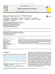
Figure 1. Outline (section) of an ATES System. The flow direction During the winter water is pumped from the warm well and cooled in a air convector, usually cold by the winter air. Then the cold water is injected into the cold well and if designed properly cold extraction balances the injected cold water. In the ATES system the cold is stored in both the groundwater and the grains of the aquifer. An ATES system requires relatively high hydraulic conductivity to reduce pumping energy and the required number of wells. The ATES system is used in maybe 25 countries all over the world. ATES is not a system to be used at any place, since it requires favourable geological conditions. Since the groundwater is often used as drinking water there is many times a conflict of interest in ground water use.
Figure 2. Existing ATES in Sweden 1999 (Olof Andersson).
Bo Nordell, Kjell Skogsberg, Cold Storage Applications WinterCities’2000, Energy and Environment, 14 February 2000, Luleå Sweden
3
Despite this type of problems there are many systems in countries with good aquifers. In the Netherlands there are almost 100 large-scale systems in operation and they expect an annual construction of forty more ATES during the next thirty years. Also in the most southern part of Sweden there are suitable aquifers that have been exploited for ATES. . The existing applications are concentrated around the Malmö region, Figure 2.
SEASONAL SNOW STORAGE FOR COOLING APPLICATIONS In many countries snow and ice have been stored from the winter for different cooling applications during the summer, usually for preserving of foodstuff. This was done already by the ancient Greeks who harvested ice from lakes and rivers, and stored it in barns under sawdust [13]. (MacCracken et.al. 1987). Snow and ice are renewables and seasonal storage of snow and ice in sawdust is now being rediscovered. These solid forms of water are unique in many ways. Its heat capacity of 4.18 kJ/kg (~1.2 Wh/kg); latent energy of melting 334 kJ/kg (~92.8 Wh/kg), and its melting point at 0oC makes it an excellent material for cold storage and comfort cooling applications. This storage capacity means that it requires 100 kWh to transform 1000 kg of ice at 0oC to water at 5oC. Any kind of snow or ice could be used, natural or artificially produced. In cities where heavy snowfall is common during the winter, snow is transported from streets and squares to a snow deposit. This snow is well packed but also contaminated. By having a controlled runoff it is possible to treat the melt water before it is let out. There is also the advantage of having the runoff smoothened out over a longer period [1]. The technique of seasonal snow storage was investigated in Ottawa, Canada, and the deposit was planned to store approximately 90,000 m3 of snow with a mean cooling load of 7000 kW. The snow should be protected with a reflective and insulating cover. They found that the best way to utilise the chill was to heat exchange melt water and re-circulate it to the snow storage. The estimated payback time was 10 years [11]. Another possibility to prevent the snow from melting is to put it under sawdust or wood-chips, as was done earlier. Sawdust seems to be an excellent thermal insulation and it is possible to keep most of a snow deposit from natural melting during the summer. After the cooling season the sawdust could be dried and used as bio-fuel in the heating plants of district heating. The explanations for the good qualities of sawdust as a thermal insulator are two. First it has a low thermal conductivity (varies with its humidity) and secondly it absorbs part of the melt water and increases the evaporation to the ambient air. When a liquid evaporates it cools the surface it evaporates from. This particular quality of sawdust will be studied in detail at Luleå University of Technology. The principle for utilising a snow deposit for seasonal storage of cold is shown in Figure 3. Snow is deposited on a watertight insulated paved surface. Leaning or vertical sides keeps the melt water under the snow. The cold water, at a constant temperature of 0oC, is pumped through a heat exchanger and then the heated melt water is re-circulated to the snow deposit. The returned warm water will be cooled on its passage through the snow and some snow will melt. This way the amount of melt water will increase and some water has to be discharged. This is done after the heat Bo Nordell, Kjell Skogsberg, Cold Storage Applications WinterCities’2000, Energy and Environment, 14 February 2000, Luleå Sweden
4
Sawdust or wood chips
Figure 3 Principle sketch of the snow storage of Sundsvall. The snow is contained under a layer of wood chips to prevent melting.1 Figure 4. The snow storage area at The Regional Hospital of Sundsvall, Sweden. The area is 140*60 m and the snow height will be about 3,5 m. “Pumphus” means pumping house. The hospital is to the right. exchanger. As long as there is snow in the storage the temperature of the melt water is 0oC, which means that the snow storage has no power limit in the extraction of cold. This is favourable considering the high power cost in DC previously mentioned.
THE SUNDSVALL SNOW STORAGE The Regional Hospital of Sundsvall in central Sweden requires 1000 MWh of cooling during the summer with a maximum cooling power of 1500 kW. Until now, conventional cooling machines have been used and instead of replacing the old cooling machines the hospital decided to meet the future (and increasing) cooling demand by utilising the city's snow deposit. They have an explicit goal to reduce the energy use by at least 50 % in new installations. The consulting engineering company VVB/VIAK AB and Luleå University of Technology designed the snow storage, located close to the hospital. The rectangular storage with a land area of 140 m x 60 m, Figure 4, contains 30,000 m3 (20,000 tons) of snow. This storage area was constructed to make it possible to double the snow storage volume in the future. A snow volume of 30,000 m3 contains theoretically 2000 MWh of “cold energy” that could be utilised for cooling. Because of natural melting of snow the amount of energy decreases with about 400-500 MWh (20-25 %). The Sundsvall snow storage system is outlined in Figure 5. The melt water at 0oC is pumped to a heat exchanger where the water of the hospital cooling system is cooled. Before the heat exchanger there are filters and an oil and gravel separator. After the heat exchanger the heated melt-water is re-circulated to the snow deposit by 36 individually adjustable pipes. Bo Nordell, Kjell Skogsberg, Cold Storage Applications WinterCities’2000, Energy and Environment, 14 February 2000, Luleå Sweden
5
Figure 5. Principle outline of water circulation of the snow storage at Sundsvall. The melt water is cleaned in three steps. The warm return water can be directed via 36 individually controlled outlets at the snow storage area.
Snow Melt The heat transfer at the interface between the surroundings and the snow governs snowmelt. There are several heat sources; from the groundwater, rain, sun, sky radiation and air. The most physically correct approach of modelling snowmelt is the energy budget but it is complicated to determine all parameters and processes for the complete energy budget. Therefore a simplified model where used where the heat transfer was divided into three parts; from ground water, from rain and from the surroundings, i.e. sun and warm air. The heat flow from ground water depends on the thermal properties of the material under the storage (asphalt, gravel, insulation, type of ground), depth to the groundwater surface, flow and temperature of groundwater. This problem can be considered 1D because of the large bottom area of the store. Then the maximum heat flow through the soil layer is given by Q=
λ ⋅ A ⋅ ΔT d
where Q is heat transfer [W] λ is heat conductivity of the ground [W/m*K] d is distance between groundwater surface and snow [m] A is bottom area of snow pile [m2] ΔT is temperature difference between storage and groundeater [K] To estimate the worst possible influence of groundwater, it was a assumed that a stong groundwater flow existed 1 m below ground surface (the groundwater level in Sundsvall is normally 0,65-2,5 m below the surface). The heat conductivity of the underlying ground is approximately 0,5 W/m,K. By assuming a storage temperature of 0oC and a groundwater temperature of 6oC the resulting heat flow is 3 W/m2. This means that the maximum heat flow through the bottom area of the store (8400 m2) becomes 25,2 kW, which results in a heat loss during the 5 months (3720 h) of about Bo Nordell, Kjell Skogsberg, Cold Storage Applications WinterCities’2000, Energy and Environment, 14 February 2000, Luleå Sweden
6
93,7 MWh. This corresponds to the melting of 1000 tons of snow, which is about 5 % of the total snow storage. Spontaneously people think that rain would cause a major snowmelt but this is not a fact. This is explained by the big latent heat of snow compared to the sensible heat for water. A rain of 8 mm at +10oC only melts one mm of snow. In the Sundsvall project a rough estimation is that half of the annual (750 mm) precipitation is rain under the cooling season, i.e. 375 mm. If the average rain temperature is +10oC this means that 47 mm of snow will melt, or about 260 tons, i.e. 1.1 %. The biggest melt is caused by the solar radiation and the convective heat transfer from warm air. A modified degree day model was used to simulate the snowmelt. It is the most common method for snowmelt modelling and gives satisfactory result [1], [3]. It was assumed that the initial shape remains throughout most of the melt period. A thermal insulation (wood chips) thickness of 0.2 m was assumed with a thermal conductivity of 0.35 W/m,K [6].The snowmelt caused by heat transfer from the air through the wood chip layer was calculated by the model to 4000 ton, i.e. 20 % of the total snow storage. The natural snowmelt period starts 25th February in the Sundsvall region. Normally, without thermal insulation, the 30,000 m3 snow deposit would last until mid June. With 0.2 m of wood chips and no cold extraction the snow will last until the next winter. With a cold extraction of 1000 MWh most of the snow will melt during the summer. To summarise the snowmelt calculations 5260 tons of snow will melt during the as a result of the warm summer days and the groundwater flow under the storage areas. The remaining snow has a latent cold content of 1350 MWh, which will be used to cover the estimated cold demand of the hospital (1000 MWh).
Photo of the Sundsvall Snow Storage, November 1999.
Bo Nordell, Kjell Skogsberg, Cold Storage Applications WinterCities’2000, Energy and Environment, 14 February 2000, Luleå Sweden
7
The construction work of the Sundsvall snow storage was completed in November 1999 and the winter 1999/2000 will be the first of its operation. During the summer of 2000 the first extraction of cold will take place. LTU is monitoring and evaluating the 100000,0
75000,0
50000,0
25000,0
27-sep
16-sep
05-sep
25-aug
14-aug
03-aug
23-jul
12-jul
01-jul
20-jun
09-jun
29-maj
18-maj
07-maj
26-apr
15-apr
0,0
Figure 6. Starting with 100,000 m3 in mid April graph shows natural snowmelt (top curve) and accumulated snowmelt also including snowmelt operation of the store. We expect to gain new ideas of how to improve this technology further. This evaluation is part of a PhD work with the objectives to write a manual on how to design, construct and operate snow storage systems. THE ASSI SNOW STORAGE ASSI Kraftliner is a big company that owns paper mill in Piteå, a town located 50 km south of Luleå. This paper mill, which annually produces 650,000 tons of paper, has a continuos cooling demand of 1500 kW over the year. During the winter season, cold water from the nearby Pite River is used. During this period, when ice covered, the water temperature is close to 0oC. During the summer the water temperature is too high for cooling and as a consequence absorption coolers are used during five months of the summer season. LTU made recently a prestudy to investigate if a snow storage would solve the cooling problem at the ASSI plant. It seems like ASSI has excellent conditions for snow storage. First of all no reconstruction has to be made at the factory since the melted water of the snow storage would be similar to the cold winter water of the Pite River. They also have big areas available for the storage system. On top of that the snow deposit of the city (60,000 m3) is located close to the ASSI plant. There is also snow available at the surrounding land area of the paper mill. So, the fundamentals for the snow storage was good already form the start. The task of the ASSI snow storage was to replace the cooling machines i.e. to deliver 5000 MWh during May to September. This means a mean power of 1500 kW of cooling with peak loads of 3000 kW. Performed simulations showed that 100,000 m3 of snow would be sufficient to cover the required cooling demand. Figure 6 shows the natural melt (top curve) and the total snowmelt as a result of both natural melt and cold extraction. The shape of the snow storage was assumed as a cut cone with a diameter of 142 m and an initial height of 7 m, which means a snow storage area of 15800 m2. The snow Bo Nordell, Kjell Skogsberg, Cold Storage Applications WinterCities’2000, Energy and Environment, 14 February 2000, Luleå Sweden
8
storage was thermally insulated by 0.2 m of sawdust. The initial snow volume of 100,000 m3 would be reduced by 19,000 m3 from natural melting. The total cooling capacity of the store would be 5500 MWh of which 4900 MWh is latent energy and 600 MWh is sensible energy. The mean extraction power was 1528 kW. The water flow rate form the store to ASSI would be 132 m3/h (max 264) for an estimated temperature difference of 10oC. The natural melt would cause a melt water flow of 420 m3/day. The total constuction cost was estimated to 8 MSEK (1MUSD). As a result of this prestudy ASSI decided to continue with detailed design and cost calculations. Final remarks The snow storage has a great potential. It is an example of a natural technology where local resources are utilised to save prime energy. It is a remarkably simple and obvious technology. There is no limit in extraction power.
Acknowledgements This study is part of Kjell Skogsberg's PhD studies and was funded by Energimyndigheten. References [1]
Sundin, E. 1998. An Approach to Using the Degree Day Method for Urban Snow Deposit Melt. Vatten, 54: 123-130.
[2]
Sundin, E. 1998. Snow Deposit Melt and Atmospheric Icing Analysis and Modelling by Weather Station Data. Doctoral Thesis 1998:37. Division of Water Resources Engineering. Luleå University of Technology.
[3]
WMO 1986. Intercomparison of Models of Snowmelt Runoff. World Meteorological Organization No. 646 Operational Hydrology Report No. 23, 36p. +17 Annexes.
[4]
Viklander, M. 1994. Melting of Urban Snow Deposits – A Water Quality Study. Licentiate Thesis 1994:19L. Division of Sanitary Engineering. Luleå University of Technology.
[5]
Sundin, E., Andreasson, P., and Viklander, M. 1998. An Energy Budget Approach to Urban Snow Deposit Melt. Nordic Hydrology, (30), pp. 39-56.
[6]
Tefyma el dyl
[7]
Abdelnour, R., Labrecque, B. and Underdown, A. Technoeconomic analysis of three seasonal cooling technologies; ice block, frozen pond and waste snow pit (1994). Calorstock ´94, Conference on thermal energy storage.
[8]
Buies, S. Engineering of a life-size fabrikaglace (1985). Centre de Recherche du Quebec (CRIQ), Technical report no. FAB-85-051. Bo Nordell, Kjell Skogsberg, Cold Storage Applications WinterCities’2000, Energy and Environment, 14 February 2000, Luleå Sweden
9
[9]
Kobiyama, M. Himuro type storage shed using the ice stored in winter season (1987). International symposium on cold regions heat transfer 1987, proceedings, s 167-170.
[10] Morofsky, E. L. Developing and introducing an innovative building cooling technology: Strategy formulation based on market and technology considerations (1984). Issues in strategic management, Adm 6395. [11] Morofsky, E. L. Long-term latent energy storage- the Canadian perspective (1982). US China conference on energy, resources and environment. [12] Okajima, K., Nakagawa, H., Matsuda, S. and Yamasita, T. (1997). A cold storage for food using only natural energy. Snow Engineering, p. 569-572. ISBN 90 5410865 7 [13] Taylor, T. B. Ice ponds (1985). AIP Conference Proceedings 1985, s 562-575.
Bo Nordell, Kjell Skogsberg, Cold Storage Applications WinterCities’2000, Energy and Environment, 14 February 2000, Luleå Sweden
10