Collaborative Covert Communication Design Based on Lattice
Recommend Documents
initial d esign v ision an d m ission. Th is paper ad dresses a fram ework of m anaging communication-based collaborative design processes focused on close ...
The Military Technical College,. Cairo, Egypt 11331. ABSTRACT. This paper presents a steganographic model which utilizes cover video files to conceal the ...
Aug 23, 2016 - secretly delivering a message was to hide the fact that a message was even delivered at ...... Hide and seek: An introduction to steganography.
to pay more attention to a large number of issues that had arisen in data hiding ... If the transmission is rather continuous in time, one may refer to the technique as a covert ... using a DNA vector and restriction enzymes. The ... Cut the vector w
technology involved is often novel and unfamiliar to the team. ... the study of automotive development projects by Clark and Fujimoto (1991). .... years of age and many had at least a diploma (39%) or an undergraduate university degree (29%).
Abstractâ In a digital communications systems where the data transferred in bit stream, the processing ..... [3] S. S. Haykin, Communication Systems, 3rd ed.
Our research is focused on problem solving communication in design projects .... Page 7 ... themselves about their work related problems very effectively, since they .... the standardized scores in a team to create a team measure, or (c) average.
Abstract. In this paper, a novel design of third and fifth order differentiator based on lattice wave digital filter. (LWDF), established on optimizing L1-error ...
Jun 15, 2015 - lack of a QTL mapping method based on lattice design dictates that .... is an nÃ1 vector of 1s, XR is an nÃr design matrix whose i-th column is ...
Sep 30, 2014 - Not only I learned a lot about cryptography, but I also got to discover .... I Design and Implementation of a Lattice-Based Signature Scheme. 29.
shifting arrangements, digital signatures, and covert ... to the enormous use of computers and digital media, ... This procedure can be explained as follows:.
Abbas Cheddad, Joan Condell, Kevin Curran, Paul Mc Kevitt, âDigital Image Steganography: Survey and Analysis of Current Methodsâ, Elsevier, Signal ...
called Collaborative Learning Flow Patterns (CLFPs), represent best practices that are repetitively .... The tool is called Collage: COLaborative LeArning desiGn Editor. ..... It mainly provides a shared web-based workspace in which documents.
replacing the bar codes as RFID tags provide some excellent facilities such as location tracking by which ... Covert Channel communication in Computer Network has been a topic ... remote keyless entry for automobiles, etc [2], [3]. But due to its ...
Apr 17, 2017 - (i.e., hiding the wireless transmission) is desired in many application scenarios of ...... Cambridge, UK: Cambridge. University Press, 2011.
called Collaborative Learning Flow Patterns (CLFPs), represent best practices that are ..... Determine how computer support is best used to sustain learning and ...
Aug 14, 2016 - the Chinese government has proposed the âMade in China. 2025â strategic framework, in which enterprises are seen not only as players in the ..... From the data for the five manual design tasks corre- sponding to the Lekin ...
Online learning is now a reality thanks to the development of Internet and to the virtual environments commonly called LMS (Learning Management System).
Jul 29, 2014 - asynchronous: no messages are directly exchanged between the sender and ..... ecosystem can be found on websites like The Pirate Bay. The.
Sep 20, 2017 - to detect that the communication is happening at all. ... the authors assumed that Eve's detectors have larger dark counts than Bob's and she ...
Jul 29, 2014 - 3http://torrentfreak.com/bittorrent-surges-to-150-million-monthly-users-120109/ . ecosystem can be found on websites like The Pirate Bay. The.
AbstractâBotnets are continuously evolving to evade detection. Current botnet detection systems are designed to be positioned on the edges of a private ...
Jul 17, 2018 - characteristics of the two, the physical layer security model based on .... the location of the destination node, and the CJ strategy is more ...
concurrent sub-space optimization [3,4], collaborative optimization ... Sections 2 and 3 demonstrate how this dynamic ..... [6] Sobieszczanski-Sobieski, J. and S. Kodiyalam, 2001, .... Computational Aerodynamicsâ, John Wiley & Sons, New. York.
Collaborative Covert Communication Design Based on Lattice
Jun 28, 2017 - Lattice Reduction Aided Multiple User Detection Method. Baoguo Yu ..... B by an elementary column transfer from the base vectors of the lattice ...
Hindawi Wireless Communications and Mobile Computing Volume 2017, Article ID 8949430, 8 pages https://doi.org/10.1155/2017/8949430
Research Article Collaborative Covert Communication Design Based on Lattice Reduction Aided Multiple User Detection Method Baoguo Yu,1,2 Yachuan Bao,1,2 Haitao Wei,1,2 Xin Huang,3 and Yuquan Shu1,2 1
State Key Laboratory of Satellite Navigation System and Equipment Technology, Shijiazhuang, China The 54th Research Institute of CETC, Shijiazhuang, China 3 Northwestern Polytechnical University, Xi’an, China 2
1. Introduction For the purposes of information transmission security, covert communication is applied in many special scenarios, including military and national security applications. The development of covert communication systems shows a trend for diversity, where different designs are tailored to different applications. Covert communication systems can be divided into two main groups: covert information transmission and covert signal transmission. The covert transmission of information can be satisfied by securing both the information source and the communication protocol encryption. A typical schema includes information transmission with image and video compression [1] and covert P2P channels over the Internet [2], among others. The covert transmission of signals is realized by signal or transmitter-receiver mode design with low detectability. Typical schemes include designs based on direct antenna modulation (DAM) [3] and spread spectrum (SS) communication. The most common method for covert communication design based on SS involves reducing the signal power to
hide it in noise or transmit the covert signal covered by several high-power signals. An improved method involving frequency and code hopping is proposed in this paper, with an improvement in anticapture performance [4]. SS signals are also designed to transmit coupled with satellite television signals and broadcast signals to achieve covert communication [5]. Transmitting low-power covert signals coupled with high-power signals is an effective way to reduce the detectability of a signal. However, the design will be restricted by multiple access interference (MAI) and wireless link resources. To achieve high imperceptibility, signal power and information rates will be limited. Research on covert communication based on SS is discussed in this paper. Lattice reduction (LR) is applied to multiple user detection (MUD) of SS communication, and an LR-MUD algorithm is also proposed. Near maximum likelihood (ML) performance of lower power signals is achieved with low complexity in serious MAI scenarios. Based on the LR-MUD algorithm, a novel design of collaborative SS covert communication is proposed. Covert signals
2
Wireless Communications and Mobile Computing
can be transmitted with the coverage of a greater number of high-power signals. Thus, the transmission concealment and robustness of covert communication will be improved significantly. The remainder of the paper is organized as follows: Section 2 gives the covert communication model based on SS communication, while the traditional MUD method is analyzed in Section 3. The lattice theory and lattice aided MUD algorithm is given in Section 4, followed by simulation experiments of the algorithm in Section 5. The design of a system based on LR-MUD is given in Section 6. Finally, the conclusions are provided in Section 7.
2. Covert Communication Model Based on Spread Spectrum Consider a covert SS communication system consisting of one low-power covert signal and 𝑁 − 1 high-power signals. The received signal at the receiver is 𝑁
𝑟 (𝑡) = ∑ 𝐴 𝑘 (𝑡) 𝑏𝑘 (𝑡) PN𝑘 (𝑡) + 𝑛 (𝑡) ,
(1)
𝑘=1
where 𝐴 is the signal amplitude, 𝑏 is the information bit which takes values in the interval {−1, +1}, and PN is the pseudo noise code used for spread spectrum modulation. Suppose signal 𝑘 is the desired signal. Then, the output of the matched filter for signal 𝑘 is as follows: 𝑇𝑏
𝑦𝑘 = ∫ 𝑟 (𝑡) PN𝑘 (𝑡) 𝑑𝑡 0
𝑁
𝑇𝑏
= ∫ [ ∑ 𝐴 𝑘 𝑏𝑘 PN𝑘 (𝑡) + 𝑛 (𝑡)] PN𝑘 (𝑡) 𝑑𝑡 0
𝑘=1
(2)
𝑁
= 𝐴 𝑘 𝑏𝑘 + ∑ 𝐴 𝑗 𝑏𝑗 𝜌𝑗𝑘 + 𝑛𝑘 , 𝑗=1,𝑗=𝑘 ̸
𝑇𝑏
𝑇
where 𝜌𝑗𝑘 = ∫0 PN𝑘 (𝑡)PN𝑗 (𝑡)𝑑𝑡, 𝑛𝑘 = ∫0 𝑏 𝑛(𝑡)PN𝑘 (𝑡)𝑑𝑡, and 𝑇𝑏 is the time length of the information bit. The first item is the expected signal, whereas the second item is the correlation sum of the spread spectrum code and other signals, which is the MAI. The third item is the channel noise. The output of a matched filter of 𝑁 signals is given below: 𝑇
Definite H = RA and formula (3) can be written as follows: Y = Hb + n.
(4)
In traditional detection, the output of a matched filter will be sampled at every bit interval, and the bit will be decided on the basis of the decision threshold: ̂ = dec (Y) = dec (Hb + n) , b
(5)
where dec( ) represents the decision value of the bit. Getting the bit directly with the decision of the matched filer output, critical errors could possibly be caused by MAI, especially for the covert low-power signal.
3. Multiple User Detection Method for Spread Spectrum Communication As an effective method to improve the capacity of a spread spectrum communication system, a MAI suppression method has been developed in depth [6, 7]. The typical method includes two types: multiple user detection (MUD) and an interference cancellation method. The foundation of the MUD method is the calculation of correlation between signals, and the interference is suppressed by the decorrelation process. The traditional MUD method includes the zero forcing (ZF) method and the minimum mean square error (MMSE) method, among many other new methods proposed over the years. Here, a MUD method aided by a Hopfield neural network is proposed [8]. With the method, detection performance can be improved, but the improvement will decrease with an increase in signal number. A weighted orthogonal matched filter method based on quantum signal processing is proposed [9]. With this method, the estimation of noise power is not necessary, but the detection performance is reduced compared to the MMSE method. A blind MUD method based on Schmidt-orthogonalization and subspace-tracking Kalman filtering is also presented, and with this method, the complexity of the blind MUD method is reduced [10]. There are two types of interference cancellation methods: serial interference cancellation (SIC) and parallel interference cancellation (PIC). Based on the correlation computation of signals, the signal interference influence of other signals can be cancelled by the serial or parallel mode. The performance of this kind of method is suboptimal compared with the MUD method. Its performance is limited by the initial detection accuracy of multiple signals. When multiple interference is serious, the platform effect will emerge early and the detection performance will not be ideal [11, 12]. In practical applications, the detection performance can be improved with usage combined with high-gain error correction coding. The benefit from the low computation complexity and flexible processing architecture leads to this interference cancellation method being applied in some satellite communication system designs. The article is focused on the MUD method. The basic idea of the MUD method is to cancel MAI between signals with
Wireless Communications and Mobile Computing
3
the calculation and transformation of a correlation matrix. Maximum likelihood (ML), ZF, and MMSE methods are typical algorithms applied. The ML algorithm is the theoretical optimum MUD algorithm. Its principle is shown as follows. Generate a transmit signal traversal set and complete the following operation: ̂ = argmin (Y − Hb) b
b ∈ {b} .
(6)
The main process of ZF algorithm involves calculating the inverse matrix G of the correlation matrix H and then calculating the dot product of G and the output of the matched filter group. After that, estimation of transmitter signals can be obtained with the following decision [13]: 𝐻
−1
𝐻
G = (H H) H ,
(7)
̂ = dec (G (Hb + n)) = b + n . b
n is the noise component after ZF conversion and bit decision. The calculation complexity of the ZF method is relatively low and scales with the number of signals. The estimation error covariance matrix is as follows: 𝐻
−1
̂ − b) (b ̂ − b) } = 𝜎2 (H𝐻H) . 𝜑MMSE = 𝐸 {(b
(8)
𝜎2 is the variance of noise. The influence of noise is always increased with the ZF method, which is why ZF performs poorly with a low signal noise ratio (SNR) scenario. (H𝐻H)−1 can be defined as the demodulation error coefficient for ZF, which measures how the influence of noise is enlarged by the ZF method. The basic idea of MMSE is to minimize the mean square error between transmit signal and estimation result. Unlike the ZF method, MMSE takes noise suppression into account, and thus the estimation performance is improved to some extent. The process of MMSE is as follows: −1
G = (H𝐻H + 𝜎2 I) H𝐻, ̂ = dec (G (Hb + n)) = b + n . b
(9)
n is the noise component after MMSE conversion and bit decision. The estimation error covariance matrix of MMSE is ̂ − b) (b ̂ − b)𝐻} 𝜑MMSE = 𝐸 {(b −1
(10)
= 𝜎2 (H𝐻H + 𝜎2 I) . Based on formal analysis, it can be shown that the performance of MUD is influenced by noise and the orthogonality of the correlation matrix. If the correlation matrix is orthogonal, the detection performance of MUD will equal that of the performance of a single signal without MAI. In addition, for special users, it is possible to suppress noise with the transformation of the correlation matrix. Searching for a method, which can improve the orthogonality of the matrix, is an important pathway to fulfill enhanced MAI cancellation.
Square lattice
B={
Rhombic lattice
1 0 0 1
}
B=
Hexagon lattice
1 1 2 { } 2 0 1
B=
1 2 1 } { 2 0 3
Figure 1: Several typical lattices.
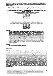
4. Multiple User Detection Methods Based on Lattice Reduction 4.1. Lattice Theory. A lattice is a congregation of scatter points arranged with scheduled rule [14–16]. Any lattice can be generated by a group of linear unrelated vectors. Figure 1 shows several typical types of lattice. Suppose a group of 𝑛 dimensional vectors is defined by B = (b1 , b2 , . . . , b𝑚 ) ∈ 𝑅𝑛 . The number of vectors is 𝑚 and the vectors are linearly independent. The integrated linear combination of the vectors can form an 𝑚-dimensional lattice. It can be written as follows: 𝑚
𝐿 (b1 , b2 , . . . , b𝑚 ) = ∑𝑡𝑖 𝑏𝑖 , 𝑡𝑖 ∈ 𝑍.
(11)
𝑖=1
Vector B = (b1 , b2 , . . . , b𝑚 ) is one foundation of the lattice, and t = [𝑡1 , 𝑡2 , . . . , 𝑡𝑛 ]𝑇 is the coefficient vector composed of integers. It can be written in matrix mode: 𝐿 = {l = Bt} .
(12)
The three different lattices are generated from the basis below the figures. The dimensionality is decided by the number of base vectors. The dimensionality of the base vector is called the rank of the generated lattice. The basis of a lattice is diversified. A lattice can be denoted by different bases. An 𝑚-dimensional space can be generated by any group of 𝑚 linearly independent vectors, but not any group of 𝑚 linearly independent vectors can form a lattice. There is a fixed relation between the different base vectors of one lattice. For the lattice 𝐿(B) generated by vector group B = (b1 , b2 , . . . , b𝑚 ), all of the vectors transformed from B by an elementary column transfer from the base vectors of the lattice. The product of several elementary column transfer matrices equals one unimodular transfer matrix T. The elements of T are complex integers and the determinant of T equals ±1. As long as T is a unimodular matrix, the same lattice can be generated by B and BT. 𝐿 (B) = 𝐿 (BT) .
(13)
The shortest base vector, that is, the base vector of shortest length, is a common research object for a lattice. If the shortest base vector cannot be reached, the nearest short base vector is always desired. The basis of a lattice has the
4
Wireless Communications and Mobile Computing
Input: Q, R Reduction process: Initialization: Q = Q, R = R, 𝑘 = 2; While 𝑘 ≤ 𝑛 for 𝑙 = 𝑘 − 1, . . . , 1 𝑏 = R (𝑙, 𝑘)/R (𝑙, 𝑙), 𝑏 rounded to complex integer 𝜇 if (𝜇 ≠ 0) R (1 : 𝑙, 𝑘) = R (1 : 𝑙, 𝑘) − 𝜇R (1 : 𝑙, 𝑙) P(:, 𝑘) = P(:, 𝑘) − 𝜇P(:, 𝑙) end end if (𝛿‖R (𝑘 − 1, 𝑘 − 1)‖2 > ‖R (𝑘, 𝑘)‖2 + ‖R (𝑘 − 1, 𝑘)‖2 ) Interchange column 𝑘 − 1 and column 𝑘 of matrix R and P. Calculate the Givens rotation matrix 𝜃, to make R (𝑘, 𝑘 − 1) = 0: R (𝑘 − 1 : 𝑘, 𝑘 − 1 : 𝑁𝑡 ) = 𝜃R (𝑘 − 1 : 𝑘, 𝑘 − 1 : 𝑁𝑡 ) Q (:, 𝑘 − 1 : 𝑘) = Q (:, 𝑘 − 1 : 𝑘) 𝜃𝐻 c s R (𝑘, 𝑘 − 1) R (𝑘 − 1, 𝑘 − 1) , s= ) (𝜃 = [ ], c = ‖R (𝑘 − 1 : 𝑘, 𝑘 − 1)‖ ‖R (𝑘 − 1 : 𝑘, 𝑘 − 1)‖ −s c 𝑘 = max {𝑘 − 1, 2} else 𝑘=𝑘+1 end If 𝑘 > 𝑛, export R Q and transfer matrix P Reduction completed. Algorithm 1: Algorithm LLL.
feature that a shorter basis will be more orthometric. Lattice reduction is the process by which the nearest short base vector is found while the orthogonality of the base vector is improved. 4.2. Lattice Reduction Algorithms. Lattice reduction is a process to obtain the nearest short base vector while the orthogonality of the base vector is improved. Common lattice reduction algorithms include the Lenstra–Lenstra–Lov´asz (LLL) reduction [17] and the Seysen reduction [18, 19]. To measure the orthogonality of a lattice basis, the degree of orthogonality defect is defined. Suppose (b1 , b2 , . . . , b𝑚 ) is one group of base vectors of lattice L, and the base vector matrix is H. The degree of orthogonality defect of H is defined as Δ (H) =
Then, H is the matrix processed by LLL reduction. The basic procedure of LLL [20–22] is shown in Algorithm 1 Compared with the LLL reduction, the main difference in the Seysen reduction is a different definition of the degree of orthogonality defect: 𝑀 2 2 𝑆 (H) = ∑ h𝑚 h#𝑚 .
(17)
𝑚=1
(14)
In the formula, 𝑀 is the column number of H, h𝑚 is the column 𝑚 of H, and det( ) is the determinant operator. Δ(H) ≥ 1, and only when H is an orthogonal matrix, Δ(H) = 1. Suppose H is the matrix generated by an LLL reduction: H = HP, P is a unimodular matrix.
If R is found via a QR decomposition of H , it satisfies the following two conditions:
(15)
In the formula, H has 𝑀 columns. h𝑚 is the 𝑚 column of H, and h#𝑚 is the 𝑚 column of the dual matrix H# = ((H𝐻H)−1 H𝐻)𝐻 [12, 13]. When H is an orthogonal matrix, 𝑆 (H)min = 𝑀.
(18)
The Seysen algorithm takes both the raw matrix and dual matrix into account; as a result, a better reduction performance can be achieved.
Wireless Communications and Mobile Computing
5
1: Estimation of signals Y is calculated by matched filters. Signal power, relative delay, and carrier phase difference of signals are estimated. 2: A correlation matrix between signals H is calculated. 3: Process H with lattice reduction algorithm (LLL or Seysen). Conversion matrix P and optimized matrix H = HP is obtained. 4: The ZF or MMSE method is implemented ̃ LLL_ZF = (H𝐻 H )−1 H𝐻 Y Z ̃ LLL_MMSE = (H𝐻 H + 𝜎2 P𝐻 P)−1 H𝐻 Y Z 5: The modified quantization in improved lattice space is taken: ̂ = 𝑎 (⌈ 1 Z− ̃ 1 P−1 I⌋ + 1 P−1 I) . Z 𝑎 2 2 𝑎 is the power normalization parameter, and ⌈ ⌋ is the roundness of real value. ̂ is calculated. 6: Final detection result X ̂ = PZ ̂ X Algorithm 2: Algorithm LR-MUD.
Matched filter
Correlation matrix calculation
Lattice reduction
MUD
100
Modified quantization
Figure 2: Process of the LR-MUD algorithm. BER
10−1
4.3. Lattice Reduction Aided Multiple User Detection (LRMUD). With lattice reduction, the correlation matrix H can be transformed to matrix H , which has better orthogonality. The analysis of the MUD method in Section 2 shows that with a correlation matrix with better orthogonality the influence of noise can be better suppressed. The process of lattice reduction aided multiple user detection algorithm is shown in Algorithm 2 The basic process of the algorithm is shown in Figure 2. The signal power and signal delay estimation accuracy is important to the performance of the algorithm. To estimate the signal power in the MAI scene, a synchronization-head can be used to improve the estimation accuracy. The signal delay and carrier phase information can be given by the signal tracking loop. The measurement accuracy can be improved by extending integration time and by using a large correlator design. Related research shows that week spread spectrum signals like GPS can be tracked stably when SNR is lower than −4 dB. The complexity of ML is 𝑂(𝑁𝑠 𝑀), where 𝑁𝑠 is the modulation order and 𝑀 is the signal number. The complexity of ML increases with 𝑁𝑠 exponentially. The complexity of ZF and MMSE is relatively low, given as 𝑂(𝑀3 ). The main computation of the MUD method is in the inversion of the correlation matrix. The lattice reduction process is added based on the MUD in the LR-MUD method. The increased computation includes QR decomposition and inversion of matrix P. The increase in complexity is linear, and thus the complexity is still 𝑂(𝑀3 ). Compared with ML, LR-MUD has superior performance in regard to complexity.
10−2
10−3 −6
−4
−2
0 SNR (dB)
Matched filter ZF ZF-LLL ZF-Seysen
2
4
6
MMSE MMSE-LLL MMSE-Seysen ML
Figure 3: BER of LR-MUD with different SNR scenarios.
5. Simulation and Analysis In this section, simulations of the LR-MUD method of SS communication are presented. The signal modulation is QPSK, and the spread code sequence is a group of gold codes. Figure 3 shows a demodulation BER in different SNR scenarios. The signal number is 6, and the spread ratio is 16. Signal power is distributed randomly in the range of 0–6 dB, and the BER of all signals is counted. MAI can be cancelled effectively by the ZF or MMSE method. The BER of the two algorithms is lower than the BER of the basic matched filter method, but the performance is much weaker than that of the ML method. In the figure, ZF-LLL and ZF-Seysen are the tested LR-MUD methods based on a combination of the ZF method using a lattice reduction by LLL and Seysen. Likewise, MMSE-LLL and MMSE-Seysen are the tested LR-MUD methods based on the MMSE method using a lattice reduction by LLL and Seysen. The BER of LR-MUD is
6
Wireless Communications and Mobile Computing 100
100 10−1
10−1 BER
BER
10−2
10−2
10−3 10−4 10−5
10−3
2
3
4
Matched filter ZF ZF-LLL ZF-Seysen
5 6 Signal number
7
8
MMSE MMSE-LLL MMSE-Seysen ML
2
3
4
5 6 Signal number
7
Degree of orthogonality defect
0
2
4 6 8 10 12 14 16 18 Interference to desired signal power ratio (dB)
Matched filter ZF ZF-LLL ZF-Seysen
Figure 4: BER of desired signal with different signal numbers. 100 90 80 70 60 50 40 30 20 10 0
10−6
8
Matrix processed by lattice reduction Initial correlation matrix
Figure 5: Degree of orthogonality defect of a correlation matrix with different signal numbers.
reduced significantly compared with the MUD methods, and its performance approaches ML with an increase of SNR. The algorithm gain compared to MUD is more than 4 dB. Figure 4 shows the demodulation BER of a desired signal with different numbers of interference signals. Here, the spread ratio is 16 and the SNR of the covert signal is 0 dB. The power of the other signals is randomly distributed in the 0–20 dB range compared to the desired signal. The BER of the traditional MUD method increases with an increase in signal number. Performance near ML is achieved by LR-MUD and remains steady even with an increase in signal number. LRMUD shows superiority when subjected to a greater number of interference signals. With the same BER requirements, the number of interfering high-power signals is 7 for LR-MUD, compared to 2 for the traditional MUD method. Figure 5 shows the variation in the orthogonality of the correlation matrix. Along with the increase of signal number, the degree of orthogonality defect for the initial correlation matrix increases, which results in the demodulation deterioration in the traditional MUD method. In contrast, the
20
MMSE MMSE-LLL MMSE-Seysen ML
Figure 6: BER of a desired signal with different interference to signal power ratios.
degree of orthogonality defect of the matrix processed by LR increases only slightly. Furthermore, this is the explanation for why LR-MUD performs better than the traditional MUD method. Figure 6 shows the simulation result with different signal power ratios. The spread ratio is 32 and the signal number is 6. SNR of covert signal is 0 dB. The power of the covert signal and noise remain stable, while the power of 5 interference signals increases gradually. The BER of the desired signal is counted. The BER of the MUD method does not change with the increase in power; a fixed gap remains between ML and MUD method. The BER of LR-MUD decreases with the power increase of interference signals, and finally near ML performance is achieved when the interference to signal power ratio is larger than 10 dB. This shows the effect of lattice reduction. When the correlation between signals is good, the algorithm gain of the LR is relatively limited. When the correlation between signals is poor, the algorithm gain of LR will increase. Therefore, LR-MUD is suitable to use in intense near-far scenarios. Figure 7 shows the variation of the degree of orthogonality defect for a correlation matrix with an increase of interference to signal power ratio. The orthogonality defect of the correlation matrix does not change. With a lattice reduction, the orthogonality of the correlation matrix is improved, and the effect improves further with an increase in interference power. Figure 8 shows the variation of demodulation error coefficient for a desired signal with an increase of interference to signal power ratio. The change of the demodulation error coefficient is consistent with the BER change shown in Figure 6. With additional increase of interference to signal power ratio, the amplification of noise decreases with the LR-MUD method. This is the main reason why LR-MUD performs better than traditional the MUD method.
Degree of orthogonality defect
Wireless Communications and Mobile Computing 11 10 9 8 7 6 5 4 3 2 1
7 SS signal transmitter .. . Covert transmitter .. . SS signal transmitter
0
2
4 6 8 10 12 14 16 18 Interference to desired signal power ratio (dB)
20
Highpower signal covert signal
LR-MUD
Estimation of covert signal
High-power signal Covert signal receiver
100
Figure 7: The degree of orthogonality defect for a correlation matrix with different interference to signal power ratios.
10−1 BER
×10−3 2
10−2 10−3
1.8 1.6
10−4 12
14
16
1.4 1.2
18
20 22 Spread ratio
Matched filter ZF ZF-LLL ZF-Seysen
1 0.8
Signal capture and track
Figure 9: System diagram of a covert communications system based on LR-MUD.
Initial correlation matrix Matrix processed by lattice reduction
Demodulation error coefficient
High-power signal
0
2
4 6 8 10 12 14 16 18 Interference to desired signal power ratio (dB)
20
LR-MUD ZF
Figure 8: Demodulation error coefficient with different interference to signal power ratios.
6. Design of a Covert Communications System Based on LR-MUD Because of the excellent performance gain in intense nearfar scenarios, LR-MUD is appropriate for implementation in covert communication systems based on SS principles. A block diagram for a covert communications system design is given in Figure 9. The system includes a covert signal transmitter, covert signal receiver, and common signal transmitter. High-power signals can be transmitted by the covert transmitter as well as a number of common signal transmitters. The covert signal and at least one high-power signal should be transmitted by a covert transmitter synchronously. At the receiver, the capture and tracking of covert signals should be performed using the synchronous high-power signal. All signals will be demodulated with the LR-MUD method. Figure 10 is the simulation result of the covert transmission performance with different spread ratios. SNR of covert signal is 0 dB and coverage signal number is 5. With
24
26
28
MMSE MMSE-LLL MMSE-Seysen ML
Figure 10: BER of a covert signal with different spread ratios.
the increase of spread ratio, BER decreases with the cost of information rate. The same BER can be achieved by LR-MUD with a lower spread ratio compared to the common MUD method. Higher information rates can be realized by LRMUD with the same wireless link resource and concealment requirements.
7. Summary and Conclusions In this paper, lattice reduction theory and related algorithms are applied to the MUD of a spread spectrum communications system, and an algorithm called LR-MUD is presented. Theoretical analyses and simulation results on the LR-MUD method are carried out, showing excellent nearfar effect suppression performance. Based on the LR-MUD method, a design of a covert communications system can be feasibly realized. The covert signal can be transmitted at a higher information rate with the coverage of more highpower cochannel signals. Thus, higher transmission rates and concealment performance are achieved using the same link resources.
Conflicts of Interest The authors declare that they have no conflicts of interest.
8
Acknowledgments The authors acknowledge the National Natural Science Foundation of China (Grant 91638203) and the National Key Research and Development Program of China (Grant 2016YFB0502102).
References [1] Y. Cao, H. Zhang, X. Zhao, and H. Yu, “Covert communication by compressed videos exploiting the uncertainty of motion estimation,” IEEE Communications Letters, vol. 19, no. 2, pp. 203–206, 2015. [2] M. Cunche, M.-A. Kaafar, and R. Boreli, “Asynchronous covert communication using bittorrent trackers,” in Proceedings of the 16th IEEE International Conference on High Performance Computing and Communications, HPCC 2014, 11th IEEE International Conference on Embedded Software and Systems, ICESS 2014 and 6th International Symposium on Cyberspace Safety and Security, CSS 2014, pp. 827–830, fra, August 2014. [3] H. Shi and A. Tennant, “Covert communication using a directly modulated array transmitter,” in Proceedings of the 8th European Conference on Antennas and Propagation, EuCAP 2014, pp. 352– 354, nld, April 2014. [4] L. Li, J. Zheng, and L. Zheng, “The Chaotic Code-hopping Spread Spectrum Communication System[J],” Science Technology and Engineering, vol. 13, no. 30, pp. 176–180, 2014. [5] X. Zhao, X. Ma, and W. Qu, “Analysis of the parasitic small signal coupling with RDSS RF signal [J],” Telecommunication Engineering, vol. 49, no. 8, pp. 40–44, 2009. [6] Y. Hou, M. Li, X. Yuan, Y. T. Hou, and W. Lou, “Cooperative Interference Mitigation for Heterogeneous Multi-Hop Wireless Networks Coexistence,” IEEE Transactions on Wireless Communications, vol. 15, no. 8, pp. 5328–5340, 2016. [7] Q. Zhou and X. Ma, “Receiver designs for differential UWB systems with multiple access interference,” IEEE Transactions on Communications, vol. 62, no. 1, pp. 126–134, 2014. [8] G. I. Kechriotis and E. S. Manolakos, “Hopfield neural network implementation of the optimal CDMA multiuser detector,” IEEE Transactions on Neural Networks, vol. 7, no. 1, pp. 131–141, 1996. [9] S.-N. Shi, Y. Shang, and Q.-L. Liang, “A novel linear multi-user detector,” Acta Electronica Sinica, vol. 35, no. 3, pp. 426–429, 2007. [10] Y. Yu, J. Li, Z. Wang, S. Wang, and H. Zhang, “Blind multiuser detection in MC-CDMA: Schmidt-orthogonalization and subspace tracking Kalman filtering,” in Proceedings of the 2011 3rd International Conference on Communications and Mobile Computing, CMC 2011, pp. 375–380, chn, April 2011. [11] Z. Xie, R. T. Short, and C. K. Rushforth, “A Family of Suboptimum Detectors for Coherent Multiuser Communications,” IEEE Journal on Selected Areas in Communications, vol. 8, no. 4, pp. 683–690, 1990. [12] W. Zheng, J. Li, Y. Luo, J. Chen, and J. Wu, “Multi-user interference pre-cancellation for downlink signals of multibeam satellite system,” in Proceedings of the 2013 3rd International Conference on Consumer Electronics, Communications and Networks, CECNet 2013, pp. 415–418, chn, November 2013. [13] Y. Bao and B. Yu, “A MAI cancellation algorithm with near ML performance,” in Proceedings of the IEEE International Conference on Communication Software and Networks, ICCSN 2015, pp. 196–200, chn, June 2015.
Wireless Communications and Mobile Computing [14] M. R. Bremner, Lattice Basis Reduction: An introduction to the LLL algorithm and its applications, vol. 300, CRC Press, Inc., Boca Raton, FL, USA, 2012. [15] S. M. Dias and N. J. Vieira, “Concept lattices reduction: Definition, analysis and classification,” Expert Systems with Applications, vol. 42, no. 20, pp. 7084–7097, 2015. [16] B. A. Lamacchia, Basis reduction algorithms and subset sum problems [D]. [Master’s dissertation], Massachusetts Inst Technol, 1991. [17] A. K. Lenstra, J. Lenstra, and L. Lov´asz, “Factoring polynomials with rational coefficients,” Mathematische Annalen, vol. 261, no. 4, pp. 515–534, 1982. [18] P. Q. Nguyen and J. Stern, “Lattice reduction in cryptology: an update,” in Algorithmic number theory (Leiden, 2000), vol. 1838 of Lecture Notes in Comput. Sci., pp. 85–112, Springer, Berlin, 2000. [19] C.-P. Schnorr and M. Euchner, “Lattice basis reduction: improved practical algorithms and solving subset sum problems,” Mathematical Programming, vol. 66, no. 2, Ser. A, pp. 181– 199, 1994. [20] P. Q. Nguyen and J. Stern, “Lattice Reduction in Cryptology: An Update [C],” Lecture Notes in Computer Science, no. 4, pp. 85– 112, 1838. [21] X. Ma and W. Zhang, “Performance analysis for MIMO systems with lattice-reduction aided linear equalization,” IEEE Transactions on Communications, vol. 56, no. 2, pp. 309–318, 2008. [22] L. G. Barbero, T. Ratnarajah, and C. Cowan, “A comparison of complex lattice reduction algorithms for MIMO detection,” in Proceedings of the 2008 IEEE International Conference on Acoustics, Speech and Signal Processing, ICASSP, pp. 2705–2708, usa, April 2008.