Collision Avoidance and Shoulder Rotation in Pedestrian Modeling Timo Korhonen1 , Simo Heli¨ovaara2 , Harri Ehtamo2 , Simo Hostikka1 1
2
VTT Technical Research Centre of Finland P.O. Box 1000, FI-02044 VTT, Finland Systems Analysis Laboratory, Helsinki University of Technology P.O. Box 1100, FI-02015 HUT, Finland e-mail:
[email protected]
Summary. Realistic simulation of large crowds is important when designing the usability and evacuation safety of large venues like shopping centers and stadiums. The social force model enables modeling the physical forces occurring in a crowd, but the non-physical interactions are still a challenge for the modeling community. In a previous enhancement of the social force model, the agents are represented with three overlapping circles to better describe the elliptical cross-section of a human body. In this paper we further enhance this model by adding a damping-term to the model’s rotation equation to achieve more realistic motion. The main result of this paper is a collision avoidance model that can be added to the social force model. In the model, the agents tend to avoid collisions by changing their walking direction and by rotating their shoulders. We study the effects of the model’s parameters with Monte Carlo method and justify our selection parameter values. Test simulations with the model are run and the results are compared to the results of other models and to experimental data.
1 Introduction Consideration of crowd dynamics is important when designing the usability of large venues like railway stations or passenger ships and it becomes vital when assessing the evacuation safety of such buildings. Modeling and numerical simulations are one of the few means to rationally analyze these properties in buildings. FDS+Evac [1–3] is an evacuation module of the fire simulation software Fire Dynamics Simulator (FDS) [4]. The model uses agent-based approach where each agent makes its own decisions on the moving direction. The social force model [5, 6] is used to model the movement of the agents, their physical interactions, and their tendency to keep some distance to the other agents in a newtonian manner. One advantage of this model is that the behavior of each agent can be altered by adjusting its individual desired moving velocity, which describes the speed and direction in which the agent attempts to move. In order to better approximate the shape of a human body, FDS+Evac uses a modification of the social force model where the agents’ dimensions are described with three overlapping circles instead of one [1, 7]. When using the
2
H. Ehtamo, S. Heli¨ ovaara, S. Hostikka, and T. Korhonen
three-circle model, rotational equations of motion need to be added to the social force model. Many of the previous approaches to modeling pedestrian trail formation have been based on the idea of pedestrians leaving virtual traces along their path which then attract the other pedestrians. The idea of the model is based on the formation of ant trail systems. In the context of the of the social force model, this approach has been called the active walker model [8]. In the cellular automaton based floor field model a similar method is called the dynamic floor field [9]. In these models, the virtual traces are able to create trails for pedestrians moving to same direction. The active walker model is able to produce trail formation and create lines of agents heading to a same direction. However, the downside of the active walker model is that in counter flow situations, the agents do not attempt to avoid the oncoming traffic and unrealistic collisions occur. In some recent articles this issue has been approached by developing separate models for the collision avoidance of agents. In most of these models, the agents first observe their environment to detect potential collisions and then adjust their velocity, i.e., moving speed and direction, to avoid them. The collision avoidance has been added to the social force model either by adding a component to the desired velocity [10] or by adding a new force to change the agents’ trajectories [11]. The models are able to produce realistic behavior in many situations, but they also have possible problems. In these models, the agents can only avoid collision with one agent at a time which, especially in the case of dense crowds, may not be enough for a realistic model. Another problem of these models when modeling counterflow is that they are totally separate models from the active walker model. It is possible that simultaneous use of the two models causes problems as the forces of the models may contradict. Our approach, presented in this paper, is one model which alters the desired moving direction of the agents, taking simultaneously into account both collision avoidance and trail formation. The objective of our agents is to select the moving direction with the largest forward flow. In this case, we consider counterflow as negative forward flow, and thus, the agents also tend to avoid directions with counterflow. Each time the algorithm is run the agents have three options: to keep going forward, to dodge right, or to dodge left. The decision is made by observing the flow in three sectors in front of the agent and by selecting the direction in which the forward flow is maximal. Experimental studies show that people tend to create right-hand traffic in counterflow situations [12]. This is taken into account in the model by setting the agents to slightly prefer dodging to right. Another objective of the agents is to walk towards their target exit, and thus, they will keep going forward if no significant difference in the directions occurs. Another new feature presented in this article is rotation of agents in counterflow situations. The shape of a human body is elliptical and the position in which they walk affects the counterflow, because agents rotating their shoul-
Modeling Exit Selection with Best Response
3
ders occupy much less space. The extension of the social force model, where the agents’ dimensions are approximated with three intersecting circles contains rotational equations of motion and, similarly to the desired velocity of the social force model, a desired angle for all agents which they try to achieve by rotating their bodies [1, 7]. In our model, the agents change their desired angle in certain counterflow situations, which turns out to have a very significant effect on the rate of the flow. This paper is organized as follows: In the next section we describe the agents’ movement model used in FDS+Evac. In section 3 the collision avoidance model is presented in detail. The fourth section describes how the parameters of the model were selected using Monte Carlo method and section 5 presents results of validation simulations. In section 6 we qualitatively and quantitatively analyze the performance of the model in different test cases. Concluding comments are given in the final section.
2 Theoretical Basis for the Evacuation Model FDS+Evac treats each escaping person as an individual agent, whose movement is treated by an equation of motion. This approach allows each agent to have its own personal properties and escape strategies. Agents experience contact forces and moments as well as psychological and motive forces and moments. The resulting equations of motions for the translational and rotational degrees of freedom are solved using the methods of dissipative particle dynamics. Thus, the model uses continuous time and space to track the trajectories of the agents. FDS+Evac allows the modeling of high crowd density situations and the interaction between evacuation simulations and fire simulations. Humans are modeled as agents moving in 2D geometries representing the floors of buildings. The building geometry is represented with rectangular obstructions similarly to the geometry in FDS [?] fire calculations. Usually in the FDS+Evac simulation the building geometry is discretized using 0.3 m – 1.0 m cell sizes. The size of each agent is represented by three circles approximating the elliptical cross sectional shape of the human body just like in the Simulex program [?, ?, ?, ?], in the MASSEgress program [?], and in the CrowdDMX model [?, ?]. The body dimensions and the unimpeded moving speeds of the default population types in FDS+Evac are shown in Table 1. The body diameters and walking speeds are by default drawn randomly for each generated agent from uniform distributions, whose widths are also given in the table. The body diameter and moving speed distributions are taken to be the same as in the Simulex program for the Male, Female, Child, and Elderly categories. The category Adult is just a simple superposition of the Male and Female categories. The method of Helbing’s group is used as the starting point of the agent movement algorithm of FDS+Evac, where a so-called “social force” is intro-
4
H. Ehtamo, S. Heli¨ ovaara, S. Hostikka, and T. Korhonen
duced to keep reasonable distances to walls and other agents. This model is shortly described below. For a longer description, see the papers by Helbing’s group [?, ?, ?, ?] and references therein. For the modification of the one-circle representation of an agent to a three-circle one, see the papers by Langston et al. [?] and Korhonen et al. [?, ?, ?, ?]. FDS+Evac uses the laws of mechanics to follow the trajectories of the agents during the calculation. Each agent follows its own equation of motion: mi
d2 xi (t) = fi (t) + ξ i (t) , dt2
(1)
where xi (t) is the position of the agent i at time t, fi (t) is the force exerted on the agent by the surroundings, mi is the mass, and the last term, ξ i (t), is a small random fluctuation force. The velocity of the agent, vi (t), is given by dxi /dt. The force on the agent i has many components: ) ∑ soc ) ∑ ( soc mi ( 0 c c fi = vi − vi + fij + fij + (fiw + fiw ) , (2) τi w j̸=i
where the first sum describes agent–agent interactions, the sum over w describes agent–wall interactions. The first term on the right hand side describes the motive force on the evacuating agent. Each agent tries to walk with its own specific walking speed, vi0 = |vi0 |, towards an exit or some other target, whose direction is given by the direction of the field vi0 . The relaxation time parameter τi sets the strength of the motive force, which makes agents accelerate towards the preferred walking speed. The agent–agent interaction force in Eq. 2 has two parts. For the social soc force term, fij , the anisotropic formula proposed by Helbing et al. [?] is used ( ) 1 + cos φij soc fij = Ai e−(rij −dij )/Bi λi + (1 − λi ) nij , (3) 2 Table 1. Unimpeded walking velocities and body dimensions in FDS+Evac. Rs is the radius of the two shoulder circles and Rt is the radius of the torso circle. These three circles are enveloped by a larger circle, whose radius is Rd . The offset of the shoulder circles from the middle of the torso is given by ds = Rd − Rs . Body type Adult Male Female Child Elderly
Rd (m) 0.255±0.035 0.270±0.020 0.240±0.020 0.210±0.015 0.250±0.020
Rt /Rd (-) 0.5882 0.5926 0.5833 0.5714 0.6000
Rs /Rd (-) 0.3725 0.3704 0.3750 0.3333 0.3600
ds /Rd (-) 0.6275 0.6296 0.6250 0.6667 0.6400
Speed (m/s) 1.25±0.30 1.35±0.20 1.15±0.20 0.90±0.30 0.80±0.30
Modeling Exit Selection with Best Response
R
soc
5
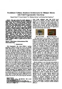
Rc f soc
fc
Fig. 1. Definitions of the radial vectors Rc and Rsoc .
where rij is the distance between the centers of the circles describing the agents, dij is the sum of the radii of the circles, and the vector nij is the unit vector pointing from the agent j to i. For a three circle representation of agents, the circles used in Eq. 3 are those circles of the two agents, which are closest to each other. The angle φij is the angle between the direction of the motion of the agent i feeling the force and the direction to the agent j, which is exerting the repulsive force on the agent i. The parameters Ai and Bi describe the strength and spatial extent of the force, respectively. The parameter λi controls the anisotropy of the social force. If λi = 1, then the force is symmetric and if it is 0 < λi < 1, the force is larger in front of an soc agent than behind. The psychological wall–agent interaction, fiw , is treated similarly, but values Aw , Bw , and λw are used for the force constants. c The physical contact force between the agents, fij , is given by ( ) c n t fij = kij (dij − rij ) + cd ∆vij nij + κij (dij − rij )∆vij tij ,
(4)
t is the difference of the tangential velocities of the circles in conwhere ∆vij n tact, ∆vij is the difference of their normal velocities, and vector tij is the unit tangential vector of the contacting circles. This force applies only when the circles are in contact, i.e., dij − rij ≥ 0. The radial elastic force strength is given by the force constant kij and the strength of the frictional force by the force constant κij . Note, that Eq. 4 contains also a physical damping force with a damping parameter cd that was added by Langston et al. [?]. The original model by Helbing et al. did not have this force. This parameter reflects the fact that the collision of two humans is not an elastic one. c The physical wall–agent interaction, fiw , is treated similarly and same force constants are used. Equations 1–4 describe the translational degrees of freedom of the agents. The rotational degrees of freedom are treated similarly, i.e., each agent has its own rotational equation of motion:
Iiz
d2 φi (t) = Miz (t) + ηiz (t) , dt2
(5)
6
H. Ehtamo, S. Heli¨ ovaara, S. Hostikka, and T. Korhonen
where φi (t) is the angle of the agent i at time t, Iiz is the moment of inertia, ηiz (t), is a small random fluctuation torque, and Miz (t) is the total torque exerted on the agent by its surroundings Miz = Mic + Misoc + Miτ ,
(6)
where Mic , Misoc , and Miτ are the torques of the contact, social, and motive forces, respectively. The torque of the contact forces is calculated as ∑( ) c Mci = Rci × fij , (7) j̸=i
where Rci is the radial vector, which points from the center of agent i to the point of contact, see Figure 1. In FDS+Evac, also the social forces exert torques on the agents and these are given by the formula ∑( ) soc Rsoc × fij , (8) Msoc = i i j̸=i
where only the circles, which are closest to each other, are considered. The vector Rsoc points from the center of agent i to the fictitious contact point i of the social force, see Figure 1. Analogous to the motive force, the first term on the right hand side of Eq. 2, a motive torque is defined as Miτ =
) Iiz ( 0 ) Iiz ( 0 0 (φ (t) − φ )ω − ω(t) = z ω ˜ i − ω(t) , i i τiz τi
(9)
where ω 0 is the maximum target angular velocity of a turning agent, ω(t) the current angular velocity, φi (t) the current body angle, and φ0i is the target angle, i.e., where the vector vi0 is pointing. The target angular speed, ω ˜ i0 , defined in Eq. 9 is larger when the body angle differs much from the desired movement direction. Langston et al. [?] used a different formula for the motive torque, which had a form of a spring force. During this work, it was noticed that a force like that will make agents to rotate around their axis like harmonic oscillators and, thus, some angular velocity dependent torque should be used. The agent movement method presented in Eqs. 1–9 has many parameters. Some of these parameters are related to physical dimensions of humans, like mi and Iiz , but many parameters are related to the chosen model. Some of these parameters are chosen to be the same as found in the literature [?, ?] and some are estimated from test calculations. The parameters of the social force were chosen such that the specific flows through doors and corridors were appropriate. The parameters of the contact forces and the rotational degrees of freedom for the three circle representation of the agents were selected mainly by trial and error in order to obtain reasonably realistic looking movement.
Modeling Exit Selection with Best Response
7
Monte Carlo simulations were done to see, which are the most important model parameters and further analysis was focused on those parameters. The many different social force parameters and others were chosen after doing quite extensive Monte Carlo runs and parametric studies. These tests and runs are described also on the published version of the FDS+Evac manual [?] and they were done using the previous version of FDS+Evac. The Monte Carlo simulations and parametric studies were rerun with the present FDS+Evac version 2.2.0 and the results of those simulations are reported in the manual on the FDS+Evac web page. The results were more or less the same as in the published manual version, because there are no modifications in the main human movement algorithm between versions 2.2.0 and 2.1.2 other than the counterflow model presented in this paper, because the geometries and agent populations were generally such that there was no counterflow in these test simulations. It should be noted that the FDS+Evac 2.2.0 uses (by default) a value of λi =0.3 for the anisotropy parameter of the social force whereas the older versions of the program used 0.5 as the default value. The older versions used also the present default value 0.3 for many of the test cases and now these results were preferred, because they produce a little bit longer evacuation times, i.e., they are more on the safe side. The present values for all the parameters used in FDS+Evac may find in the latest FDS+Evac manual, which is on the FDS+Evac web pages (http://www.vtt.fi/fdsevac/ ).
3 Counterflow Collision Avoidance Model The FDS+Evac versions 2.1.2 and older were not well suited for situations where there are human flows going in two different directions in confined spaces. A quite extreme example is the IMO test case 8 [?], where two 10 m times 10 m rooms are connected with a single 10 m long and only 2.0 m wide corridor and both rooms are initially populated with 100 agents who try to pass the narrow corridor in opposite directions. To overcome this deficiency of FDS+Evac a short range collision avoidance algorithm was introduced in FDS+Evac version 2.2.0. The basic idea is to divide the front sector of an agent to three overlapping sectors, whose centers are pointing to the left, straight ahead, and to the right, see Fig. 2. The directions of the centers of the sectors are pointing in directions −θ, 0, and +θ and each sector is 2θ wide, where θ is 40 degrees if the agent is moving with its target speed v0 and increasing towards 45 degrees when the velocity goes towards zero. When the velocity goes towards zero, also the sectors are moved a little bit behind the agent so that agents on the sides are included in the sectors. This shift is relatively small, the maximum is little less than one torso radius behind the agent, and thus, other agents that are behind the agent can not be in the sectors. The basic idea of the introduced collision avoidance methods is to choose the best of the three sectors. This
8
H. Ehtamo, S. Heli¨ ovaara, S. Hostikka, and T. Korhonen
is formulated as an optimization problem where you give positive weighting for the good sectors and negative weighting for the bad sectors depending on positions and movement velocities of the other agents. Negative weighting is added to the sectors if there are walls present so that the agent does not choose a direction where it would bang its head towards a wall. The sectors are not uniform in shape but have a longer range in the center than on the sides. It should be also noted that the ranges of the sectors are not very large. The front sectors extends maximally 3.0 m ahead of the agent, on the sides the range is 1.5 m, and in between the range varies along the cosine function. If the velocity of the agent is slow then the range is approaching a 1.5 m semicircle.
Fig. 2. The definition of the sectors used in the short range collision avoidance model.
The agents of the sectors are divided to counterflow and non-counterflow agents by projecting their velocities along the desired moving direction of the current agent. The weighting factors for different sectors depend on the counterflow or not property and also on the relative projected velocity, vp , of the agents along the vi0 direction. If the agent is counted as a non-counterflow agent the sector gets a weight cd f + dd f vp and if the agent is a counterflow agent then the sector is given a negative weight −cc f − dc f |vp |. The sectors are given relatively large negative weights using parameters c1w and c2w if there are walls present. The first weight depends on the agent speed and the distance to the wall and the second weight is giving a large penalty if the agent is really close to a wall so that a sector pointing inside a wall will not be chosen. There is a third wall related parameter, aw,cf , which is used to reduce the magnitude of the wall-agent social force, if there is counterflow agents in the front sectors so that the agent can walk closer to a wall to avoid the agents going to the opposite direction. This takes into account the behavior that people are willing to move closer to walls when bypassed by other people. If there are no counterflow agents in the front sector then the original preferred moving direction vi0 is given a positive weight cncf + dv0 vi , where
Modeling Exit Selection with Best Response
9
vi is the speed of the current agent. This weight is also multiplied by the number of the agents in the front sector so that the side sectors are not preferred “accidentally”, for example when the agents are queueing at the doors. Without the preference of the center section the agents some time started to move sideways around the end of the queue at the door, which seemed not to be too realistic behavior. To take the right over left (or the other away around) behavior into account [?], the front sector is given a positive weight |cv0 |vi and the right and left sector weights +cv0 −cv0 , respectively. So the front sector is preferred more if the agent is moving fast. The social force parameters Ai , Bi , and τi are changed when there is strong counterflow and the speed of the current agent is slow, as it usually is in this situation. The social force strength is reduced by a factor Amin,cf at most (low speed, many counterflow agents in front) and the range of the force is reduced by a factor bmin,cf . This allows higher densities for the counterflow situation. Also both the translational and rotational motive force of the agent z are increased by reducing the relaxation time constants to τmin and τmin at most, respectively. When an agent faces a strong counterflow and its movement speed is reduced below 30 % of its unimpeded walking speed, its target motive angle of the body is changed to 85 degrees, i.e., the agent tries to move shoulder first. The definition of the strong counterflow is that there is more counterflow agents in the front sector than non-counterflow agents. The target angle is changed similarly if the agent is close to a wall and there are counterflow agents that make it difficult to move ahead.
4 Sensitivity of the Counter Flow Algorithm The agent movement algorithm to deal with counter flows in FDS+Evac has many parameters. To test the relative importance of these parameters, Monte Carlo simulations were performed to find the parameters, which have the greatest effect on specific flows. The calculations were done using Evac version 2.2.0. Two different geometries were used in the Monte Carlo simulations. One was the door geometry shown in Fig. 5, where 1.0 m and 2.0 m wide doors were used. There were 100 agents randomly located at the 5 × 5 m2 square in the door flow calculations. The other test geometry was the IMO test case 8 geometry, which has two 10 m times 10 m rooms connected by a 10 m long corridor. Corridor widths of 2.0 m and 4.0 m were used and both rooms contained initially 100 agents. The monitored output quantity was the specific flow in the door geometry and for the corridor case the entering time of the last agent from the left room to the right room was recorded. The Spearman’s rank correlation coefficients (RCC) were calculated for these four cases and they are shown in Figure 3. Thousand simulations with different random
10
H. Ehtamo, S. Heli¨ ovaara, S. Hostikka, and T. Korhonen
Fig. 3. Rank correlation coefficients (RCC) for the emptying time through doors and corridors. Door widths 1.0 m and 2.0 m were used for doors and widhts of the corridors were 2.0 m and 4.0 m were used for corridors in the IMO test case 8 geometry.
initial properties were performed for each of these four different cases. The default “Adult” agent type of FDS+Evac was used in the calculations, but in total 15 different parameters of the counterflow model were varied about their means using uniform distributions. According to the RCC calculations some of the most important parameters of the counter flow model were examined further by doing parametric studies, where different parameters were varied separately and 100 simulations were done for each discretely chosen value of the parameters. Chosen geometries were the IMO test case geometry with 2.0 m wide corridor and door geometries with 1.0 m and 2.0 m wide doors, but these were not used for all the chosen model parameters. Only those parameter vs. geometry cases were run where the RCC were reasonably large. The results are shown in Figure 4. It can be seen that the chosen model for the collision avoidance does not have a large effect on the flows through doors if reasonable parameter values are used. This is a good result, because the intention was not to change the calculated flows through doors in situations where there is no counter flow. The earlier versions of FDS+Evac were already doing a nice job in these situations. For the counterflow test case, IMO test 8, there can be some variations of the results as the different parameters are varied, but these variations are not generally large and in quite many cases are within the error bars (the error bars in the figures are one standard deviation long). Finally it was decided to use the values given in Table 2 for the different parameters of the counter flow model. These parameters are probably not optimal for counter flow, but they are at least working moderately good. And changing them a little bit would not affect the outcome of the calculation
Modeling Exit Selection with Best Response
11
Table 2. The default values used for the short range collision avoidance algorithm in FDS+Evac. Most of the values are just dimensionless factors but the two minimum relaxation time constants have dimensions. cdf ddf ccf dcf c1w c2w cv0 dv0 cncf amin,cf bmin,cf aw,cf cτ τmin z τmin
0.5 1.0 1.0 2.0 5.0 10.0 1.0 1.0 0.5 0.5 0.3 1.0 0.25 0.1 s 0.05 s
Prefer agents same direction Prefer agents same direction Dislike agents opposite direction Dislike agents opposite direction Dislike directions towards walls Dislike much if going if too close to a wall If counterflow, prefer straight ahead + right Prefer v0 if no counterflow Prefer v0 if no counterflow If counterflow decrease social force If counterflow decrease social force If counterflow decrease social force If counterflow increase motive force If counterflow increase motive force If counterflow increase motive force
much. If there would be nice experimental data for a test case like the IMO test 8 then the model parameters (and the model also) could be adjusted to represent the experimental findings better. For now the collision avoidance method is quite short range and it does not try to model the wayfinding of real humans in crowds too realistically. The main idea of the model is to enable counter flow with reasonably high agent densities using a short range collision avoidance. The parameters, which are used to avoid the directions towards walls in the collision avoidance algorithm, are mainly chosen by trial and error. It was checked that these were not affecting the “normal situation” (no counterflow) and that in counterflow situations the agents did not try to push too hard against the walls in some different geometries. Some other parameters were chosen similarly by checking their possible ranges so that they did not change the behavior of FDS+Evac, when there was no counterflow. For example, if there is crowding but every agent is trying to go more or less towards the same direction, then the original vi0 direction is preferred. For this kind of short range collision avoidance method it is better that the agents are not changing their behavior when there is no counterflow.
5 Collision Avoidance Model Validation As mentioned in the previous section, it is essential to validate that after implementing the collision avoidance model, FDS+Evac will still give realistic results in normal unilateral flows. This section describes two test cases,
12
H. Ehtamo, S. Heli¨ ovaara, S. Hostikka, and T. Korhonen
where the FDS+Evac predictions are compared to experimental data on human flows on horizontal paths and to other simulation programmes on specific flows through doors. These calculations were done using Evac version 2.2.0. Many other verification and validation cases can be found on the FDS+Evac manual [] and on the FDS+Evac web page. Note that the latest published FDS+Evac manual [] refers to version 2.1.2. The current manual (for programme version 2.2.0) can be found on the web page. In the research of pedestrian flows, the dependence of the specific human flow rate on the human density is called “fundamental diagram”. It shows how the specific flow first increases when the human density is increased, but then starts to decay as the density becomes high enough to hinder the walking. In this test case, the specific flow rates given by the FDS+Evac code are compared to experimental walking velocities on horizontal floors in corridor geometry. The geometry is shown in Figure 5. The corridor is modeled as a loop to avoid the effects of inflow and outflow boundary conditions. In Figure 6, the predicted flow rates are compared against some experimental results for pedestrian traffic flows taken from Daamen’s thesis [?]. Note that almost all of the experimental information is obtained by studying bidirectional pedestrian flows, the results for unidirectional flows might give different results. The FDS+Evac simulations were performed with two different parameter sets, labels “default” refer to the defaults of FDS+Evac and labels “fast” refer to parameter sets, where λi = 0.5 is used for the anisotropy parameter of the social force. The second test geometry is the same one as used in Section ?? for human parameter sensitivity studies and it is shown on the left hand side in Figure 5. This geometry is commonly used in literature to calculate the specific flows through doors. In the test, there are 100 agents randomly located at the 5×5 m2 square. In Figure 7, the results of FDS+Evac simulations for specific flows through doors are compared to simulation programs Simulex and MASSEgress [?]. Each FDS+Evac calculation is repeated 100 times and the averages and error bars (one standard deviation) are shown in the figure. The results of MASSEgress and Simulex are extracted from Pan’s thesis [?]. The FDS+Evac simulations are performed with two different parameter sets, labels “Male”/“Female”/“Adult”/“Elderly” refer to the corresponding default agent types of FDS+Evac and labels “Male 2”/“Female 2”/“Adult 2”/“Elderly 2” refer to parameter sets, where λi = 0.5 is used. It is seen that FDS+Evac is able to produce reasonable flows through doors. For some applications, the flows generated by the default parameter values may be considered too low, but it is quite straightforward to modify the parameters of FDS+Evac to reach specific flows that are more relevant to a specific egress case. The present default value was chosen to be on the safe side.
Modeling Exit Selection with Best Response
13
6 Test Simulations We examine the functioning of the collision avoidance model with test simulations in different scenarios. The model’s performance is analyzed both qualitatively and by comparing its results to other models and experimental data. 6.1 Corridor To analyze the effect of the model in a counterflow situation, we ran simulations in the IMO test geometry 8 where a 2m wide corridor connects two rooms. There are 100 agents in one room and one agent in the other one. All agents are set to enter the corridor simultaneously trying to move to the other room. When the simulation is ran with the original social force model, the single agent gets pushed out of the corridor by the crowd. As illustrated in Figure 8, the agent collides head on with the oncoming agents and is unable to enter the corridor until the whole crowd has passed it. This result is clearly unrealistic and the need for a better model for such situations is obvious. Using the collision avoidance model, the single agent is able to penetrate through the oncoming crowd as illustrated in figure 9. At first the agents dodge each other and the single agent ends up against the wall on the right hand side of the corridor. Then the agent moves along the wall while rotating its shoulders and the crowd tries to avoid colliding with the agent. It takes 25 seconds for the single agent to pass the corridor and the crowd. Qualitatively observing, the actions of the agents appear to be rather realistic in this test case. 6.2 Intersection An intersection of two wide corridors with agents moving to all four directions was simulated. The results show that with relatively high densities the intersection gets completely blocked without the collision avoidance but is very fluent when the model is used. From the simulation snapshot of figure 10 it can be noticed that the agents moving to same directions tend to create lines. This is a well known phenomenon that has been observed in real crowds and modeled in several articles. A similar geometry was also simulated with the active walker model [8], which was said to sometimes produce roundabout traffic with the rotation direction changing from time to time. The roundabout traffic can be observed also in our simulations. However, the rotation direction is counterclockwise and it does not change during the simulations or from one simulation to another. This is likely to be due to the agents’ tendency to dodge to the right rather than to the left.
14
H. Ehtamo, S. Heli¨ ovaara, S. Hostikka, and T. Korhonen
6.3 Merging Flows We also examined whether the model effects situations where two flows merge into one. Simulations were ran for a test case where two narrow corridors merge at a right angle as illustrated in figure 11. When using the original social force model, 57.4% of the agents that made it to the exit were gray and 42.6% were black. The application of the collision avoidance model increased the proportion of the gray agents to 59.3%, but the difference to the original model is not statistically significant. However, these results differ slightly from the the buildingEXODUS model, which produces nearly equal flows from both lines over a long time interval [13]. Experimental data would be needed to analyze and compare how realistic the models are.
7 Conclusions This article presents how the widely used social force model [5] can be extended to better describe counterflow situations. The original social force model works well in situations where all agents are trying to move to the same direction but is found to create unrealistic jams and collisions in counterflow. We present a new approach where the agents try to avoid collisions by adjusting their walking directions and by rotating their shoulders. In previous approaches the shoulder rotation has not been considered and the agents have only been able to dodge one other agent at a time. In our model, agents compare different walking directions and select the one with the least counterflow. This way the agents are able to dodge multiple agents at a time, which is essential in dense crowd situations. The fact that the cross-section of a human body is not a circle but rather an ellipse is considered by using a three-circle model for the agents’ bodies [7]. The original three-circle model described the rotation of the agents with a spring force, which resulted in unrealistic oscillation in their positions. We show how a damping term can be added to the rotation equations of the original three-circle model to achieve more realistic motion. Qualitative analysis of test simulations show that the avoidance actions of the agents appear to be realistic in both dense and sparse crowds. When comparing the results to the original social force model, which essentially has no collision avoidance feature, the improvement is significant. In addition to the collision avoidance behavior, the model seemed to create behavior where agents moving to the same direction end up walking along the same path. This lane formation phenomenon has been observed in real crowds and is modeled in several articles. It is interesting to notice that our simple model is able to create rather realistic behavior in all kinds of counterflow situations. The effect of the model’s parameters was dissected using Monte Carlo method and the parameter values were selected according to these results. We also ran validation simulations with the new model in normal one directional
Modeling Exit Selection with Best Response
15
flows through exits and corridors to make sure the new model does not affect the well functioning properties of the original social force model. It turned out that the model has no effect on unilateral flows, which is an important result for the applicability of the model. A potential topic for future research would be to make real life experiments of pedestrian counterflow in different situations and compare the results to the model.
References 1. T. Korhonen, S. Hostikka, S. Helivaara, H. Ehtamo, and K. Matikainen. Integration of an agent based evacuation simulation and the state-of-the-art fire simulation. In Proceedings of the 7th Asia-Oceania Symposium on Fire Science & Technology, 2007. ovaara, H. Ehtamo, and K. Matikainen. 2. T. Korhonen, S. Hostikka, S. Heli¨ Fds+Evac: Evacuation module for fire dynamics simulator. In Proceedings of the Interflam2007: 11th International Conference on Fire Science and Engineering, 2007. 3. S. Hostikka, T. Korhonen, T. Paloposki, T. Rinne, K. Matikainen, and S. Heli¨ ovaara. Development and validation of fds+evac for evacuation simulations, project summary report. VTT Research Notes 2421, VTT Technical Research Centre of Finland, 2007. ISBN 978-951-38-6981-6; 978-951-38-6982-3. 4. K. McGrattan, B. Klein, S. Hostikka, and J. Floyd. Fire Dynamics Simulator (Version 5) User’s Guide. National Institute of Standards and Technology, 2008. 5. D. Helbing, I. Farkas, and T. Vicsek. Simulating dynamical features of escape panic. Nature, 407:487–490, 2000. 6. D. Helbing and P. Molnr. Social force model for pedestrian dynamics. Physical review E, 51(5):4282–4286, 1995. 7. P. A. Langston, R. Masling, and B. N. Asmar. Crowd dynamics discrete element multi-circle model. Safety Science, 44:395–417, 2006. 8. D. Helbing, P. Molnr, and F. Schweitzer. Computer simulations of pedestrian dynamics and trail formation. In Evolution of Natural Structures, Proceedings of the 3rd International Symposium of the SFB 230, Stuttgart, pages 229–234, 1994. 9. A. Schadschneider, C. Burstedde, K. Klauck, and J. Zittartz. Simulation of pedestrian dynamics using a 2-dimensional cellular automaton. Physica A, 295:507–525, 2001. 10. A. Smith, C. James, R. Jones, P. Langston, E. Lester, and J. Drury. Modelling contra-flow in crowd dynamics dem simulation. Safety Science, 47:395–404, 2009. 11. N. Pelechano, J. Allbeck, and N. Badler. Controlling individual agents in highdensity crowd simulation. In ACM SIGGRAPH / Eurographics Symposium on Computer Animation (SCA’07), 2007. 12. T. Kretz, A. Grnebohm, M. Kaufman, F. Mazur, and M. Schreckenberg. Experimental study of pedestrian counterflow in a corridor. Journal of Statistical Mechanics: Theory and Experiment, 2006:2527–2539, 2006. P10001.
16
H. Ehtamo, S. Heli¨ ovaara, S. Hostikka, and T. Korhonen
13. E. R. Galea, G. Sharp, and P. J. Lawrence. Investigating the representation of merging behavior at the floorstair interface in computer simulations of multifloor building evacuations. Journal of Fire Protection Engineering, 18:291–316, 2008.
Modeling Exit Selection with Best Response
17
Fig. 4. Effects of different counterflow model parameters on the specific flows through doors and on the emptying time of the left room for IMO test case 8. The corridor in the IMO case is 2.0 m wide, and two different doors widths, 1.0 m and 2.0 m, are used.
18
H. Ehtamo, S. Heli¨ ovaara, S. Hostikka, and T. Korhonen
Fig. 5. Test geometries used to calculate the specific flows through doors and corridors.
Modeling Exit Selection with Best Response
Fig. 6. The specific flows in corridors.
19
20
H. Ehtamo, S. Heli¨ ovaara, S. Hostikka, and T. Korhonen
Fig. 7. The specific flows through doors.
Fig. 8. Snapshots of a simulation with the previous model. The agents are unable to avoid collisions and the single agent gets pushed out of the corridor in an unrealistic manner.
Modeling Exit Selection with Best Response
21
Fig. 9. Simulation snapshots using the collision avoidance model. The single agent is able to pass the crowd in 25 seconds.
Fig. 10. Snapshot of the simulation in the crossing. The black agents are moving horizontally and the gray ones vertically.
22
H. Ehtamo, S. Heli¨ ovaara, S. Hostikka, and T. Korhonen
Fig. 11. The geometry used in the test case.