Computing the intersection or the minimum distance between objects also ... and Q. Intuitively, we may think of P as continually expanding until it reaches M â¡ P ...
HKU CS Tech Report TR-2005-01
Collision Detection of Convex Polyhedra Based on Duality Transformation Yi-King Choi § , Xueqing Li † , Wenping Wang § , Stephen Cameron ‡ § †
Department of Computer Science, The University of Hong Kong, Hong Kong
College of Computer Science and Technology of Shandong University, P.R. China ‡
Computer Laboratory, Oxford University, United Kingdom
Abstract Collision detection is an essential problem in many applications in computer graphics, CAD/CAM, and robotics. In this paper, a new method, called CD-Dual, for detecting collision between two convex polyhedra is proposed. The idea is based on a local search among the faces on the Minkowski difference (M ) of the polyhedra. The local search is guided by a simple signed distance function defined on the dual polyhedron of M . Due to the convexity of the dual polyhedron, it is guaranteed that the result of the local search will lead to a vertex on the dual polyhedron that attains the global maximum signed distance, and this distance tells whether the two polyhedra overlap.
1
Introduction
Collision detection is one of the major subjects in robotics and computer graphics, or other areas that simulate physical environments [10]. Collision detection is to determine whether two moving objects collide or not at any moment. The ability to efficiently detect collision is critical in these applications since system responses are often based on the collision status of the objects. A typical approach is to determine whether two objects intersect at sampled time steps. Although collision occurring between two consecutive steps may be missed, this kind of errors can be reduced by decreasing the sampling time interval. Since objects’ orientations and positions differ only slightly between successive time steps for objects with continuous motion, geometrical and temporal coherences can be exploited by making use of witness information, such as a separating plane [1], computed at a previous step. Various approaches to detecting collision between convex polyhedra have been studied in the literature. One of these is the use of techniques from computational geometry. Voronoi diagrams are used to keep track of the closest features between pairs of objects 1
in [5, 11]. I-COLLIDE [5] employs the “sweep-and-prune” technique to reduce the number of pairs of objects whose collision status is to be considered. While most algorithms are designed for convex objects, some work (e.g. [12]) has also been done for non-convex objects. Computing the intersection or the minimum distance between objects also serve as an alternative approach to collision detection. An O(log2 n) algorithm for polytope-polytope collision detection is given in [7], with the use of the hierarchical representation of a polytope. A commonly used method, GJK [9], that computes the distance between convex polyhedra makes use of the Minkowski difference and convex optimization techniques to compute the closest points. Modified approaches [3, 4] and improved implementations [2] based on GJK have been developed. It is also shown in [4] that an enhanced version of GJK has O(1) time cost under the assumption of strong geometric coherence. Most existing methods are efficient when the distance between two objects is large or when two objects penetrate each other deeply. However, they become less efficient when the objects are very close to each other or just penetrate slightly. In this paper, we present a new algorithm, CD-Dual, to detect collision between two convex polyhedra based on duality transformation. The algorithm is shown to be fast even in the case when the separating distance or penetration distance is small; thus it exhibits a more balanced running time for all collision configurations. Detailed theoretical analysis and experimental results are also discussed.
2
Preliminaries
In this section, we shall give the definitions that are used in this paper. Also, the concept of duality will be described. A convex polyhedron P in E3 can be defined as the intersection of half-spaces defined by some planes in E3 . Let V(P ), F(P ), and E(P ) denote the set of vertices, faces, and edges of P , respectively. Definition 1 By considering two polyhedra P and Q as two point sets, P and Q are said to be overlapping if P ∩ Q 6= 0; otherwise, they are separate. Definition 2 Let V(P ) denote the set of the vertices of a polyhedron P in E3 . A supporting vertex p of P in the direction s 6= 0 is a vertex in V(P ) such that s · p = max{s · p′ |p′ ∈ V(P )}, where x · y is the dot-product of the vectors x and y. Note that for a supporting vertex p of P in the direction s, we have s·p = max{s·p′ |p′ ∈ P }. We may also define the supporting edge or supporting face of P in s as the edge and face that contains two or more supporting vertices in s.
2.1
Minkowski Sum of Two Polyhedra
¯ = {¯ Given two polyhedra P and Q, let Q q | − q¯ ∈ Q}. We consider the Minkowski sum ¯ defined by M ≡ P ⊕ Q ¯ = {p + (−q)|p ∈ P, q ∈ Q}. Since P and Q are M of P and Q 2
convex polyhedra, M is a convex polyhedron. It can be shown [9] that P and Q overlap if and only if M contains the origin 0, i.e., 0 ∈ M . ¯ is in fact the Minkowski difference of P The Minkowski sum of two polyhedra P and Q ¯ and Q. Intuitively, we may think of P as continually expanding until it reaches M ≡ P ⊕ Q while Q continually shrinking until it becomes the origin 0. If M contains the origin 0, we have p − q = 0 and therefore p = q for some p ∈ P and q ∈ Q. It means that P and Q share a common point, i.e., they overlap. Otherwise, if 0 6∈ M , we have p − q 6= 0 for all p ∈ P and q ∈ Q. Therefore, P and Q are separate. The faces in F (M ) may be classified into the following three subsets (Figure 1): Ff v
P
Fvf
Fee
¯ Q ¯ M ≡P ⊕Q ¯ Faces on M can be classified as of type Ff v , Figure 1: The Minkowski sum M of P and Q. Fvf , or Fee . ¯ Ff v : Each face F (fp , vq¯) is a point set {x+vq¯|x ∈ fp }, where fp ∈ F(P ) and vq¯ ∈ V(Q) ¯ ˆ fp , the normal vector of fp . is the supporting vertex of Q in the direction n ¯ and vp ∈ V(P ) Fvf : Each face F (vp , fq¯) is a point set {vp +x|x ∈ fq¯}, where fq¯ ∈ F(Q) ˆ fq¯ , the normal vector of fq¯ . is the supporting vertex of P in the direction n Fee : Each face F (ep , eq¯) is a parallelogram with vertices (v0 , v1 , v2 , v3 ) where v0 = vp0 + vq¯0 , v1 = vp1 + vq¯0 , v2 = vp1 + vq¯1 , v3 = vp0 + vq¯1 with vp0 , vp1 ∈ V(P ) ¯ forming an edge forming an edge ep = (vp0 , vp1 ) ∈ E(P ) and vq¯0 , vq¯1 ∈ V(Q) ¯ eq¯ = (vq¯0 , vq¯1 ) ∈ E(Q). Moreover, the Gaussian images of ep and eq¯ intersect on the unit sphere S 2 . Remark 1 The Gaussian image G(P ) of a polyhedron P is a graph embedded on the unit sphere S 2 that is obtained as follows (Figure 2): A face f ∈ F(P ) is transformed to a ˆ ∈ S 2 where n ˆ is the unit normal vector of f . An edge e ∈ E(P ) adjacent vertex S(f ) = n to two faces f0 , f1 ∈ F(P ) is transformed to a great arc A(e) connecting two vertices S(f0 ) 3
and S(f1 ) on S 2 . In fact, G(P ) is a connected network on S 2 and each region of G(P ) corresponds to a vertex vi ∈ V(P ) denoted by RP (vi ). G(P ) P
v0 S(f0 )
A(e1 )
f0 e1 e0
f1
RP (v0 )
f2 S(f1 )
S(f2 )
A(e0 ) A(e2 ) e2
Figure 2: A polyhedron P and its Gaussian image G(P ) on S 2 . Remark 2 The Gaussian image of a feature (vertex, edge or face) φ of a polyhedron P is the set of normal directions of planes that that may come into contact with P at φ. In other words, φ is the supporting feature of P in the directions represented by its Gaussian image. ¯ (denoted by G(M )) can be obtained by Remark 3 The Gaussian image of M = P ⊕ Q ¯ Each vertex in G(M ) corresponds to superimposing the Gaussian images G(P ) and G(Q). a face of M . Figure 3 shows how three kinds of vertices in G(M ) are related to the three types of faces in F(M ) described above.
G(P )
¯ G(Q)
G(M )
Figure 3: The planar representation of the Gaussian image G(M ) by superimposing G(P ) ¯ There are three types of vertices in G(M ): (i) (white point) a vertex of G(P ) and G(Q). ¯ i.e., a face in Ff v ; (ii) (black point) a vertex of G(Q) ¯ falling falling within a region of G(Q), within a region of G(P ), i.e., a face in Fvf ; and (iii) (shaded square) a vertex formed by ¯ i.e., a face in Fee . two intersecting arcs from G(P ) and G(Q),
4
2.2
Duality
Let a plane L in E3 be given by ax+by +cz = d, d 6= 0. The duality transformation denoted ˆ 3 . A point u = (r, s, t)T in by D maps L to a point l = (a/d, b/d, c/d)T in the dual space E 3 3 ˆ . A plane passing through E is transformed by D to a plane U : rx + sy + tz = 1 in E 3 3 ˆ the origin in E is mapped to a point at infinity in E . The origin in E3 is transformed to ˆ 3 . In fact E3 is also the dual space of E ˆ 3 . See [8, 14] for more the plane at infinity in E about duality transformation. There is thus a one-to-one correspondence between a plane ˆ 3 . Table 1 summarizes some important properties of (point) in E3 and a point (plane) in E 3 ˆ 3: a polyhedron P in E and its dual Pˆ in E Table 1: Properties of a polyhedron P under a duality transformation. In E3 P is convex a face in F(P ) a vertex in V(P ) P contains the origin a point x inside P a point x outside P
3
ˆ3 In E Pˆ is convex a vertex in V(Pˆ ) a face in F(Pˆ ) ˆ P contains the origin the plane D(x) does not intersect Pˆ the plane D(x) intersects Pˆ
The Algorithm
In this section, we shall present our algorithm to detect collision between two convex polyhedra. We first give the basic idea of the algorithm.
3.1
Basic Idea
¯ be their Minkowski difference. Let P and Q be two convex polyhedra in E3 and M ≡ P ⊕ Q 3 Let o be the origin of E and c any fixed point inside M , with c 6= o. Consider a translation T : E3 7→ E3T such that c′ = T (c) is the origin of E3T (Figure 4). Let o′ = T (o) = −c and M ′ = T (M ). Since c ∈ M , M ′ must contain the origin. Next, we apply a dual ˆ 3 that maps o′ to a plane o ˆ and the polyhedron M ′ to a transformation D : E3T 7→ E T ˆ . As o′ is not the origin, o ˆ is not the plane at infinity. Also, the plane o ˆ polyhedron M ′ ′ ˆ intersects M if and only if o 6∈ M . Hence, we have P and Q overlap
⇔ o∈M ⇔ o′ ∈ M ′ ˆ. ˆ does not intersect M ⇔ o
5
T
D
M
M′
o
ˆ M
ˆ o
′
o
c
′
c E3
ˆ3 E T
E3T
ˆ and o ˆ are obtained. Note that if o 6∈ M , o ˆ intersects Figure 4: A 2D illustration of how M ˆ M. ˆ in order to detect ˆ intersects the polyhedron M Therefore, we just need to test if the plane o if P and Q overlap.
3.2
Signed Distance Function
Recall the signed distance of a point p = [x0 , y0 , z0 ]T to a plane L : AT x = k which is given by dL (p) = AT p − k, where A = [l, m, n]T is the unit normal of L, x = [x, y, z]T , and k > 0 is the perpendicular distance of the origin 0 to the plane. Note that, if p lies on L, dL (p) = 0; if p lies on the same side of L as 0, dL (p) < 0; and if p lies on the opposite side of L to 0, dL (p) > 0. ˆ to the plane o ˆ is ˆ . Since M Let d′ be the maximum signed distance of all points in M ′ ˆ to the plane o ˆ must convex, the point that attains the maximum signed distance d on M ˆ lie on the boundary of M , i.e., either on a vertex, a face or an edge. In any case, there is ˆ ) such that its signed distance to the plane o ˆ , doˆ (v), equals d′ . Hence, a vertex v ∈ V(M ˆ ˆ. we may consider only the signed distance of all vertices of M to the plane o ′ ˆ ˆ ˆ as the origin and therefore M If d < 0, all vertices on M are on the same side of o ′ ˆ do not intersect. Otherwise if d > 0, at least one vertex is at the opposite side of and o ˆ and we conclude that P and Q do not ˆ to the origin, which implies that o ˆ intersects M o ˆ at some boundary point. So o lies on the boundary ˆ touches M overlap. When d′ = 0, o 3 of M in E . By the construction of M as described in section 2.1, o = p − q for some boundary points p and q of P and Q, respectively. It implies that p = q and P and Q share a common boundary point. In this case, P and Q touch each other. ˆ ) be its corresponding dual vertex under D ◦ T . ˆ ∈ V(M Let f be a face in F(M ) and v We may then define the signed distance of f denoted by d(f ), to be the signed distance ˆ to the plane o ˆ , i.e., doˆ (ˆ v). Let Hf be the plane containing f with plane equation of v T N x = k with k > 0. Then f is translated by T to a face in F(M ′ ) with plane equation ˆ ) in the dual space. ˆ = N/(k − NT c) in V(M NT x = k − NT c. This corresponds to v 3 3 ˆ 3 is ˆ in E The origin o in E is mapped to −c in ET and therefore the plane equation of o T
6
−cT x = 1. The signed distance d(f ) can then be expressed explicitly as follows: N 1 −cT · − v) = d(f ) = doˆ (ˆ T kck k − N c kck k = − . kck(k − NT c)
(1)
Let us now take a closer look at the geometrical meaning of d(f ). The quantity d(f ) = ˆ 3 such that doˆ (x) = doˆ (ˆ ˆ ˆ in E v) for all points x ∈ L v) uniquely determines a plane L doˆ (ˆ T ˆ passes through v ˆ and is parallel to the (Figure 5). It is easy to see that the plane L 3 ˆ ˆ ˆ has the same ˆ . Let l be a point in E whose image under D ◦ T is L ∈ E3T . Since L plane o
f1
ˆ1 v l2
l1 ˆ0 v
l0
o c
ˆ M
f0 M
ˆ2 v
f2
ˆ2 L
ˆ1 L
ˆ ˆ0 o L
ˆ3 E T
E3
ˆ 3 attaining maximum signed distance to o ˆ 0 in E ˆ corresponds to a Figure 5: The vertex v T 3 face f0 in E intersecting the directed line co. The dual image of o, fi and li under D ◦ T ˆ i , i = 0, 1, 2, respectively. ˆ, v ˆ i and L are o ˆ passes through v ˆ , l must lie on the directed line co. Moreover, L ˆ and normal direction as o therefore l lies on the plane Hf containing the face f . This implies that l is the intersection of the plane Hf and the line co. Note that a larger d(f ) corresponds to a point l closer to c. If d(f ) is the largest among the signed distances of all faces in F(M ), the intersection point of the plane Hf and the line co must be the closest to the point c among all intersections between the directed line co and the planes containing the faces of M . This can happen only when the line co intersects the face f , since c ∈ M and M is convex. Now, the signed distance of c and o to the plane Hf are given by dHf (c) = −(k − NT c)/kNk and dHf (o) = −k/kNk, respectively. If d(f ) < 0, since k > 0, by Eq. (1), k − NT c > 0 and therefore dHf (c) and dHf (o) are of the same sign; thus c and o are on the same side of the face f and o ∈ M . On the other hand, if d(f ) > 0, c and o are on opposite sides of f and therefore o 6∈ M . It is now clear that we are in fact determining whether o is in M by firing a ray from an interior point c of M to o, obtaining a face of M that intersects the ray and deciding whether the intersection point lies within the line segment co, by computing the maximum 7
signed distance of all faces in M . From Eq. (1), we see that d(f ) can be computed without even applying the duality transformation on M . However, it becomes apparent that d(f ) ˆ is convex, a vertex v ˆ v) in the dual space. Since M is a convex function by considering doˆ (ˆ ˆ in V(M ) attaining a local maximum signed distance must also attain the global maximum ˆ ). signed distance among all vertices in V(M We may then define our objective function as the signed distance of a face f in F(M ) and let dmax = max{d(f )|f ∈ F(M )} denote the maximum signed distance of all faces in F(M ). Now the problem of detecting collision between two polyhedra P and Q can be transformed to finding the optimal value dmax . Starting from any face on F(M ), we can go to the next face that has the largest signed distance among all immediate neighbours of the current face. By this local search, we shall visit faces with increasing signed distance and eventually stop at a face with a locally maximum signed distance. Due to the convexity of the objective function d(f ), this local search scheme will lead to the optimal face, fopt , that attains the maximum signed distance dmax among all faces in F(M ). As a further remark, let α be the distance between the point o and the intersection of the directed line co and fopt . If P and Q are separate, α is their separating distance along the direction co, which is the distance that Q can be moved along co until it touches the fixed P . If P and Q are overlap, α is then their penetration distance along co, which is the distance that Q can be moved along co until it touches the fixed P externally. Further details can be found in section 6. The remaining problem now is to find efficiently the optimal face fopt . Note that it is possible to have more than one fopt that attain dmax . This happens when the line co intersects M at an edge or a vertex.
3.3
Searching for the optimal vertex
¯ A naive way to search for fopt is to first construct the Minkowski difference M ≡ P ⊕ Q and perform the search on the vertices in M . However, the time complexity of constructing M is O(mn) in the worst case, where m and n are the number of vertices of P and Q, respectively. Moreover, it would take a long time to traverse the faces on M by advancing one edge to the neighbour at each step. To avoid the high cost of constructing M , our searching scheme is based on three successive search phases for fopt within three subsets of the faces of M , without completely constructing M . Note that each face f ∈ F(M ) must belong to either one of the sets Ff v , Fvf or Fee . Our algorithm is to search for fopt in each of the three sets separately and successively in a local manner. Three procedures for this searching will be described in the following subsections. The correctness of these procedures are based on three theorems whose proofs can be found in the Appendix. 3.3.1
Procedure Search-FV
This procedure is to search for a face in F(M ) having the maximum signed distance among all faces in Ff v . We first choose a face f0 ∈ F(P ) with normal vector np . We may use 8
heuristic search in a preprocessing step so that the face F (f0 , v0 ) ∈ M formed by f0 and ¯ is close to fopt on M. The heuristic search for f0 will be its supporting vertex v0 in Q discussed in detailed in section 4.2. The following pseudocode describes the procedure: Procedure Search-FV (dm , fm ) = SignedDistance-FV(f0 ) For each iteration i If dm > 0, Return (dm , fm ). Obtain the n faces fi0 , fi1 , . . . , fin−1 that are adjacent to fi in P For each face fij , j (dji , fm,i ) ← SignedDistance-FV(fij ). If dm < dki , where dki = max{dji |j ∈ [0, n − 1]} k ,f k dm ← dki , fm ← fm,i i+1 ← fi ; Otherwise, Return (dm , fm ). Function SignedDistance-FV(fp ∈ F(P )) ¯ in the direction n, vq¯ ← the supporting vertex of Q where n is the normal of fp . Obtain a face fm ∈ Ff v where fm = {x + vq¯|x ∈ fp }. dm ← d(fm ) Return (dm , fm )
¯ given a direction n in the subroutine The determination of the supporting vertex of Q SignedDistance-FV can be accelerated by using the hierarchical representation of a polyhedron as described in [6]. Theorem 1 The face fm ∈ F(M ), computed by Search-FV, attains the maximum signed distance among all faces in Ff v , i.e., d(fm ) = max{d(f )|f ∈ Ff v }. 3.3.2
Procedure Search-VF
This procedure is similar to Search-FV in that it searches for the a face in F(M ) attaining the maximum signed distance among all faces in Fvf . The only difference is that the roles ¯ are interchanged and hence the pseudocode for the procedure is omitted for of P and Q ¯ from which the search is started can be chosen by brevity. The first face f0 ∈ F(Q) ¯ that is incident heuristic as for Search-VF. An alternative is to choose a face f0 ∈ F(Q) ¯ where fm = F (fp , vq¯) is the face output by Search-FV, since we have been at vq¯ in Q approaching the optimal face fopt at each step of the procedure. Theorem 2 The face fm ∈ F(M ), computed by Search-VF, attains the maximum signed distance among all faces in Fvf , i.e., d(fm ) = max{d(f )|f ∈ Fvf }.
9
3.3.3
Procedure Search-EE
By the procedures Search-FV and Search-VF, we determined the face f that attains the maximum signed distance among all faces in the set Ff v ∪ Fvf . Starting from f , we shall search for the remaining faces in Fee . ¯ As mentioned in section 2.1, Let hep , eq¯i be an edge pair with ep ∈ E(P ) and eq¯ ∈ E(Q). if the arcs that are the Gaussian images of ep and eq¯ intersect on S 2 , a face F (ep , eq¯) ∈ Fee will be formed. We shall describe in details how to determine whether two arcs intersect in section 4.3. The following procedure Search-EE makes use of a stack S to keep track of all candidate edge pairs heip , eiq¯i which might give us the face in Fee that attains the largest signed distance among all faces in Fee . Procedure Search-EE dm ← max{dm computed by Search-FV and Search-VF}. fm ← the face in Ff v ∪ Fvf that attains dm . Push to S all possible edge pair he′p , eq′¯i where e′p are edges of fp and e′q¯ are edges incident at vq¯, if fm = F (fp , vq¯), or e′p are edges incident at vp and eq′¯ are edges of fq¯, if fm = F (vp , fq¯). Repeat If dm > 0, Return (dm , fm ). Pop heip , eiq¯i from S. If heip , eqi¯i forms a face fi ∈ Fee , di ← d(fi ) If di > dm , dm ← di , fm ← fi Push to S all possible edge pairs heip , eqj¯i, hejp , eiq¯i, where ejq¯ are edges incident at the two end vertices of eiq¯, and ejp are edges incident at the two end vertices of eip . Until S is empty. Return (dm , fm ).
Theorem 6 The face fm ∈ F(M ), computed by Search-EE, attains the maximum signed distance among all faces in F(M ), i.e., fm = fopt and d(fm ) = dmax . With the above theorems and the ideas presented, the following pseudocode describes our algorithm to detect whether two convex polyhedra P and Q overlap:
10
Procedure CD-Duality(P , Q) (dmax , fmax ) ← Search-FV (dmax , fmax ) ← Search-VF (dmax , fmax ) ← Search-EE If dmax > 0 Report P and Q are Separate Otherwise Report P and Q are Overlap
4
Implementation Issues
In this section, we shall highlight several important issues in implementing our algorithm so that the computations can be carried out efficiently.
4.1
To obtain a point c inside M
To compute the signed distance for a face in M , we need to determine an interior point c ∈ M which must not be the origin. The point c can be any arbitrary point as long as it is inside M . Therefore, we might store two distinct interior points, p0 , p1 ∈ P and q0 , q1 ∈ Q, for each of P and Q. The vector differences, pi − qj , of these four interior points give rise to four distinct interior points in M , from which it is always possible to obtain an interior point of M which is not the origin.
4.2
To obtain the initial face in Search-FV
In section 3.3.1, we mentioned that a heuristic method can be used to get the initial face f0 ∈ F(P ) from where Search-FV starts. The aim of this step is to optimize the searching for fopt and therefore f0 should be chosen such that F (f0 , v0 ) is as close to fopt ¯ in the normal direction of f0 . Noting as possible, where v0 is the supporting vertex of Q ˆ is in fact the vector s = o − c from the properties of duality that the normal of the plane o (Figure 4), therefore fopt must be front-facing with respect to s with nfopt · s > 0, where nfopt is the normal of fopt . We may then take the face f0 ∈ F(P ) with normal n0 such that n0 · s is the greatest among all faces in F(P ). F (f0 , v0 ) may not be as close to fopt especially when M is flat and elongated (Figure 6) and in fact this drawback is reflected in our experiments. However, this heuristic scheme can still efficiently eliminate most back-facing faces f with normal nf in M with respect to s such that nf · s < 0.
4.3
To decide whether two arcs on S 2 intersect
In procedure Search-EE, we often need to decide whether two arcs A(ep ), A(eq¯) of the edge pair hep , eq¯i intersect on the Gaussian sphere S 2 . Therefore, the computation has to be done efficiently. Now, let a, b be the end points of A(ep ), c, d be the end points of A(eq¯) and o be the centre of S 2 (Figure 7). Ap and Aq¯ intersect if and only if (1) c, d are on 11
s=o−c fopt F (f0 , v0 )
f0 P
c
M
Figure 6: The face formed by the first face f0 chosen by the heuristic scheme may not be close to fopt in M . different sides of plane oba; (2) a, b are on different sides of plane ocd; and (3) a, b, c, d are on the same hemisphere. d
b
a
c o
d a
b
d
c
a
o
c
d
b c o
o a
(i)
(ii)
(iii)
b (iv)
Figure 7: Determining whether two arcs intersect on S 2 . Arcs intersect in (i). No intersection between arcs where (ii) only condition (1); (iii) only condition (2) and (iv) only condition (3) is violated. Consider the signed volume, |cba| = det[ c b a ], of a parallelepiped spanned by three vectors a, b, c. The quantities |cba| and |dba| are of different signs if they are at opposite sides of plane oba. Therefore, the above three conditions can be formulated as (1) |cba| × |dba| < 0; (2) |adc| × |bdc| < 0; and (3) |acb| × |dcb| > 0 since a, d lie on the same side of plane ocb and all four points will be on the same hemisphere defined by ocb. Noting that only the quantities |cba|, |dba|, |adc| and |bdc| are required, since |acb| = |cba| and |dcb| = |bdc|.
4.4
Frame Coherence
When the two polyhedra P and Q assume continuous motion from frame to frame, our algorithm may also exploit the temporal or frame coherence. At each time frame, we compute fopt either in Ff v , Fvf or Fee that attains the maximum signed distance among all faces in F(M ). In any case, we can determine quickly a face f ′ = F (fp , vq¯) ∈ Ff v that is as close to fopt as possible. For the next frame, since the position and orientation of P and Q will only have little changes, the new optimal face should also be close to fopt and the use of fp as the initial 12
face for Search-FV will lead us to the new optimal face more rapidly.
5
Results
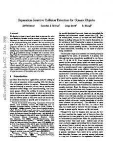
We have tested CD-Dual on a PC with a Pentium III 1.7GHz CPU. The algorithm is implemented in C++ and is compared against the enhanced version of the GJK method [4]. Since GJK computes also the minimum distance or the penetration distance of two polyhedra, its implementation has been modified so that it will complete computations once collision or non-collision is determined. Two polyhedra that are both approximations of some ellipsoids are obtained by randomly generating points on the surface of the ellipsoids. At each run, the two polyhedra are of the same ellipsoidal shape, size and number of vertices. The distance l between the two polyhedra varies and it is the distance that one object must be moved in one direction so that two objects become separate. A negative l corresponds to two penetrating objects while a positive l means that two objects are separate. For any fixed l, the orientation of one polyhedron is fixed while the other assumes 500 orientations; and 500 pairs of polyhedra are thus obtained. The two algorithms are then run on each pair of polyhedra for 300 times without using frame coherence and the average CPU time is recorded. Figure 8 shows the experimental results with the varying number of vertices of the polyhedra. It is noticed that there are some peaks in the graphs for GJK near l = 0, i.e., when the two polyhedra are close to each other or their penetration distance is small. This is because in such situations, the GJK algorithm converges slowly. In contrast, CD-Dual has an almost constant running time for cases where the two polyhedra touch (l = 0) or intersect (l < 0), no matter what the penetrating distance is. This is because the face fopt that attains the maximum signed distance has to be reached to confirm the colliding status. The graphs also show that the CPU time drops significantly for CD-Dual when the two polyhedra are separate (l > 0). The reason is that CD-Dual can determine separation once a face in M with positive signed distance is reached. The running time decreases gradually as the separating distance increases because there are more faces in M with positive signed distance and separation can therefore be determined more quickly. There is also mild increase in the running time for our algorithm when the number of vertices on each polyhedra increases. Although the graph shows favourable running time of CD-Dual over GJK, it should be reminded that the CPU time depends on the specific implementation and the optimization level of the algorithms. Figure 9 shows the CPU time of both algorithms with the shape of the approximated ellipsoid varying. Notice that CD-Dual takes longer time to complete when the ellipsoid is more elongated in shape. As explained section 4.2, M is most likely to be elongated in this case, and therefore the first chosen face in Ff v is not close to the optimal face and it takes more steps to reach the optimal face. The amount of time spent on each of the procedures Search-FV, Search-VF, and Search-EE is shown in the accumulated graph in Figure 10. Little time has been used in Search-VF since the procedure starts from the optimal face in Ff v which is often close 13
(µs) 70 Enhanced GJK 60
Average CPU Time
CD-Dual 50 40 30 20
n=1500 n=1000
10
n=500
0 0 Separating distance
-4
4
l
Figure 8: Varying number of vertices (n) on the polyhedra with a fixed size of the approximated ellipsoid (200:100:100, i.e., the sizes along the three major axes). (µs) 60 Enhanced GJK CD-Dual
Average CPU Time
50
40
30
20 n=200:180:180 n=200:100:100
10
n=200:10:10 0 -4
0 Separating distance
4
l
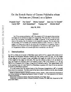
Figure 9: Varying ellipsoid shapes (a : b : c, i.e., the sizes along the three major axes) for the two polyhedra with fixed number of vertices (n = 1000). to the target face in Fvf , i.e., the face with maximum signed distance in Fvf . Search-EE takes more time to complete as there are in general more Fee -type faces in M (although most such faces have been skipped by Search-FV and Search-VF) and the computation in each step involves the more complicated arc-arc intersection when compared to the other two procedures. However, when the separation distance increases, the time needed for Search-EE drops drastically as in most of the time a face in M with positive signed distance is reached quickly and the algorithm will report separation, sometimes even within the procedures Search-FV and Search-VF. Figure 11 shows how the searches proceed in each of the procedures in a typical scenario.
14
(µs) 40
Average CPU Time
Search-EE Search-VF
30
Search-FV 20
10
0 -4
0 Separating distance
4
l
Figure 10: Accumulated graph showing time spent on each procedure with 1000 vertices on each polyhedron of size 200 : 100 : 100.
6
Estimating Minimum Separating Distance Along a Specified Direction
Let P and Q be two polyhedra. If P and Q are separate, the minimum separating distance along a direction s between P and Q is defined as the minimum distance that Q should move in the direction s (with P fixed) such that P and Q just touch each other (Figure 12(a)). ¯ such To determine this distance using CD-Dual, we may choose any point c in M ≡ P ⊕ Q that c = ks, for some constant k > 0. We first obtain two sets of points P˙ and Q˙ by applying an orthographic projection along s of all vertices of P and Q to a plane H normal to s. This projection can be done in O(m + n) time (Figure 13(a)) where m and n are the number of vertices of P and Q, ˙ of the respectively. The next step is to construct the convex hull, CH(P˙ ) and CH(Q), ˙ respectively, which can be done in O(m + n) time since the boundary points P˙ and Q, ˙ are the silhouette vertices of P and Q as viewed along s. P vertices of CH(P˙ ) and CH(Q) ˙ intersect and and Q intersect when Q is moved along s if and only if CH(P˙ ) and CH(Q) ˙ contains the origin 0. Note therefore the Minkowski difference M˙ of CH(P˙ ) and CH(Q) ˙ that M can be built in O(m+n) time. Let r˙ i = p˙ i − q˙ i be the vertices of M˙ in anticlockwise order (Figure 13(b)). We may then quickly determine in O(m + n) time whether 0 is in M˙ by examining the triangles △˙r0 r˙ j r˙ j+1 , j = 1, . . . , l − 2 where l is the number of vertices of / M˙ , the M˙ . We have 0 ∈ M˙ if and only if 0 ∈ △˙r0 r˙ j r˙ j+1 , for some j = 1, . . . , l − 2. If 0 ∈ two polyhedra P and Q do not collide no matter how far Q is moved along s or −s and the point c cannot be found. Otherwise, let (u, v, w), where u, v, w > 0 and u + v + w = 1,
15
21 1
12 10 11 13 3 5 9 4 6 8 7 2
14 15
16
17
20 18
22
19
29 24 27 25 23 28 26
30
Figure 11: Search path on M . Top: In Search-FV (dotted regions contain faces in Ff v ); Middle: In Search-VF (dotted regions contain faces in Fvf ); and Bottom: In SearchEE (gray regions contain faces in Fee ) . be the barycentric coordinates of 0 with respect to r˙ 0 , r˙ j , r˙ j+1 . Then, 0 = = = =
u˙r0 + v r˙ j + wr˙ j+1 u(p˙ 0 − q˙ 0 ) + v(p˙ j − q˙ j ) + w(p˙ j+1 − q˙ j+1 ) (up˙ 0 + v p˙ j + wp˙ j+1 ) − (uq˙ 0 + v q˙ j + wq˙ j+1 ) ˙ p˙ − q,
where p˙ = up˙ 0 + v p˙ j + wp˙ j+1 and q˙ = uq˙ 0 + v q˙ j + wq˙ j+1 . Let p = up0 + vpj + wpj+1 and 16
P
Q
M f
S
c
o
(a) fopt ≡ ux + vy + wz − 1 = 0
M′ ˆ M c′ = (0, 0, 0)T d(fopt )
g θ
vopt = (u, v, w)T
g¯ o′ = (a, b, c)T
ˆ ≡ ax + by + cz − 1 = 0 o
(b)
Figure 12: (a) The minimum separating distance between P and Q along s when they ¯ and (b) the are separate and the corresponding distance between o and M = P ⊕ Q; relationship between the minimum separating distance g and the signed distance of d(fopt ) in the dual space.
P
Q
˙ M
r˙ j+1 r˙ j
˙ {p} ˙ {q}
s
0 H
CH(P˙ ) r˙ 0
r˙ 1
˙ CH(Q)
(a)
(b)
Figure 13: (a) Orthographic projection of P and Q along s to a plane H normal to s; ˙ with the triangle △˙r0 r˙ j r˙ j+1 and (b) the Minkowski difference M˙ of CH(P˙ ) and CH(Q) containing the origin 0.
17
q = uq0 + vqj + wqj+1 , where p0 , pj , pj+1 are vertices in P and q0 , qj , qj+1 are vertices in Q that are projected to p˙ 0 , p˙ j , p˙ j+1 and q˙ 0 , q˙ j , q˙ j+1 , respectively. Since the projection of P and Q along s to the plane H normal to s is an affine transformation that preserves ratio of area and therefore barycentric coordinates, p˙ and q˙ are the projected images of p and q, respectively. We have p ∈ P and q ∈ Q because u, v, w > 0 and u + v + w = 1. ˙ we have c = p − q = ks, for some Also p − q 6= 0 as P and Q are separate. Since p˙ = q, ¯ The minimum separating distance between P constant k 6= 0 and also c ∈ M = P ⊕ Q. and Q is along s for k > 0 and along −s if k < 0. ˆ 3 and therefore the algorithm should be ˆ in E ˆ intersects M As P and Q are separate, o T modified slightly so that it keeps on searching for fopt , even if we have reached a face in M with positive signed distance. The distance between o and the intersection of fopt with the line oc is then the required minimum separating distance. Let g be the minimum separating distance. We would then establish the relationship between g and the signed distance d(fopt ). Let c′ be the origin of E3T as described in ˆ is the plane given by ax + by + section 3.1. Let also o′ = (a, b, c)T (Figure 12(b)). Then o cz −1 = 0. The face fopt ≡ ux+vy +wz −1 = 0 corresponds to the vertex vopt = (u, v, w)T ˆ 3 and g is the distance between o′ and the intersection of fopt with the line c′ o′ . ˆ in E on M T Now, d(fopt ) =
au + bv + cw − 1 √ a2 + b 2 + c 2
Let g¯ be the shortest distance from the point o′ to the face fopt and θ be the angle between the line c′ o′ and the normal vector of fopt . Then ua + vb + wc − 1 √ , and u2 + v 2 + w 2 au + bv + cw √ cos(θ) = √ . a 2 + b 2 + c 2 u2 + v 2 + w 2 g¯ =
We have √ (ua + vb + wc − 1) a2 + b2 + c2 g¯ = g= cos(θ) au + bv + cw d(fopt )(a2 + b2 + c2 ) √ = . d(fopt ) a2 + b2 + c2 + 1
7
Conclusion
We have presented an efficient algorithm for detecting collision between two convex polyhedra P and Q. The algorithm is based on local searches in the three subsets Ff v , Fvf and ¯ The search is guided by an objective Fee of all faces in the Minkowski sum M = P ⊕ Q. function that is the signed distance of a face on M which is the signed distance of its dual 18
vertex to a plane in the dual space. The function can be calculated easily. The global maximum signed distance of all faces on M indicates whether P and Q overlap. Due to the convexity of the dual of M , the face that attains the global maximum signed distance is guaranteed to be found by a local search on M . Moreover, by partitioning the set of faces of M into Ff v , Fvf and Fee and performing the local search in each partition successively, we are able to skip most of the Fee -type faces, which in general are of O(mn) in number where m and n are the number of vertices on P and Q, respectively. This then saves much of the computational time. Experiments show that our algorithm is fast and takes constant time to finish, independent of penetration depth, when the two polyhedra touch or penetrate each other. It performs well especially when the two polyhedra are separate since the algorithm can terminate once the search reaches a face in M with positive signed distance. One drawback is that the algorithm takes longer time when M gets elongated in shape. Since different procedures are taken to deal with the three subsets of faces, more involved implementation work is also needed. We have also shown how the algorithm can exploit geometric and temporal coherence in a dynamic environment. Although the algorithm does not compute the shortest distance between two polyhedra, it can be used to determine the minimum separating distance along a given direction in a natural way. We hope to extend the idea of the algorithm to deal with collision detection of convex bodies bounded by curved surface in the future.
References [1] D. Baraff. Curved surfaces and coherence for non-penetrating rigid body simulation. Computer Graphics, 24(4): 19-28, 1990. [2] G. van den Bergen. A fast and robust GJK implementation for collision detection of convex objects. Journal of Graphics Tools, 4(2):7–25, 1999. [3] S. Cameron. A Comparison of Two Fast Algorithms for Computing the Distance Between Convex Polyhedra. IEEE Transactions on Robotics and Automation, 13(6):915– 920, 1997. [4] S. Cameron. Enhancing GJK: Computing Minimum and Penetration Distances between Convex Polyhedra. In Proc. IEEE Int. Conf. on Robotics and Automation, pp.3112–3117, 1997. [5] J.D. Cohen, M.C. Lin, D. Manocha and M.K. Ponamgi. I-COLLIDE: An Interactive Detection System for Large-Scale Environments. In Proc. ACM Interactive 3D Graphics Conf., pp. 189–196, 1995. [6] D.P. Dobkin and D.G. Kirkpatrick. A linear algorithm for determining the separation of convex polyhedra. Journal of Algorithms, (6) 1985, pp. 381–392.
19
[7] D.P. Dobkin and D.G. Kirkpatrick. Determining the Separation of Preprocessed Polyhedra – A Unified Approach. In Proc. 17th Int. Colloq. Automata Lang. Program, LNCS 433, pp. 400–413, 1990. [8] H. Eggleston. Convexity, Cambridge University Press 1966. [9] E.G. Gilbert, D.W. Johnson, and S.S. Keerthi. A Fast Procedure for Computing the Distance Between Objects in Three-Dimensional Space. IEEE Trans., Robotics and Automation, RA(4)(1988), pp. 193–203. [10] P. Jim´enez , F. Thomas and C. Torras. 3D collision detection: a survey. Computers and Graphics, 25(2):269–285, 2001. [11] M. Lin and D. Manocha. Fast Interference Detection Between Geometric Models. Visual Comput., 11(10):542–561, 1995. [12] M. Ponamgi, D. Manocha and M. Lin. Incremental Algorithms for Collision Detection Between General Solid Models. In Proc. ACM Siggraph Sympos. Solid Modeling, pp. 293–304, 1995. [13] J. O’Rourke. Computational Geometry in C, Cambridge University Press 1993. [14] J.G. Semple and G.T. Kneebone. Algebraic Projective Geometry, Oxford Science Publication 1952.
A
Theorems and Proofs
Theorem 1 The face fm ∈ F(M ), computed by Search-FV, attains the maximum signed distance among all faces in Ff v , i.e., d(fm ) = max{d(f )|f ∈ Ff v }. Proof: Consider the set of faces Ff v and its corresponding dual point set Fˆf v = D ◦ T (Ff v ). If for every two faces f0 , f1 ∈ F(P ) that share an edge, we connect Fˆ (f0 , v0 ) and ¯ and the properties of duality, Fˆ (f1 , v1 ) by an edge, by the construction of M ≡ P ⊕ Q ˆ . Since we know that the point set Fˆf v and the augmented edges form a polyhedron W ˆ ) and M ˆ is convex, W ˆ must be convex too. Now, Search-FV searches locally Fˆf v ⊂ V(M ˆ that attains the largest signed distance to the plane o ˆ . The search path for a vertex in W ˆ . As W ˆ also follows the adjacency of the faces in P and therefore is along the edges of W is convex, the dual vertex fˆm (corresponding to the face fm ) attaining the local maximum that is returned by the procedure must be the one that attains the global maximum among all dual vertices in Fˆf v (corresponding to the face set Ff v ). � Theorem 2 The face fm ∈ F(M ), computed by Search-VF, attains the maximum signed distance among all faces in Fvf , i.e., d(fm ) = max{d(f )|f ∈ Fvf }. 20
Proof: Similar to proof of Theorem 1. Recall the Gaussian image of a polyhedron as described previously, let us further denote by S(Ff v ), S(Fvf ) and S(Fee ) the Gaussian images of the three types of faces Ff v , Fvf and Fee , respectively. ¯ and v′ ∈ V(Q) ¯ (or V(P )), be the Lemma 3 Let f = F (f ′ , v′ ), f ′ ∈ F(P ) (or F(Q)) face computed by Search-FV and Search-VF such that f attains the maximum signed distance among all faces in Ff v ∪Fvf . If f 6= fopt , there exists at least a face f˜ = F (ef ′ , ev′ ) where ef ′ is an edge of face f ′ and ev′ is an edge incident at v′ , such that d(f˜) > d(f ). ¯ Using the Proof: Without loss of generality, let f = F (fp , vq¯), fp ∈ F(P ) and vq¯ ∈ V(Q). Gaussian image G(M ) of M , we now consider only vertices in the region RQ¯ (vq¯) and mark those vertices in S(Ff v ) ∪ S(Fvf ) by white and those in S(Fee ) by black as in Figure 14.
RQ ¯ (vq¯) S(f )
Figure 14: An illustration for proof of Lemma 3. RQ¯ (vq¯) is the grey region that S(f ) falls into; white vertices are in S(Ff v ) ∪ S(Fvf ) while black vertices are in S(Fee ). Since d(f ′′ ) < d(f ) for all white vertices S(f ′′ ) within RQ¯ (vq¯), there must be at least one black vertex S(f˜) within RQ¯ (vq¯) such that d(f˜) > d(f ); or otherwise, f will have the local maximum signed distance among all faces f˙ with S(f˙) in RQ¯ (vq¯). Due to the convexity of the signed distance function d, it also means that f attains the global maximum signed distance, contradicting f 6= fopt . � Lemma 4 Let hep , eq¯i forms a face fˆ = F (ep , eq¯) ∈ Fee . If f 6= fopt and d(f ) > max{d(f˙)|f˙ ∈ Ff v ∪ Fvf }, there exists a face f˜ = F (ep , eq′¯) or f˜ = F (e′p , eq¯) ∈ Fee such that d(f˜) > d(f ), where e′p ∈ E(P ) is an edge incident at any of the two end vertices of ep and e′q¯ ∈ E(Q) is an edge incident at any of the two end vertices of eq¯. Proof: Let S(f ) be the Gaussian image of f in G(M ) (Figure 15). Then S(f ) is the intersection of arcs A(ep ) and A(eq¯) (i.e., the Gaussian images of the edges ep and 21
eq¯, respectively). For any neighbouring face f ′ of f in M sharing a common edge, the corresponding vertex in G(M ) must be connected to S(f ) by an arc. Hence, we just need to consider these neighbouring vertices of S(f ) which are divided into two types: those in S(Ff v ) ∪ S(Fvf ) and those in S(Fee ) which are marked by white and black in Figure 15, respectively.
i RQ ¯ (vq¯)
S(f )
x
j RQ ¯ (vq¯)
A(eq¯) A(ep )
Figure 15: An illustration for proof of Lemma 4. Neighbouring vertices of S(f ); white vertices are in S(Ff v ) ∪ S(Fvf ) while black vertices are in S(Fee ). A(ep ) exits RQ¯ (vqi¯) and enters RQ¯ (vqj¯) at S(f ). Possible white vertices, i.e., both in S(Ff v )∪S(Fvf ) and is connected to S(f ) by an arc, can only be the end vertices of A(ep ) and A(eq¯). On the other hand, possible black vertices, i.e., both in S(Fee ) and is connected to S(f ) by an arc, can only be the intersections of ¯ or the intersections of A(eq¯) with some arcs in G(P ). A(ep ) with some arcs in G(Q) Now, consider the neighbourhood of S(f ) along the arc A(ep ). A(ep ) must exit a region ¯ Therefore, vertices neighbouring to S(f ) along RQ¯ (vqi¯) and enter a region RQ¯ (vqj¯) in G(Q). A(ep ) must be the intersections of A(ep ) and arcs bounding the regions RQ¯ (vqi¯) and RQ¯ (vqj¯) (e.g. vertex x in Figure 15). Since vqi¯ and vqj¯ are the two end vertices of the edge eq¯ in M , the faces corresponding to these intersections must be formed by the edge pairs hep , e′q¯i, where e′q¯ are edges incident at the two end vertices of eq¯. Similarly, by considering neighbouring intersections of S(f ) along A(eq¯) in G(M ), the corresponding faces must be those by edge pairs he′p , eq¯i, where e′p are edges incident at the two end vertices of ep . We have then for any white vertices S(f˙), d(f ) > d(f˙). If for all black vertices S(f˜), d(f˜) < d(f ), f will attain the local maximum signed distance among all its faces in M . This means that f must attain the global maximum signed distance in M , which contradicts that f 6= fopt . � Corollary 5 Let f ∈ Ff v ∪ Fvf , be the face that attains the maximum signed distance among all faces in Ff v ∪ Fvf . If f 6= fopt , we must have fopt = f˜ where f˜ ∈ Fee . In proving Lemma 3 and 4, when considering the Gaussian image of M , we only deal with the case where a vertex S(f ) ∈ S(Ff v ), f = F (fp , vq¯) falls within a region RQ¯ (vq¯). 22
¯ in the normal direction This corresponds to the case when vq¯ is the supporting vertex of Q of fp . In fact, the following two cases can happen too: ¯ corresponds to A is (2) S(f ) falls on an arc A bounding RQ¯ (vq¯), when the edge in E(Q) parallel to fp . ¯ corresponds to x is parallel (3) S(f ) falls on a vertex x of RQ¯ (vq¯), when the face in F(Q) to fp . Nevertheless, we may apply the same arguments used in the proofs to S(f ) and each of the regions that A and x are adjacent to for case (2) and (3). Theorem 6 The face fm ∈ F(M ), computed by Search-EE, attains the maximum signed distance among all faces in F(M ), i.e., fm = fopt and d(fm ) = dmax . Proof: The procedure Search-EE first starts with a face f = F (f ′ , v ′ ) that attains the maximum signed distance among all faces in Ff v ∪ Fvf . It then searches for the set of faces S formed by the edges of f ′ and the edges incident at v ′ . If f 6= fopt , by Lemma 3, there must exist a face in f˜ ∈ S such that d(f˜) > d(f ) and the searching process will then continue from f˜; otherwise, Search-EE returns fm = f . When Search-EE reaches a face f˙ = F (ep , eq¯), it next searches for the set of faces S´ formed by the edge ep (or eq¯) and edges incident at the end vertices of eq¯ (or ep ). Lemma 4 guarantees that if f˙ 6= fopt , there must exist at least a face f´ ∈ S´ such that d(f´) > d(f˙). Also by Corollary 8, face fopt must be in Fee . At each subsequent steps, fm approaches fopt and eventually reaches fopt such that d(fm ) = d(fopt ) = dmax . �
23