Colored Graph Transformation Rules for Model-Driven Engineering of Multi-Target Systems Adrian Stanciulescu
Jean Vanderdonckt
Université catholique de Louvain Université catholique de Louvain Louvain School of Management (LSM) Louvain School of Management (LSM) Belgian Laboratory of Computer-Human Belgian Laboratory of Computer-Human Interaction (BCHI) Interaction (BCHI) 1, Place des Doyens, 1, Place des Doyens, 1348 Louvain-la-Neuve (Belgium) 1348 Louvain-la-Neuve (Belgium) +32 10 47 83 49 +32 10 47 85 25
[email protected] [email protected]
ABSTRACT
Tom Mens
Université de Mons-Hainaut Software Engineering Lab. 6, Av. du Champ de Mars 7000 Mons (Belgium) +32 65 37 34 53
[email protected]
Keywords
Multi-target systems are interactive systems that are aimed at covering multiple contexts of use: by enabling users to carry out their tasks thanks to different input and output interaction modalities, these systems should support multiple computing platforms, multiple users, and multiple environments. This paper introduces a model-driven engineering method for developing user interfaces for such multi-target systems. It relies on a transformational approach that applies graph transformation rules on a graph representation of the models in order to support model-to-model transformation. In order to factor out parts that are common in transformation rules used for similar contexts of use, the notion of colored graph transformation is introduced. Each model element is assigned to a specific color depending on the desired target, here the interaction modality involved. Colored transformation rules based on these colored model elements can be therefore specified and applied in order to produce various user interfaces with different modalities of interaction, depending on the context of use. For this purpose, operations over colored transformation rules are defined: a monocolored transformation rule produces a monomodal user interface for a single context of use (single-target system) while multicolored rules embed capabilities for producing a multimodal user interface for multiple contexts of use (multi-target system). The benefits of using multicolored transformation rules over monocolored ones are obtained in terms of number of rules to specify and to apply, in terms of performance of applying these rules and degree of scalability when a new rule corresponding to a new interaction modality should be introduced.
Colored transformation rules, Graph transformation rules, Modeldriven engineering, Monocolored transformation rule, Multicolored transformation rule, Multi-target systems, Multimodal user interfaces, User Interface Description Language.
1. INTRODUCTION
Nowadays, an ever increasing proportion of the information system users is carrying out interactive tasks with a wide variety of computational devices ranging from already traditional notebooks and desktop PCs to advanced interaction devices (e.g., mobile phones, PDAs, pocket PCs, handheld PCs, tablet PCs). This increasing proliferation of fixed and mobile devices raises new challenges with respect to the development of multiple versions of the same application that will be run on multiple devices and to their ability to be adapted according to the constraints imposed by the context of use. For example, when the user switches from a desktop platform to a mobile one, the user interface (UI) may need to be adapted in order to rely on a different set of I/O interaction modalities than those previously available on the initial platform. To address these new requirements, the notion of multi-target systems has been introduced [2] that considers the diversity of contexts of use by adaptation. The context of use [16] includes a model of the user who is intended to use the system, the social and physical environments where the interaction is supposed to take place, and the hardware-software platform to be used. From the granularity point of view, two types of context of use are distinguished: (1) predictive contexts of use that are foreseen at design time when developing the UI and (2) effective contexts of use that occur at run time.
Categories and Subject Descriptors
D.2.2 [Software Engineering]: Design Tools and Techniques – User interfaces. E.1 [Data Structures]: Graphs and networks, H.5.2 [Information Interfaces and Presentation (e.g., HCI)]: User interfaces – Graphical user interfaces, Voice I/O. I.3.6 [Computer Graphics]: Methodology and Techniques – Interaction techniques.
In our approach the target systems are the results of a modeldriven engineering process which considers the task and domain models since the initial design stage in order to encourage the user-centered design of the final UI [13]. This approach benefits from a couple of advantages in the context of multi-target systems: (1) reusability thanks to the model-based tools that can provide automatic portability across the different devices; (2) a guaranteed minimal consistency between the UIs generated for different target platforms.
General Terms
Design, Human Factors, Languages. Permission to make digital or hard copies of all or part of this work for personal or classroom use is granted without fee provided that copies are not made or distributed for profit or commercial advantage and that copies bear this notice and the full citation on the first page. To copy otherwise, or republish, to post on servers or to redistribute to lists, requires prior specific permission and/or a fee. GraMot’08, May 12, 2008, Leipzig, Germany. Copyright 2008 ACM 978-1-60558-033-3/08/05…$5.00.
In order to respond to the requirements of multi-target systems that adapt their UI developed for a source context into a new one that is tailored for a target context, it is desirable to apply a series of transformations in order to adapt it to the final context of use. Therefore, a transformational approach was adopted that applies a
37
tween source and target element type along with the conditions in which a mapping must be initiated. Relational approaches are generally implemented using a logic-based programming language and require a clear separation of the source and target models XSL Transformations: is designed to specify transformations between different syntactical types of XML specifications. There are two main shortcomings of XSLT applied to achieve model-to-model transformations: (1) high complexity and lack of concision when managing complex sets of transformations rules and (2) lack of abstraction; progressively constructing the target XML specification entails an inclusion, in transformation rules, of syntactic details relative to target specification Common Warehouse Metamodel: is an OMG specification that provides a set of concepts to describe model transformation grouped in transformation tasks, which are further grouped in transformation activities. A control flow of transformation can be defined between transformation tasks at this level. Even if transformations allow a fine-grained mapping between source and target elements, this specification does not provide us with a predefined language to specify the way elements are transformed one to another.
set of transformations encoded as graph transformation rules on the involved models expressed in their graph equivalent. These rules are composed of three graphs: (1) NAC (Negative Application Condition): is a structure in the host graph that has to be absent before the application of a rule; (2) LHS (Left Hand Side): is a graph pattern that, if it matches on the host graph, will be replaced by another graph; (3) RHS (Right Hand Side): is the graph that will replace the LHS in the host graph. In order to support this approach we introduce the concept of colored graph transformation rules. This concept offers several advantages, as we observed that: In multi-target systems, many transformation rules share some common parts either in the NAC, LHS or RHS and only slightly differ from one rule to another one. Consequently, many rules repeat common parts without any connection between them and without factoring them out. Thus, many rules duplicate some significant portions of their NAC, LHS, and RHS. Due to this repetition, the transformation system that consists of the whole set of transformation rules easily becomes huge and no longer scalable. In addition, a static analysis of common portions of rules becomes a challenging task. The designer responsible for writing the rules to be fired by the transformation engine may only have limited means, formal or informal, to control the consistency of those rules that are similar, thus increasing the risk for human error and redundancy. The scalability of a transformation set for multi-target systems largely depends on its structure: if transformation rules are properly organized, then adding, removing or modifying a rule remains acceptable. But when this structure is poor, it is almost impossible to add new rules for another target without affecting significantly the rest of the rules in the same set. For instance, if we have a large set of rules for graphical UIs, adding rules that support a tactile interaction poses the risk of perturbating the stability of the previously existing set of rules since tactile interaction is first graphical.
3. TRANSFORMATIONAL APPROACH
After identifying the shortcomings of the existing techniques we propose a transformational approach [16] that progressively moves from the initial models (i.e., the Task and Domain Models) to an interaction modality independent model (i.e., Abstract Model) and further to a platform independent model (i.e., Concrete Model) that enables the specification of graphical, vocal and multimodal UIs before reaching the corresponding final UI (Figure 1). The foundation of our transformational approach for multitarget systems is that all the information pertaining to the models describing the future UI and the transformation rules that support the development life cycle are specified in UsiXML (User Interface eXtensible Markup Language – www.usixml.org) [18].
Consequently, this paper focuses on multi-target systems that are able to cover at least two predictive contexts of use by enabling users to interact graphically and/or vocally with the UI.
2. RELATED WORK
In order to cope with color variability, feature-based model templates [3] could consider some well-formedness criteria to be satisfied by the allowed combinations of different colored regions [5]. However, we applied feature-based models for adaptive UIs [15]. Model-to-model transformational approaches were the subject of several recent research works that tried to identify a mature foundation for specifying transformations between models [1,10,17]. The high number of works on model-to-model transformation is mainly due to the OMG proposal on Model Driven Architecture (MDA) [11]. Several techniques have been surveyed in the literature [4,12], while the tools supporting them were analyzed in some works like [9,14]. Hereafter we present the shortcomings of a couple of existing techniques identified in [8]:
Figure 1. Transformational approach based on graph transformation rules The graph transformation rules are organized in a transformation catalog [16] and structured in development steps (Fig. 2). Going from Task Model to Abstract Model is an example of a development step. The development steps are further decomposed into
Imperative languages: text-processing languages performing small text transformations (e.g., Perl, Awk) cannot be considered to specify complex transformation systems as they force the programmer to focus on very low-level syntactic details Relational approaches: rely on declaration of mappings be-
38
development sub-steps. A development sub-step is realized by a unique transformation system which is composed of a set of graph transformation rules.
The monomodal aspects of the Concrete Model consider a particular color for each modality: red for graphical modality and blue for vocal modality. Thus, the graphical concepts are represented in red, whereas the vocal concepts in blue. The relationships that reflect the monomodal aspects of the Concrete Model are said to be monocolored as they inherit their color from the common color of the source and target elements. The association of a particular color for each considered modality provides flexibility when extending the Concrete Model with concepts belonging to eventually newly introduced modalities as they can be associated to colors that haven’t been used so far. The multimodal aspects of the Concrete Model consider the cuiDialogControl and synchronization relationships. These relationships are said to be multicolored as they inherit their color from the source element. For instance, a cuiDialogControl relationship that connects two graphical elements will be red, whereas its color becomes blue if the relationship connects two vocal elements. The synchronization relationship has associated the blue color as the source element is always a vocal element, but one can imagine the synchronization between an element belonging to a newly introduced modality (e.g., tactile) and a vocal element. In this case the color of the relationship will be the color associated to the new modality.
Figure 2. Structure of a transformation catalog The graphical abstract syntax of the transformation rules is based on the graphical formalism employed by the Attributed Graph Grammar (AGG) system [6]. Figure 3 illustrates the NAC, LHS and RHS of a UsiXML transformation rule at the concrete level, where: the nodes identify the UsiXML concrete interaction objects, the edges identify the UsiXML relationships between the objects and the attributes identify the features of the objects and relationships thanks to the assigned values.
4.2 Colored graphs
In this paper we employ the following definition of graph: Definition 1. A graph g is defined by a quadruple (V, E, sourceg, targetg) such that:
Figure 3 Graphical abstract syntax of the transformation rules
1. 2. 3.
4. COLORED TRANSFORMATION RULES
In the research literature the notion of color is used as a feature attached to tokens in High level Petri nets and used to distinguish between different data types carried throughout the network [7]. In AGG, the notion of color is currently defined at the level of type graph as a particular feature of the labels and enables to assign colors to nodes and edges. This imposes a set of restrictions as the color does not have any specific semantic meaning that allows manipulating and reasoning about graph transformations. Moreover, all nodes/edges of the same type must have the same color. In order to deal with the observations emphasized in Section 1 and to overcome the shortcomings illustrated above, we expand the existing model-based approach by introducing the color as an explicit feature associated to the involved models that will add semantic to the transformation rules manipulating the elements of these models. The advantage of our contribution stays in the reusability, partially or entirely, of the transformation rules for developing target platforms that enable different interaction modalities than those previously available on the source platform.
4.
V is a finite set of vertices E is a finite set of edges sourceg: E → V, is an injective function that assigns a source vertex to every edge from E; targetg: E → V, is an injective function that assigns a target vertex to every edge from E.
This graph structure is used as an abstract syntax for defining the underlying formalism of the transformational approach. For this purpose [8] progressively consolidates it into a single graph category called (Identified, Labeled, Constrained, Typed)-Graph. Hereafter we extend this category with the concept of colored graph (i.e., (COL)-Graph), as a graph for which all its components have assigned a color. Definition 2. Let COL= (NodeColor, EdgeColor) be a pair of disjoint and finite sets of predefined colors. g is said to be a (COL)Graph iff g is a pair (g, Col) such that: 1. 2.
g is a graph (see definition 1) Col is a pair of total functions attaching a color to each node and edge of the graph: Col = (Colv, Cole), where Colv: V → NodeColor and Cole: E → EdgeColor
Depending on the level of abstraction on which it is defined, the properties of these functions are different. If the graph structure is exploited to describe the model level (Table 1), the color functions (i.e., Colv and Cole) are surjective (i.e., each color is assigned to a graph component).
4.1 Coloring Model Concepts
The notion of color will make a distinction (Table 1) between the concepts corresponding to modality independent models (i.e., the Task, Domain, Mapping and Abstract Models) and those describing the modality dependent aspects (i.e., the Concrete Model): The concepts of the Task, Domain, Abstract and Mapping Models are represented in black. The selection was based on the analogy between the neutral character of the color and the neutral character of the above models with respect to the modality.
39
Table 1. Colors associated to the UsiXML model concepts
Modality independent
UsiXML Models Task
task
Domain Abstract
domainClass Abstract Interaction Object
Graphical Vocal
Monomodal aspects
-
decomposition temporal operator domainRelationship abstractContainment abstractAdjacency auiDialogControl manipulates, triggers, updates isExecutedIn, isReifiedBy
Black
-
Black
-
Black
Vocal Interaction Object
vocalContainmemnt vocalAdjacency vocalTransition
-
Blue
-
cuiDialogControl synchronization
The relationship inherits the color of the source object
-
Monocolored: the graph has at most one color in the codomain of Colv that is different of the black color. This implies that the cardinality of the image of Cole could be: 0 if the graph has a single vertex, 1if the edge describes the mapping relationship between an abstract and a concrete element, or 2 if the mapping applies over two concrete elements.
Multicolored: the graph has at least two colors in the codomain of Colv that are different one of each other and different of the black color.
Definition 5. Let g and h be two (COL)-Graphs defined by (Vg, Eg, sourceg, targetg) and (Vh, Eh, sourceh, targeth), respectively. The result of the merging operation defined between g and h (g M h=r) is a graph r, where: 1. 2.
Definition 4. g is said to be a (MULTICOL)-Graph iff: g is a (COL)-Graph |Im(Colv)| ≥ 2
∃ c1, c2 ∈ NodeColor\{black} | c1 ≠
Merging operation: a (MULTICOL)-Graph results by merging two (COL)-Graphs. The color functions (Colv(r), Cole(r)) of the resultant graph are a restriction of the colored functions (Colg and Colh) of the merged graphs to their domain of values, respectively.
r is a (MULTICOL)-Graph Colv(r):Vg U Vh → NodeColorg Cole(r):Eg
g is a (COL)-Graph 1 ≤ |Im(Colv)| ≤ 2 0 ≤ | Im(Cole)| ≤ 2 ∃ !c ∈ NodeColor\{black}
3.
-
Red
1. 2. 3. 4.
2.
Black
-
Definition 3. g is said to be a (MONOCOL)-Graph iff:
1.
-
graphicalContainment graphicalAdjacency graphicalTransition
If the graph structure is exploited to describe the instance level then different graph components may share the same color. Depending on the number of non-neutral color (i.e., different of black color) with respect to the interaction modality, the (COL)Graph can be specialized into:
Modality dependent
Graphical Interaction Object
Multimodal aspects
Concrete
Mapping
Assigned color
Relationships
Elements
Concepts
U
Eh → EdgeColorg
U NodeColorh, U EdgeColorh,
Colv(r)|Vg(v) = Colv(g) (v)
Colv(r)|Vh(v) = Col v(h) (v)
Cole(r)|Eg(e) = Col e(g) (e)
Cole(r)|Eh(e) = Col e(h) (e)
Splitting operation: a (MONOCOL)-Graph results by splitting a (MULTICOL)-Graph upon a color from the set of vertices colors different of black. . The color functions (Colv(g), Cole(g)) of the resultant graph are a restriction of the colored functions (Col (v)g and Col e(g)) of the initial graph to its domain of values, respectively.
Definition 6. Let r be a (MULTICOL)-Graph defined by (Vr, Er, sourcer, targetr) and c a color where c ∈ NodeColorr \ {black}. The result of the splitting operation of the graph r upon the color c (r [c] = g) is a graph g defined by (Vg, Eg, sourceg, targetg), where:
c2
4.3 Operations over colored graphs
The previously introduced notions allow us to define two operations over colored graphs:
1.
40
g is an (MONOCOL)-Graph, with:
Figure 4. AGG graphical user interface
2.
3.
NodeColorg= {c}
U {black} ∩
NodeColorr
EdgeColorg = {c}
U {black} ∩
EdgeColorr
Vg ={v|Colg(v) ∈ NodeColorg} Eg ={e | Colg(e) ∈ EdgeColorg} sourceg(e) = sourcer|Eg(e), targetg(e) = targetr|Eg(e) Col v(g): Vg → NodeColorg, Col e(g): Eg → EdgeColorg Col v(g) (v) = Col v(r)|Vg (v) and Col e(g) (e) = Col e(r)|Eg (e)
Monocolored transformation rule: is a rule in which at least one component of the rule is a (MONOCOL)-Graph.
LHS3 = LHS1 M LHS2
4.
RHS3 = RHS1 M RHS2
1. 2. 3. 4.
∃ g ∈ {NAC,
Multicolored transformation rule: is a rule in which at least one of the components of the rule is a (MULTICOL)Graph.
TR2 is a (MONOCOL)-TR NAC2 = NAC1 [c] LHS2 = LHS1 [c] RHS2 = RHS1 [c]
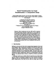
5. SOFTWARE SUPPORT
AGG software provides [6]: (1) a graphical editor for specifying graph transformation rules and (2) a customizable interpreter enabling their application through the API. Fig. 4 illustrates a UsiXML colored transformation grammar specified in AGG. Frame 1 presents the transformation catalog explorer that contains so far around 150 rules, frame 2 and 3 the colored node types and edge types available for the current catalog [18], frame 4, 5 and 6 the NAC, LHS, and RHS of the rule, respectively and the host graph on which the rule will be applied is represented in Frame 7.
Definition 8. Let TR be a transformation rule, with TR= (NAC, LHS, RHS). TR is said to be (MULTICOL)-TR iff LHS, RHS}, where g is a (MULTICOL)-Graph.
3.
COL)-TR and c ∈ {NodeColorNAC U NodeColorLHS U NodeColorRHS}\ {black}. The result of the splitting operation of the transformation rule TR1 upon the color c (TR1 [c] = TR2) is a transformation rule TR2= (NAC2, LHS2, RHS2), where:
Definition 7. Let TR be a transformation rule, with TR= (NAC,
NAC3 = NAC1 M NAC2
Definition 10. Let TR1= (NAC1, LHS1, RHS1) be a (MULTI-
The integration of the color as a new graph feature enables the introduction of the notion of colored transformation rule (i.e., (COL)-TR), which can be specialized into:
LHS, RHS). TR is said to be (MONOCOL)-TR iff LHS, RHS}, where g is a (MONOCOL)-Graph.
TR3 is a (MULTICOL)-TR
If NAC1 and NAC2 share a common black element, they are merged in order to generate the NAC3 of the resultant rule. If not, the two NACs will be aggregated in the resultant rule giving rise to two NACs. Splitting a multicolored transformation rule upon one color enables the designer to generate a monocolored rule.
4.4 Colored transformation rules
1. 2.
∃ g ∈ {NAC,
4.5 Operations over transformation rules
By analogy with the merging and splitting operations specified over graphs, we define hereafter the same operation over transformation rules. Merging two or more different colored transformation rules enables to generate multicolor rules. This operation is the cornerstone of the factoring out activity.
Even if in the context of our work the graphical concrete syntax of the transformation rules is based on the graphical formalism employed by AGG, the tool suffers from a series of shortcomings that hinders us to employ it for the colored transformation rules. In order to overcome these shortcomings an extension of the tool is proposed for implementation:
Definition 9. Let TR1 and TR2 be two (COL)-TRs, with TR1= (NAC1, LHS1, RHS1) and TR2= (NAC2, LHS2, RHS2). The result of the merging operation defined between TR1 and TR2 (TR1 M TR2 = TR3) is a transformation rule TR3= (NAC3, LHS3, RHS3), where:
• In AGG the color does not have any specific semantic meaning as it is part of the label. Thus, the extension should enable to store the color as a different feature then the label that is taken
41
that is the result of the splitting operation applied over the rule in Fig. 5 (c) upon the red color. It generates groupBox elements that embed an outputText (i.e., a label) and an imageComponent guiding the user with the available interactions to use (i.e., mouse and keyboard). If the designer wants to ensure the same functionality but enabling just the vocal interaction, the rule illustrated in Fig. 5 (b) has to be executed. It is the result of the splitting operation applied over the rule in Fig. 5 (c) upon the blue color and is used to generate vocalGroup elements. On the other hand if the designer wants to ensure a multimodal interaction the rules in Fig. 5 (a) and (b) have to be merged. The resultant rule is illustrated in Fig. 5 (c) and generates both groupBox and vocalMenu elements. The second example concerns the generation of radioButtons and/or vocalMenuItems that will be embedded in the groupBox and vocalMenu elements previously generated. Figure 6 (a) illustrates a monocolored rule that is the result of the splitting operation applied over the rule in Figure 6 (c) upon the red color.The resultant rule generates radioButton elements for each selection value of a facet of type input element. In the final UI the user will be able to select graphically between multiple options. If the designer wants to ensure the same functionality but employing the vocal interaction he will have to apply the rule illustrated in Figure 6 (b) which is the result of the splitting operation applied over the rule in Figure 6 (c) upon the blue color. On the other hand if the designer is provided with the two monocolored rules described above and has to ensure the selection of an item between multiple options by enabling user to do it graphically or vocally, the rules in Fig. 6 (a) and (b) should be merged. The resulting rule is given in Fig. 6 (c).
into consideration when applying the graph transformation rules • The color is currently defined only at the level of type graph in AGG (i.e., the meta-level in our context). Thus, while it is possible to assign colors to nodes and edges in AGG, there is an important restriction: all nodes of the same type must have the same color. This restriction does not satisfy the requirements imposed by the colored rules as the multimodal aspects of our concrete model imposes multicolored relationships whose color may change depending on the color of the source element. Consequently, the extension should enable the specification of the color at the model level, according to Table 1. • The extension should support the merging and splitting operations previously introduced.
6. CASE STUDY
Thanks to the introduction of colors, the total amount of rules to be specified by the designer is reduced. For a particular widget of a UI involving two interaction modalities (e.g., graphical and vocal), two monocolored rules had to be applied so far. These two rules can now be merged into a single multicolored rule that can be treated as follows: (1) if the designer needs to ensure both interaction modalities the multicolored rule has to be applied, (2) if the designer needs to ensure only one type of interaction (i.e., graphical or vocal) the rule has to be split upon the color assigned to the considered interaction. The flexibility of the colored rules is illustrated hereafter based on two examples that show the benefits. The first set of transformation rules are used to generate graphical and/or vocal containers. Fig. 5 (a) presents the monocolored rule NAC LHS
RHS
(a)
(b)
(c)
Figure 5. Monocolored transformation rule generating: (a) groupBox elements; (b) vocalMenu elements; (c) groupBoxes and vocalMenu elements
42
NAC
LHS
RHS
(a)
(b)
(c)
Figure 6. Monocolored transformation rule generating for each selectionValue of a facet of type select: (a) radioButtons elements; (b) vocalMenuItems elements; (c) radioButton elements and vocalMenuItem elements Reduced number of rules to be specified and applied: before introducing the notion of color the UI illustrated in Figure 7 was the result of the application of a transformation system composed of 80 rules out of which 40 were used to generate the concrete graphical elements (i.e., containers, widgets, and the relationships between). The remaining 40 rules were applied to generate their vocal counterparts. Thanks to the introduction of the colors, each pair of graphical/vocal rules can be merged into a single one, reducing thus to the half the number of rules to apply. Moreover, as many interaction types are considered, as much benefit will be gained thanks to the multicolored transformation rules. Scalability: if the need for a new modality arise (e.g., tactile modality) a new monocolored transformation rule that is duplicating the common part of its modality counterparts rules (i.e., the abstract elements represented in black) had to be developed. Thanks to the colored transformation rules the development of a new rule, and thus of the duplicating elements, is avoided. A simple integration of the new concepts assigned to the introduced modality and their mapping to the abstract elements in the already existing multicolored rule is sufficient to achieve a direct modification. As a result a new multicolored rule is obtained which can be applied in the generation of multimodal UIs considering graphical, vocal and tactile interactions.
After obtaining the concrete UI specified in UsiXML, XSL transformations are applied in order to generate the correspondent final specification (i.e., XHTML for graphical UI, VoiceXML for vocal UI and X+V for multimodal UI). Figure 7 illustrates the final multimodal system (i.e., graphical and vocal interactions) specified in X+V language and run in the Opera browser. The three groups of radio buttons enabling the user to select graphically or vocally the transmission type, the insurance type and the car class are the result of the execution of the multicolored rules specified above. More information about the tool support and demonstrations can be found at [18] where several videos recording a demonstration of the various steps required to obtain a multimodal UI for multiple contexts of use are available. The steps of the methodology have been defined in [16], which provides more technical details. In order to correctly apply the transformation sets required to perform each step of the model-driven engineering method, a dedicated software, called TransformiXML, has been developed. This tool enables the designer to select the suitable transformation system (Fig. 2) before applying the transformation rules contained in it. Further, the tool suggests the next transformation system to apply in order to achieve the next development step of the method.
7. CONCLUSION
As a result of the notion of color introduced and defined in Section 4, we have reached to the following conclusion: a multicolored transformation rule is the result of the merging operation applied over all its splitting upon each non-neutral color of the nodes. The following benefits are obtained:
The target audience that could take advantage of the benefits provided by the colored transformation rules is designers that would like to improve the performance of the development process while preserving its consistency. We did not investigate extensively the generalization of colored transformation rules but we consider that
43
our contribution could be applied in any area where factorization could be a solution for rules with a significant portion of the NAC, LHS or RHS that is duplicated.
[5]
For future steps we would like to analyze whether the introduction of color will be a conservative extension with respect to the graph grammar properties such as termination, confluence, parallel and sequential independence. Moreover, investigations will be made with respect to the feasibility of implementing an extension of the AGG tool with the features identified in Section 5.
[6]
[7] [8]
[9]
[10] [11] [12]
[13] Figure 7. Final UI enabling graphical and vocal interaction [14]
8. ACKNOWLEDGMENTS
We gratefully acknowledge the support of the SIMILAR network of excellence (http://www.similar.cc), the European research task force creating human-machine interfaces similar to human-human communication of the European Sixth Framework Programme (FP6-2002-IST1-507609). The authors would like to greatly thank the anonymous reviewers for their constructive comments.
[15]
[16]
9. REFERENCES
[1] Agrawal, A. 2003. Metamodel Based Model Transformation Language. In Proc. of ACM Int. Conf. on Object-Oriented Programming Systems, Languages and Applications OOPSLA’2003 (Anaheim, Oct. 26-30, 2003). ACM Press, New York, 386–387. [2] Calvary, G., Coutaz, J., Thevenin, D., Limbourg, Q., Bouillon, L., and Vanderdonckt, J. 2003. A Unifying Reference Framework for Multi-Target User Interfaces. Interacting with Computers 15, 3 (June 2003), 289–308. [3] Czarnecki, K. and Antkiewicz, M. 2005. Mapping features to models: A template approach based on superimposed variants. In Proc. of Int. Conf. on Generative Programming and Component Engineering GPCE’2005. Lecture Notes in Computer Science, Vol. 3676. Springer, Berlin, 422–437. [4] Czarnecki, K. and Helsen, S. 2006. Feature-Based Survey of
[17]
[18]
44
Model Transformation Approaches. IBM Systems Journal 45, 3 (2006), 621–645. Czarnecki, K. and Pietroszek, K. 2006. Verifying FeatureBased Model Templates Against Well-Formedness OCL Constraints. In Proc. of 5th ACM SIGSOFT/SIGPLAN Int. Conf. on Generative Programming and Component Engineering GPCE’06. ACM Press, New York, 211–220. Ehrig, H., Engels, G., Kreowski, H-J., and Rozenberg, G. (eds.). 1999. Handbook of Graph Grammars and Computing by Graph Transformation, Application, Languages and Tools, Vol. 2, Chapter 3, Section 3.6.2 The Graph Transformation Language AGG. World Scientific, Singapore. Jensen, K. 1998. A brief introduction to colored Petri nets. In Proceedings of Workshop on the Applicability of Formal Models (Aarhus, 2 June 1998), 55–58. Limbourg, Q. and Vanderdonckt, J. 2004. UsiXML: A User Interface Description Language Supporting Multiple Levels of Independence. In Matera, M. (Eds.), Engineering Advanced Web Applications, Rinton Press, Paramus, 325–338. Medina, J-L., Chessa, S., and Front, A. 2007. A Survey of Model Driven Engineering Tools for User Interface Design. In Proc. of 6th Int. workshop on Task Models and Diagrams TAMODIA’2007 (Nov. 7-9, 2007). Springer, Berlin, 84–97. Mellor, S.J. and Clark, A.J. 2003. Introduction to Model Driven-Development. IEEE Software 20, 5 (2003), 14-18. Mellor, S.J., Kendall, S., Uhl, A., and Weise, D. 2004. MDA Distilled – Principles of Model-Driven Architecture. Addison-Wesley, New York. Mens, T. and Van Gorp, P. 2006. A Taxonomy of Model Transformation. In: Proc. of International Workshop on Graph and Model Transformation GraMoT’2005, Electronic Notes in Theoretical Computer Science, 152 (2005) 125– 142. Nigay, L. and Coutaz, J. 2005. A Generic Platform for Addressing the Multimodal Challenge. In Proc. of the ACM Conf. on Human Factors in Computing Systems CHI’95 (Denver, 1995). ACM Press, New York, 98–105. Schaffer, R. 2007. A Survey on Transformation Tools for Model Based User Interface Development. In J. Jacko (Ed.): Human-Computer Interaction, Part I, Proc. of HCI’International 2007. LNCS 4550, Springer, Berlin, 1178–1187. Schlee, M. and Vanderdonckt, J. 2004. Generative Programming of Graphical User Interfaces. In Proc. of 7th Int. Working Conf. on Advanced Visual Interfaces AVI’2004 (Gallipoli, May 25-28, 2004). ACM Press, New York, 403-406. Stanciulescu, A., Limbourg, Q., Vanderdonckt, J., and Michotte, B. 2005. A Transformational Approach for Multimodal Web User Interfaces based on UsiXML. In Proc. of 7th Int. Conf. on Multimodal Interfaces ICMI'2005 (Trento, 4-6 October, 2005). ACM Press, New York, 259– 266. Vanderdonckt, J., Coutaz, J., Calvary, G., and Stanciulescu, A. 2007. Multimodality for Plastic UI: Models, Methods, and Principles. In D. Tzovaras (ed.), “Multimodal UIs: from signals to interaction”, Chap. 3. Lecture Notes in Electrical Engineering. Springer-Verlag, Berlin, 79– 105. http://www.usixml.org