EPCs describe the flow of control of business processes as a chain ... concerns all aspects of organizational activities, less and less manual work is ..... of the form v1 x v2 or v1 x c, where v1, v2 are either attributes or resource ..... pattern has two transitions and an intermediate place depicting the two steps .... output (b1,b2);.
Colored Petri Nets to Verify Extended Event-Driven Process Chains Kees van Hee, Olivia Oanea, and Natalia Sidorova Department of Mathematics and Computer Science, Eindhoven University of Technology, P.O. Box 513, 5600 MB Eindhoven, The Netherlands {k.m.v.hee, o.i.oanea, n.sidorova}@tue.nl
Abstract. Business processes are becoming more and more complex and at the same time their correctness is becoming a critical issue: The costs of errors in business information systems are growing due to the growing scale of their application and the growing degree of automation. In this paper we consider Extended Event-driven Process Chains (eEPCs), a language which is widely used for modeling business processes, documenting industrial reference models and designing workflows. We describe how to translate eEPCs into timed colored Petri nets in order to verify processes given by eEPCs with the CPN Tools. Keywords: Extended EPCs, semantics, verification, colored Petri nets.
1
Introduction
Event-driven Process Chains (EPC) [15,17] is a popular language for modeling business processes, documenting industrial reference models and designing workflows. EPCs describe the flow of control of business processes as a chain of functions, events, and logical connectors. Functions represent activities in a business process. An event expresses a precondition (trigger) for a function or a postcondition that signals the termination of a function. Logical connectors and, or, and xor are used according to their names to build the control flow of a process in a natural way. EPCs extended with data, resources, time and probabilities, called extended EPCs (eEPCs) [17], are intensively used in commercial tools like Architecture ¯¯ of Integrated Information Systems (ARIS) [15] and SAP R/3 [11]. These tools ¯ ¯ support modeling and simulation of organizational processes with eEPCs, and they are widely used in such branches of industry and consultancy as banks, insurance companies, transportation. The complexity of business processes in these branches is growing throughout the years. Due to informatisation, which concerns all aspects of organizational activities, less and less manual work is involved into the supervision of business processes. This accelerates processes significantly, but also puts higher requirements to the correctness of process specifications, since an error in a process design would demonstrate itself in an automated system too late, when it would already cause a snowball effect. R. Meersman and Z. Tari (Eds.): CoopIS/DOA/ODBASE 2005, LNCS 3760, pp. 183–201, 2005. c Springer-Verlag Berlin Heidelberg 2005 �
184
K. van Hee, O. Oanea, and N. Sidorova
We choose to use an available tool for modeling, simulation and analysis of the constructed model, e.g. model checking which covers the whole system behavior, and we provide a translation from eEPCs to the input language of this tool. Petri nets are appropriate for modeling EPCs since all EPC elements can be translated to places and transitions of Petri nets in a natural way (see e.g. [1,7,13]). Extended EPCs have such additional features as data, time and probabilities. Therefore timed colored Petri nets (TCPNs) [10] are a natural choice for modeling eEPCs. CPN Tools [3] provides modeling, simulation, and model checking options for TCPNs and thus satisfies our requirements. In this paper, we provide a formal definition for eEPCs and present their semantics in terms of a transition system. We provide a translation from eEPCs to TCPNs and describe how we can analyze the behavior of an eEPC with the CPN Tools. We conclude by comparing our method to other approaches for formalizing the syntax and the semantics of EPCs. The rest of the paper is organized as follows. In Section 2 we describe the syntax of eEPCs. In Section 3 we provide the semantics of eEPCs as used in practice. Section 4 gives a translation from eEPCs to timed colored Petri nets and discusses some verification issues. In Section 5 we give an account of related work and discuss some future work.
2
Syntax of Extended Event-Driven Process Chains
In this section, we give a brief description of the syntax of eEPCs taking into account requirements given in [15] as well as the ones imposed by practice. We use ARIS [6,9,15,17] as a reference point of our study. However, this approach can be applied to other tools supporting eEPCs, since they are based on the same concepts. ARIS offers a conceptual framework for describing companies, their organizational structure, processes and resources (material as well as human). In addition to process modelling, ARIS offers the possibility to analyze process performance based on simulation. In order to structure process modelling and to show different angles of an organization, ARIS distinguishes five main views: Data view uses the entity-relationship models (ERM) to design data models: entities (e.g. data objects of the environment that are processed by the system), their attributes and relationships between entities; Function view describes functions as tasks performed on objects to support different company goals; it includes descriptions of procedures, processes, subfunctions and elementary functions; Organization view models the relations between company units and the classification of these units in the organizational hierarchy; Product/service view describes the products and services produced by the company as a result of human act or technical procedures; Control view integrates the previously mentioned views and defines the dynamic, behavioral aspects. The control flow of a process is described with
Colored Petri Nets to Verify Extended Event-Driven Process Chains
185
an EPC extended with the description of the resources and data involved in the process, and timed and probabilistic aspects of the behavior. The control view is essential for process verification, so we concentrate our study on this view. In what follows, we define generic EPCs and extend them to eEPCs as they are presented in the control view of ARIS. 2.1
Syntax of EPCs
First we give some basic definitions from algebra and the graph theory we need here. – Let S be a set. |S| denotes the number of elements in S. B denotes the boolean set, N the set of natural numbers, Z the set of integers, R the set of real numbers and R+ the set of positive real numbers. – A multiset (bag) over S is a mapping m : S → N. The set of all multisets over S is NS . We use + and − for the sum and the difference of two multisets and =, , ≤, ≥ for comparisons of multisets. ∅ denotes the empty multiset and ∈ denotes element inclusion. We write m = 2‘a for a multiset m with m(a) = 2 and m(x) = 0 for any x ∈ S − {a}. – Let R ⊆ S × S be a binary relation over a set S. R−1 denotes the converse relation of R, R+ denotes the transitive closure of R, R∗ denotes the transitive reflexive closure of R and (R ∪ R−1 )∗ is the symmetric, reflexive and transitive closure of R. – A directed graph is a tuple G = (N, A), where N is a set of nodes and A ⊆ N × N is a set of arcs. Every arc a ∈ A is a pair (n1 , n2 ) ∈ N × N consisting of the input node n1 and the output node n2 . – A path σ of length m in a graph G = (N, A) is a finite sequence of nodes σ = n0 n1 . . . nm (ni ∈ N for i = 0, . . . , m) such that each pair (vj , vj+1 ) ∈ A (j = 0, . . . , m − 1) is an arc. We denote the length of a path by |σ|(= m). σ is an empty path if |σ| = 0. We denote the set of all finite, possibly empty, paths by N ∗ and the set of finite non-empty paths by N + . A path σ is a prefix of a path γ if there is a path σ � with γ = σσ � . – A graph G = (N, A) is weakly connected if for every two nodes n1 , n2 ∈ N , (n1 , n2 ) ∈ (A ∪ A−1 )∗ . – We denote the set of output nodes of n ∈ N as n• , i.e. n• = {n� |(n, n� ) ∈ A}. Similarly, • n = {n� |(n� , n) ∈ A} is the�set of input nodes of � n ∈ N . Given a set of nodes X ⊆ N , we define • X = n∈X • n and X • = n∈X n• . in – We denote the set of ingoing arcs of a node n ∈ N as Ain n , i.e. An = out {(n, x)|x ∈ n• } and the set of outgoing arcs of n as Aout , i.e. A = n n in is singleton, a denotes the ingoing arc of {(x, n)|x ∈ n• }. In case Ain n n the node n. Similarly, if Aout is singleton, aout denotes the outgoing arc of n n the node n. Now we can give a definition of a generic EPC. Definition 1 (EPCs). An event-driven process chain (EPC) is defined by a weakly connected directed graph G = (N, A) that satisfies the following properties:
186
K. van Hee, O. Oanea, and N. Sidorova
1. The set N of nodes is the union of three pairwise disjoint sets E, F and C, where – E is the set of events. E = Es ∪ Ef ∪ Ei , where Es , Ef and Ei are pairwise disjoint sets of start events, final events, and internal events respectively, with |Es | ≥ 1 and |Ef | ≥ 1; – F �= ∅ is a set of functions; – C is a set of connectors of types xor, or, and, i.e. C = Cxor ∪Cor ∪Cand , where Cxor , Cor and Cand are disjoint sets. Furthermore, each of these sets is partitioned into two sets representing split and join connectors: Cxor = Cxs ∪ Cxj , Cor = Cos ∪ Coj and Cand = Cas ∪ Caj , and Cs stands for set of split connectors, and Cj stands for the set of join connectors; 2. Every element from the set A of arcs connects two different nodes. Moreover, – • es = ∅ and e•f = ∅, for each es ∈ Es and ef ∈ Ef ; – |n• | = 1 for each n ∈ F ∪ Ei ∪ Es , and |• n| = 1 for each n ∈ F ∪ Ei ∪ Ef ; – each split connector c ∈ Cs satisfies |• c| = 1 and |c• | > 1; similarly each join connector c ∈ Cj satisfies |• c| > 1 and |c• | = 1; 3. Each node is on a path from a start event to a final event, i.e. for any n ∈ N , there is a path σ from some es ∈ Es to some ef ∈ Ef , such that n ∈ σ; 4. Functions and events alternate along the control flow, i.e. each path starting in an event e ∈ E − Ef and ending in an event ef ∈ Ef has a prefix of the form eσc f , where σc ∈ C ∗ and f ∈ F . Similarly, for each path σ starting in a function f ∈ F and ending in an event ef ∈ Ef there is a prefix f σc e, where σc ∈ C ∗ and e ∈ E − Es ; 5. Events do not precede the xor and the or split, i.e. ∀c ∈ Cxs ∪Cos : • c∩E = ∅; 6. There is no cycle that consists of connectors only, i.e. for any path σ = v0 v1 . . . vn ∈ C + : n ≥ 2 : v0 �= vn . 2.2
Syntax of Extended EPCs
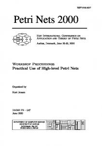
The control view of an eEPC has an EPC as a skeleton. Data attributes, resources, time and probabilities are linked to different EPC elements to form an extended EPC. Functions represent activities that may take time, may require access to diverse resources and may perform operations on some data or resources. Functions that perform operations on data attributes are annotated with expressions denoting the operation performed (see for example Figure 1(a)). Personnel, material or information resources can be used to execute functions. We call these objects capacity resources, since they are characterized by minimum and maximum capacities to run the process. Functions are annotated with a nonnegative integer or real constant denoting the number of resources required, produced or consumed. In Figure 1(b), function finish products produces 1000 items of resource Item 1 with the capacity domain [100, 5000] and consumes 500 items of resource Item 2. Furthermore, functions can be either timed, i.e. they may have a duration, or immediate, i.e they take zero time. The duration of each timed function is described by a probability distribution.
Colored Petri Nets to Verify Extended Event-Driven Process Chains
Order received
Event
r2min=100 r2max =5000 r2 =1000
r1min=100 r1max =5000 r1 =1000
Type(a)=Integer a=5000 Data Attribute
187
Function
Item 1
a := a + 450
produces 1000
Finish products
consumes 500
Item 2
XOR XOR
a < 7500 Condition event 1
Item 1
a >= 7500 Data Attribute
Condition event 2
Products are sent to warehouse
Products are sent for sale Item 2
(a) Condition events on a data attribute
r1 >= r2
r1 < r2 (b) Condition events on resources
Fig. 1. Condition events on data attributes and resources
Events define either conditions on data attributes or resource capacities, or triggers from elements outside the process. Processes are instantiated at start events. Start events may be grouped in start event sets1 that contain events which are synchronized, i.e. a process is started at the same time at all the events of the respective set. A probability distribution is assigned to each start event set, denoting the frequency with which process instances are created for the events in the respective set. Conditions (boolean expressions) on data attributes or on resources determine the terms of the respective event. An event that follows an or split or an xor split connector and is determined by a condition is called a condition event. Condition events may have attributes or capacity resources connected to them and conditions are specified as: – conditions on one operand that have a constant value of the same type as the attribute or the capacity value of a resource as comparison criterion. Figure 1(a) shows two condition events annotated with boolean expressions on a data attribute; – conditions on two operands that compare two attribute values or the capacity values of two resources. In Figure 1(b), the condition events products are sent to warehouse and products are sent for sale are annotated with the boolean expressions r1 < r2 and r1 ≥ r2 on the resources Item 1 and Item 2. The rest of events are used to model triggers from outside the process and they have a probability value assigned. This value is used during the simulation to determine whether the execution stops or continues at the respective event. Probability values for events following and split connectors are 1 since the execution cannot stop at events following such a connector. The sum of probability 1
In ARIS, event diagrams are used to represent start event sets.
188
K. van Hee, O. Oanea, and N. Sidorova
values for events following xor split connectors is exactly 1 as the execution can continue only on one outgoing branch. Furthermore, the sum of probability values for events following or split connectors is greater than 1 as the execution can continue on one or more outgoing branches. Or join connectors may also contain some timeout information, called synchronization timeout. We give a formal definition of eEPCs as they are used in ARIS Toolset. Definition 2 (eEPC). An extended event-driven process chain (eEPC) is a tuple Ge = (G, A, R, Type, Expr, P DF, Pr), where – G is an underlying EPC. � – A is a set of data attributes. We write A = f ∈F Af for a partition of the set of data attributes w.r.t. the function performing operations on them. – R is a set of capacity resources. We partition the set of � resources according to the function performing operations on them: R = f ∈F Rf such that these sets are not disjoint (several functions can perform operations on the same resource). Moreover, we consider a partition of the set of resources used by a function f into used, produced and consumed resources, i.e. Rf = Ruf ∪ Rpf ∪ Rcf such that these sets are disjoint (a function can perform just one type of operation on a resource). – Type maps each attribute to one of the types Text, Enum, B, Z, or R and each capacity resource r to a real or integer subtype [rmin , rmax ], where rmin and rmax are the minimum and maximum capacities of resource r. � – Expr = Exprb ∪ x∈R∪A Exprx maps condition events and functions into expressions on the attributes or capacity resources linked to them as follows: • Ec denotes the set of condition events, i.e. events folowing or and xor split connectors that have conditions on data attributes or resources. Every condition event e ∈ Ec is mapped to a boolean expression Exprb (e) of the form v1 x v2 or v1 x c, where v1 , v2 are either attributes or resource capacities, c is a constant so that Type(v1 ) = Type(v2 ) = Type(c) and x is the comparison operator compatible with the types used. • every function f performing an operation on an attribute a is mapped to an expression on a, namely Expra (f ), having the form a := c, where c is a constant value with Type(a) = Type(c), or a := a x c, with Type(a) = Z or Type(a) = R, constant c with Type(a) = Type(c) and x∈ {+, −, ∗}. • Exprr (f ) maps function f using, producing or consuming a resource r ∈ Rf to constant cfr ∈ Type(r), denoting the quantity of resources used, consumed or produced. – Ft denotes the timed functions, and Cs denotes the set of or join connectors with synchronization timeout. We � consider the set of start events Es partitioned into start event sets, i.e. d∈Is Esd , for some index set Is .
Colored Petri Nets to Verify Extended Event-Driven Process Chains
189
Trade executed
Type(tu)= {manual, electronic} Monitor receipt of trade tu:=manual Trade use confirmation and administration
V XOR
XOR tu = manual Received trade confirmation (manual)
tu = manual
tu = electronic
tu = electronic
Trade Administrated (manual use)
Trade Administrated (electronic use)
Received trade confirmation (electronic)
Trade use
V
V
Match BLIM
Visual trade check
0.40
Trade checked
XOR
BLIM Match
XOR
0.60
No BLIM match
Start release process
Reject BLIM
Release process started
BLIM rejected
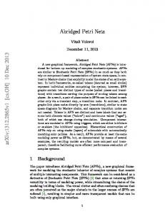
Fig. 2. Trade matching eEPC
� P DF = k∈(Ft ∪Cs ∪Is ) pdfk denotes a family of continuous or discrete probability distributions2 for the duration of timed functions, for the synchronization timeouts of synchronized or join connectors, and for the delays of start event sets. – Pr : E − Es − Ec → [0, 1] which maps events to their probability values such that:� c • e∈E c Pr(e) = 1, for each set of events E following an xor split connector c ∈ Cxs that have probability values; 2
In this paper, a probability distribution pdf ∈ P DF refers to a probability distribution function (we do not mention the word function in order to avoid confusion with functions as nodes of eEPCs).
190
K. van Hee, O. Oanea, and N. Sidorova
•
�
Pr(e) ≥ 1, for each set of events E c that have probability values and follow an or split connector c ∈ Cos ; • Pr(e) = 1 for each e ∈ Cas • . e∈E c
Figure 2 shows an eEPC modeling a part of a trade matching process taking place in a company. The process checks the timely receipt of a confirmation, administrates the trade internally and matches the confirmation against the internal data before the release process can be started. The process starts with the event trade executed (deal made) that triggers the function monitor receipt of trade confirmation and administration. This results in a change of the data attribute trade use. The execution is then split into two parallel threads, which is modeled by an and split. The left thread models the check whether the confirmation of the trade has been received electronically or manually by means of an xor split and two condition events: Received trade confirmation (manual) and Received trade confirmation (electronic) that are linked to a data attribute Trade use. The second thread models the check whether the trade is administered for manual or electronic use by means of conditions on the attribute trade use. The two and join connectors make sure that the matching process continues either manually or electronically. The visual (manual) check is performed by the function visual trade check and results in the event trade checked. The result of the electronic matching of the internal information with BLIM messages has 40% probability to succeed. In case the trade has been matched either manually or electronically, which is modeled by an xor join, the process is released by start release process. If the data registered internally does not match the information contained in the BLIM message, the message is rejected.
3
Semantics of eEPCs
We introduce first the notions of a process folder and a state of an eEPC necessary to define the semantics of eEPCs. A process folder is an object that resides at a node (function or start event) or at an arc. Furthermore, it carries a folder number and a timestamp denoting the value of the timer associated to the folder. Timestamps are either nonnegative numbers indicating the delay after which the folder may be used, or ⊥, denoting that the timer of the process folder is off and the folder can be used directly. A state of an eEPC is defined by a multiset of process folders together with a valuation of data attributes and capacity resources. For the rest of the paper, we consider the discrete time domain N⊥ = N∪{⊥} and discrete probability distributions for durations. We denote the domain of a discrete probability distribution pdf ∈ P DF by Dom(pdf ) ⊆ N. The same approach can be applied for continuous time and continuous probability distributions. We consider process folder numbers to take values from N. Formally: Definition 3. Let Ge = (G, A, R, Type, Expr, P DF, Pr) be an eEPC. A process folder is a tuple p = (n, (i, t)) where n ∈ Es ∪ F ∪ A is a start event,
Colored Petri Nets to Verify Extended Event-Driven Process Chains
191
a function or an arc, i ∈ N is a process folder number and t ∈ N⊥ is a timestamp. A state of Ge is a tuple s = (m, Val), where m is a multiset of process folders, i.e. m : ((F ∪ A ∪ Es ) × (N × N)) → N, and Val is a valuation function that maps every resource r ∈ R into some value Val(r) ∈ Type(r) and every data attribute a ∈ A to some value Val(a) ∈ Type(a). We denote the timestamp of a process folder p by pt . We will say that a process folder has its timer off when pt =⊥ and its timer on when pt ≥ 0. We call a process folder with the timer on active if it has the timestamp 0. If pt > 0, the process folder is waiting to become active. Every start event of a start event set has initially an active process folder with the index of the start event set as its folder number. The initial state is thus s0 = (m0 , Val0 ) and contains one active process folder on every start event so that for every start event set (es , (i, 0)) ∈ m0 for all es ∈ Esi , and every resource and data attribute has an initial value according to the specification. Probability distributions are used in eEPCs to model the behavior of the environment or to describe nondeterminism in the system (when decisions need to be made), and for performance analysis. Since all events that have Pr(e) > 0 can occur and the errors in a model (eEPC) having probabilistic events can thus be detected on the model without probabilities, we do not take probabilities further into consideration, as they are irrelevant to our verification purposes. In order to express nondeterminism without probabilities, we extend the mapping Expr to non-condition events and set Exprb (e) = true, for every event e ∈ (Cos ∪ Cxs )• − Ec , and subsequently extend the set of condition events to all events following an or and xor split connector, i.e. Ec = (Cos ∪ Cxs )• . Let eval be the evaluation function for expressions, such that: – eval(Exprb (e), Val) ∈ B is the evaluation function of the boolean expression of condition events e ∈ Ec in the valuation Val. – eval(Expra (f ), Val) ∈ Type(a) is the evaluation function of the expression Expra (f ) on some data attribute a ∈ Af in the valuation Val that computes a new value for a from the right hand side expression of Expra (f ). For any r ∈ R, we introduce a variable r such that Val0 (r) = Val0 (r) in order to keep track of resources that would be modified by several functions. We denote the set of variables newly introduced by R. We describe the semantics of an eEPC by means of a transition relation between states as follows: Definition 4. Let Ge = (G, A, R, Type, Expr, P DF, Pr) be an eEPC. The semantics of an eEPC is given by a transition system T S = (Σ, s0 , →), where Σ is the set of states of Ge , s0 is the initial state, and →⊆ Σ × Σ is a transition relation described by the rules (a) − (j) below. Let s = (m, Val) and s� = (m� , Val� ) be two states in Σ.
192
K. van Hee, O. Oanea, and N. Sidorova
(a) start event set rule Let Esd be a start event set such that there is a process folder on each of its start events and all the folders have the same folder number and are active. Then a step can be taken that results in removing all the folders on the events of Esd and producing a process folder on each of the outgoing arcs of Esd which have the same folder number as the original process folders and their timers are set to off. Furthermore, a new process folder is generated on each event of Esd ; all these new process folders have the same newly generated folder number and the same timestamp which is drawn from the probability distribution of the start event set. d � Formally, � if (e, (i, 0)) ∈ m for s , d ∈ Is and �all e ∈ E � i ∈ N, then s → s , with � out m = m− e∈Esd (e, (i, 0))+ e∈Esd (ae , (i, ⊥))+ e∈Esd (e, (i + |Is |, t)), for some t ∈ Dom(pdfd ). (b) event rule Let ain e be the incoming arc for an event e such that there is a in process folder on ain e . Then, the process folder can be removed from ae and out in placed on the outgoing arc of the event ae . Formally, if (ae , (i, ⊥)) ∈ m for some i ∈ N and e ∈ E − Es − Ec − Ef , then (m, Val) → (m� , Val) with in m� = m + (aout e , (i, ⊥)) − (ae , (i, ⊥)). in (c) function rule Let af be the incoming arc of a function f such that there is a process folder on ain f . The function rule consists of two steps: – if the resources may be used, consumed or produced, the process folder is removed from the incoming arc of the function, and a new process folder having the same folder number as the original folder and a timestamp from the time distribution interval of the function is placed on the function, and resources are consumed. Formally, if (ain f , (i, ⊥)) ∈ m, for some f ∈ F and i ∈ N, Val(r) − Exprr (f ) ≤ rmin for all r ∈ Ruf ∪ Rcf , Val(r) + Exprr (f ) ≤ rmax for all r ∈ Rpf , then s → s� , where s� = (m� , Val� ), m� = m − (ain f , (i, ⊥)) + (f, (i, t)), where t = 0 if t ∈ F − Ft and t ∈ Dom(pdff ) if t ∈ Ft , Val� (r) = Val(r) − Exprr (f ) for all r ∈ Rcf ∪ Ruf , Val� (r) = Val(r) − Exprr (f ) for all r ∈ Rcf , Val� (r) = Val(r) + Exprr (f ) for all r ∈ Rpf c p and Val� (x) = Val(x) for all x ∈ (R ∪ R ∪ A) − (Rcf ∪ Ruf ∪ Rf ∪ Rf ). – Let f be a function such that there is an active process folder on it. Then, the active process folder is removed from the function, and a new process folder is produced on the outgoing arc of the function; this new folder has the same folder number as the removed one and the timer off; attributes are evaluated and resources are produced or released. Formally, if (f, (i, 0)) ∈ m, for some f ∈ F and i ∈ N, then s → s� , with � s� = (m� , Val� ), m� = m − (f, (i, 0)) + (aout f , (i, ⊥)), where Val (a) = � eval(Expra (f ), Val) for all a ∈ Af , Val (r) = Val(r) + Exprr (f ) for all resources r ∈ Rpf ∪ Ruf produced or used, and Val� (x) = Val(x) for all x ∈ (R ∪ R ∪ A) − (Af ∪ Rpf ∪ Ruf ). (d) and split rule Let ain c be the ingoing arc of an and split connector c such that there is a process folder on ain c . The rule results in removing the process folder from ain and placing a process folder on each outgoing arc of the and c split connector such that all new process folders have the same folder number
Colored Petri Nets to Verify Extended Event-Driven Process Chains
193
as the removed folder. Formally, if (ain for some i ∈ N and c , (i, ⊥)) ∈ m, � c ∈ Cas , then s → s� with s� = (m, Val) and m� = m + a� ∈Aout (a� , (i, ⊥)) − c (ain c , (i, ⊥)). (e) xor split rule Let ain c be the incoming arc of an xor split connector c such that there is a process folder on ain c . Then the process folder is removed from the arc ain c and – if the xor split leads to a non-final condition event whose boolean expression is evaluated to true, a process folder with the same number as the removed one is placed on the outgoing arc of the event; – if there is an outgoing arc of the xor split leading to a final condition event whose boolean expression is evaluated to true or to another connector, then a process folder with the same number as the removed one is placed on the respective arc. � Formally, if (ain c , (i, ⊥)) ∈ m, for some i ∈ N and c ∈ Cxs , then s → s , with � � � � in s = (m , Val) and m = m + (a , (i, ⊥)) − (ac , (i, ⊥)), where
– a� = aout if eval(Exprb (e), Val) = true for some event e ∈ c• − Ef , or e – a� = (c, e), if eval(Exprb (e), Val) = true for some final event e ∈ c• ∩ Ef , or – a� = (c, c� ) for some c� ∈ C. (f ) or split rule Let ain c be the ingoing arc of an or split connector c such that there is a process folder on ain c . The rule results in removing this folder from ain and placing a process folder with the same folder number on at least one c of the outgoing arcs of the non-final condition events that have a true boolean expression or the outgoing arcs of the or split connector leading to final condition events with boolean expression evaluated to true or to connectors. � Formally, if (ain c , (i, ⊥)) ∈ m, for some i ∈ N and � c ∈ Cos , then s → s , � � � in with s = (m , Val) and m = m − (ac , (i, ⊥)) + a∈A� ∪A�� (a, (i, ⊥)), where b • �� A� ⊆ {aout e |e ∈ c ∩ (Ec − Ef ) ∧ eval(Expr (e), Val) = true} and A ⊆ b out • {(c, e) ∈ Ac |e ∈ c ∩ (Ec ∩ Ef ) ∧ eval(Expr (e), Val) = true} ∪ {(c, c� ) ∈ � �� Aout c |c ∈ C} and A ∩ A �= ∅. in (g) and join rule Let Ac be the set of all incoming arcs of an and join connector c. If all arcs of Ain c have process folders with the same folder number, the rule can be applied resulting in the removal of these process folders from Ain c , and the production of a process folder with the same process folder number as the original folders on the outgoing arc of the connector. Formally, if there is a c ∈ Caj such that (a, (i, ⊥)) ∈ m, for all arcs a ∈ Ain i ∈ N, then s → s� with s� = (m� , Val), and c and some � � out m = m + (ac , (i, ⊥)) − a∈Ain (a, (i, ⊥)). c
(h) xor join rule Let a be an incoming arc of an xor join connector such that there is a process folder on a. Then, the folder is removed from a and placed on the outgoing arc of the connector. Formally, if (a, (i, ⊥)) ∈ m � � � for some i ∈ N, c ∈ Cxj and a ∈ Ain c , then s → s with s = (m , Val), � out in m = m + (ac , (i, ⊥)) − (ac , (i, ⊥)).
194
K. van Hee, O. Oanea, and N. Sidorova
(i) or join rule Let A� be the set of incoming arcs of an or join connector that have process folders with timers off and the same folder number. The rule consists of one or more steps (depending on whether the connector has a synchronization time or not): – (or join unsynchronized) In case the or connector does not have a synchronization timeout, the rule results in removing all the folders with timers off and the same folder number on A� and producing a process folder with the same folder number as the original folders and the timer off on the outgoing arc of the connector. Formally, if there is a c ∈ Coj − Cs such that A� = {a ∈ Ain c |(a, (i, ⊥)) ∈ m} �= ∅, for some i�∈ N, then s → s� with s� = (m� , Val) and m� = m + (aout c , (i, ⊥)) − � (a , (i, ⊥)). a� ∈A� – (or join synchronized waiting) Let A�� be a set of incoming arcs of a synchronized or join connector that have waiting process folders on them with the same folder numbers as the folders on A� . The rule results in removing the process folders with timers off and the same folder number on A� and producing new process folders on A� having the same folder number as the removed ones and a timestamp that is either the synchronization time of the or connector in case A�� is empty or the timestamp of the folders in A�� if A�� is non-empty. Formally, let A� = {a = (x, c) ∈ A|x ∈ �� �� N ∧ (a, (i, ⊥)) ∈ m} �= ∅ and A�� = {a ∈ Ain c |(a, (i, t )) ∈ m ∧ t > 0} �� � for some i ∈ N and c ∈ Cs . If A = ∅ then let t = t be the timestamp of the process folders p = (a, (i, t)) ∈ m, where a ∈ A�� , otherwise let � t ∈ Dom(pdff ). Then, s → s� with s� = (m� , Val) and � m� = m + a� ∈A� (a� , (i, t� )) − a� ∈A� (a� , (i, ⊥)). – (or join synchronized firing) Let A�� be the set of incoming arcs of an or connector that have an active process folder on them and all these folders on A�� have the same folder number. Then these process folders are removed from A�� and a new process folder is produced on the outgoing arc of the connector, so that it has the same folder number as the original folders and the timer off. Formally, if for some c ∈ Coj − Cs and i ∈ N, � � � A�� = {a ∈ Ain c |(a, (i, 0)) ∈ �m} �= ∅, �then s → s with s = (m , Val) and � out m = m + (ac , (i, ⊥)) − a� ∈A�� (a , (i, 0)). (j) time step rule This rule has the lowest priority, i.e. the rule is applied if no other rule can be applied. Time passage is applied when all process folders with timers on in a state are waiting (have a strictly positive timestamp) and results in decreasing the timestamp of all process folders of the state by the minimal timestamp of the folders with timers on. Formally, if P � = {p ∈ m|pt > 0} �= ∅ and st = min{pt |p ∈ P � } > 0 and there is no � � � other state� s�� �= s� such that s → s�� , then � s → s , with s = (m , Val), where m� = m + (x,(i,t))∈P � (x, (i, t − st )) − p∈P � p. Remark 5 (Uniqueness of newly generated folder numbers). Folder numbers generated at some start event set Esd (d ∈ Is ) have the form d + k · n, where n = |Is | and k ∈ N. Therefore, all folder numbers produced at Esd are equal modulo the
Colored Petri Nets to Verify Extended Event-Driven Process Chains
195
index number of the start event set, i.e. d. As a result, all process folder numbers that are generated are unique. Remark 6 (Time progress). The time step rule decreases the timestamp of a waiting process folder until it becomes active (its timer expires). Note that all other steps have the same higher priority than the time progress and their semantics is interleaving. The time progress problem reduces to the situation where no other rule can be applied or to the situation where there is an infinite sequence of (timeless) rules that can be applied. We therefore assume that there is a finite number of process folder numbers such that the states contain a finite number of process folders with the same folder number.
4
Verification of eEPCs Using CPN Tools
To verify the correctness of eEPCs, we use the CPN Tools [3] which are based on colored Petri nets [10] as modeling and analysis language. (Timed) Colored Petri nets (TCPNs) combine the expressive power of classical PNs, which are suitable for modeling the logical behavior of a control flow, with the modeling of data and time by means of timed color sets and a global clock. A state of a TCPN is called a marking and represents the distribution of (timed) colored tokens on places. Tokens belonging to a timed color set have a timestamp and they can only be used if the value of the timestamp is less than the value of the global clock. Let Ge be an arbitrary eEPC and T S = (Σ, s0 , →) the transition system describing the semantics of Ge . We denote the timed integer color corresponding to the set of process folders numbers by PF, and for each capacity resource and data attribute, we define a place having the corresponding untimed color type. The locations at which process folders can reside correspond to TCPN places having type PF and local steps in TCPNs are depicted by transitions. A step that can be taken in the eEPC corresponds to a transition firing, given preconditions and postconditions expressed as expressions on arcs or guards (boolean expressions) on transitions. The global clock (model time) advances the timestamps of all timed tokens with the smallest amount of time needed to make at least one token active, which corresponds to the time step rule in eEPCs in which timers decrease their values. Token delays are positioned on transitions or on outgoing arcs of transitions. 4.1
Transformation of eEPCs into TCPNs
For mapping of eEPCs into TCPNs, we first identify generic eEPC patterns and provide their translation into TCPN patterns, and then we show how the obtained TCPN patterns can be fused together to form a TCPN. We define eEPC patterns taking into account the rules of the semantics given in Section 3 (except for the time step rule), covering all patterns that would allow us to build an arbitrary eEPC. An eEPC pattern consists of incoming and outgoing arc(s) and other elements necessary for the rule to occur.
196
K. van Hee, O. Oanea, and N. Sidorova
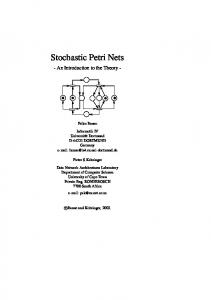
Figures 3(a-i) and 4 show instances of these patterns having the incoming (outgoing) arcs dotted and their corresponding TCPN pattern. In what follows we describe these transformations in more detail. Start event set pattern. Let Esd be a start event set for some d ∈ Is and let n = |Esd |. The corresponding TCPN pattern is represented by a place which is initially marked with a token d@0 (with timestamp 0) and where a newly generated token with a delay is deposited; a transition that generates a new token, adds a delay to its timestamp and puts the token from the former place on the places corresponding start events of the start event set. Figure 3(a) shows the eEPC pattern and the TCPN pattern for a start event set with two start events. Event pattern. Let e ∈ E − Es − Ef − Ec be an event. The corresponding TCPN pattern is shown in Figure 3(b). Note that final events are not translated. Function pattern. Let f be a (timed) function connected to the set of resources Rf and to the set of data attributes Af . The corresponding TCPN pattern has two transitions and an intermediate place depicting the two steps of the function rule. Figure 3(c) shows the pattern and its translation operating on an attribute, a resource that is used, a resource that is produced and a resource that is consumed. The operations on the resources and attributes are described on the arc inscriptions. and split, and join, and xor join patterns. These patterns are parameterized by the number of the outgoing and incoming arcs, respectively. Figure 3(d-f) shows the respective patterns with two incoming, respectively outgoing arcs; xor split pattern. Let c be an or split connector. The TCPN pattern consists of a place with outgoing transitions. The boolean expressions on the condition events of c (on resources or attributes) become guards for the transitions. Figure 3(g) shows an or split connector having a condition event linked to an attribute or resource, a condition event with condition true and a connector on the outgoing arcs and the corresponding TCPN pattern. or split pattern. Let c be an or split connector. The TCPN pattern contains a transition and a non-deterministic choice is implemented in the code segment of the transition by means of generation of boolean variables for each outgoing arc of the transition corresponding to outgoing arcs leading to non-conditional events. Figure 3(h) shows an instance of the pattern and its translation. In case at least one of the boolean expressions corresponding to conditions on attributes or resources is true, a boolean variable generated for each arc that does not lead to a condition event with conditions on attributes or resources. In case all the boolean expressions on attributes or resources are false or there are no condition events on data attributes or resources, the boolean variables generated for the rest of the arcs must have at least one true value. The boolean expressions on the condition events and the boolean values generated become conditions in the arc inscriptions.
Colored Petri Nets to Verify Extended Event-Driven Process Chains
197
d PF (i+n)@+Delay()
i
start event 1
start event set
start event 2
i
i pdfd
event
outgoing 1
Start event set E
d
i
PF
event
outgoing
PF
PF
s
i
incoming
outgoing 2
PF
(a) Start event set pattern (b) Event pattern [rumin,, rumax]
a:A
Expra(f)
incoming PF @+Delay() i rp (ru-c>=rumin) andalso (rp+c=rcmin) rc-c rc ru-c a (i,a) rv rv ca ru resource resource to be Attribute to be used consumed PFP function
Resource to be used
uses Exprru(f) t
Attribute
consumes Exprrc(f)
f
[rcmin,, rcmax] Resource to be consumed
TypeRU
ru TypeA
TypeRP
rp
ru+c
[rpmin,, rpmax] Resource to be produced
produces Exprrp(f)
TypeRC
(i,a) expra(a)
rv resource to be produced
function producing
rp+c
i outgoing
PF
(c) Function pattern incoming
incoming 1 incoming 1 PF i
i PF
outgoing1 i
i outgoing 2
V
PF
PF
(d) and split
(e) and join
XOR
Attribute/ Resource
true
condition event 1
condition event 2
C
i xor join
PF
(f) xor join pattern i
exprb(x)
Exprbx(e)
t2
i
PF
XOR x:X
i PF
t1
i outgoing
incoming 2
i PF
PF
i
and join
V
and split
incoming 2
x
Attribute/ Resource
PF i i
condition event 1
X
xor split
condition event 2
i
t
i
outgoing 1
i
outgoing 2 PF
outgoing 3 PF
PF
(g) xor split pattern input (x); output (b1,b2); action let color BB=product BOOL*BOOL; d val bbb=gen(exprb(x)); fun or(x,y)=(x orelse y); val b1=(#1 bbb); color BBT = subset BB by or; incoming val b2=(#2 bbb); fun gen(x)=if x then BB.ran() else BBT.ran(); PF in i (b1,b2) c end x Attribute/ or split Resource
V x:X Attribute/ Resource
Exprbx(e) condition event 1
condition event 2
C
X if exprb(x) then 1‘i else empty outgoing 1 PF
if b2 then 1‘i else empty if b1 then 1‘i else empty outgoing 2 PF
(h) or split pattern
Fig. 3. Translation of the eEPC patterns into TCPN patterns
outgoing 3 PF
198
K. van Hee, O. Oanea, and N. Sidorova
i i incoming
i
i PF
i incoming i
if isin(i,l1) then empty else 1‘i@+Delay()
or join collector
PF
i
waiting folders
l1
PF or join firing
t
waiting folders
[] l1
waiting
if isin(i,l1) then l1 else i::l1 []
l1
if isin(i,l1) then l1 else i::l1
or join waiting
PFL filter (equal i) l1
l1 PFL l1[]
or join firing
filter (equal i) l1 i
i
V
outgoing
outgoing PF
input (l1); output (i); action let val x=rand(l1); in x end
PF
Fig. 4. or join pattern (synchronized and unsynchronized)
or join pattern. Figure 4 shows the pattern with two incoming arcs. In the TCPN pattern, place incoming collects all the tokens on the incoming arcs. The or join waiting transition decides whether the token will receive a delay by checking if the folder number is already in the list of waiting folders (in the place waiting folders). The or join firing transition becomes enabled, then the timestamp of the tokens in place waiting expires and the firing removes the token from the list of waiting tokens present in the place waiting folders. Note that in the untimed version the place waiting is eliminated. Two eEPC patterns are called adjacent if an outgoing arc of a pattern coincides with an ingoing arc of another pattern. Two TCPN patterns are called adjacent if the corresponding eEPC patterns are adjacent. Adjacent TCPN patterns are fused, i.e. for every two adjacent patterns, if they have the same input and output nodes (e.g. both are either transitions or places), then the two nodes are fused; otherwise, a directed arc is added between them. 4.2
Verification
A TCPN obtained using the translation procedure described in the previous section can be simulated and analyzed by the CPN Tools [3], using state-space analysis (which is basically an exhaustive search through all possible states of the model). The first check on eEPCs to be performed is whether the semantics of diverse connectors is respected. For xor join connectors, this coincides with checking whether there are reachable markings having two tokens in the places corresponding to xor join connectors. If there are, we can conclude that the eEPC model is not correct and we can provide a simulation of the TCPN that leads to this error.
Colored Petri Nets to Verify Extended Event-Driven Process Chains
199
If an or split has condition events on all its outgoing arcs, at least one of the conditions should be evaluated to true at every reachable marking. The violation of this requirement can be easily checked by finding a marking with at least one token on the place corresponding to the incoming arc of the or split such that all boolean expressions on resources or data attributes are false. CPN Tools can provide a report on the state space of the constructed TCPN that includes information about dead markings (marking at which no transition is enabled). In case the only dead markings of the TCPN are markings having tokens on the places corresponding to incoming arcs of final events, we can conclude that the original eEPC terminates properly. Dead markings can also provide information about deadlocks in the eEPC, e.g. functions that cannot execute due to non-availability of resources or non-synchronization. Furthermore, the CPN Tools can verify properties of the model which are defined as temporal logic formulas in ASK-CTL [4].
5
Related and Future Work
Related work. There are different approaches to the formalization of the syntax and semantics of EPCs. One approach is to use Petri nets to specify their semantics. An EPC is translated into a PN using a set of transformation rules. The semantics of EPCs is defined as the semantics of resulting Petri nets. Van der Aalst [1] and Dehnert [7] use a subclass of PNs — workflow nets that is suitable to describe EPCs and use specific verification methods developed for PNs in order to verify EPCs. In [1], an EPC is considered to be correct if and only if the workflow obtained as the translation of an EPC is sound. Langner, Schneider and Wehler [13] use a transformation into boolean nets which are colored Petri nets with a single color of type boolean and formulas from the propositional logic as guards. The correctness criterion is the well-formedness of the corresponding boolean net, which is too strict for some practical applications. Another approach is to consider the transition systems-based semantics. In [16], [2] and [12], the dynamic behavior of an EPC is defined in terms of transition systems. In [2] and [12], the state of an EPC is defined as a mapping of the set of arcs to {0, 1} and is represented by the presence or absence of process folders on the arcs of the EPC. Moreover, [2] proposes a non-local semantics of the xor and or join connector that refers to checking certain conditions that depend on the overall behavior of the EPC. An xor join has to wait for a folder on one of its input arcs in order to propagate it to its output arc. However, if a process folder is present or could arrive at some other input arc, the xor join should not propagate the folder. For an or join, the propagation of a process folder from its input arcs is delayed as long as a process folder could possibly arrive at one of the other input arcs. Computing the transition relation of an EPC has been implemented and tested in [5] using symbolic model checking. In our paper we consider the semantics of extended event-driven process chains, i.e. EPCs extended with data, resources, and time as it is specified in the
200
K. van Hee, O. Oanea, and N. Sidorova
ARIS Toolset [9]. We provide a formal definition of their semantics in terms of a transition system. This can be further used as a base for behavioral (functional) verification of eEPCs using different model checkers. Furthermore, we provide a translation to timed colored Petri nets and formulate some correctness criteria for eEPCs that can be checked on the translated eEPCs using CPN Tools. Future work. For future research, it would be interesting to consider an automatic translation of eEPCs to colored Petri nets and perform verification experiments on large case studies. Since verification by model checking could lead to a blow-up of the state space, reduction techniques would be beneficial (see [8] for an overview). Another line of investigation is the development of a classification of correctness requirements for business processes like it is already done for software processes [14].
References 1. W. van der Aalst. Formalization and verification of event-driven process chains. Information and Software Technology, 41(10):639–650, 1999. 2. W. M. P. van der Aalst, J. Desel, and E. Kindler. On the semantics of EPCs: A vicious circle. In EPK 2002, Proceedings des GI-Workshops und Arbeitskreistreffens (Trier, November 2002), pages 71–79. GI-Arbeitskreis Gesch¨ aftsprozessmanagement mit Ereignisgesteuerten Prozessketten, 2002. 3. The CPN Tools Homepage. http://www.daimi.au.dk/CPNtools. 4. A. Cheng, S. Christensen, and K. Mortensen. Model Checking Coloured Petri Nets Exploiting Strongly Connected Components. In M. Spathopoulos, R. Smedinga, and P. Kozak, editors, Proceedings of the International Workshop on Discrete Event Systems, WODES96, pages 169–177, 1996. 5. N. Cuntz and E. Kindler. On the semantics of EPCs: Efficient calculation and simulation. In M. N¨ uttgens and F. J. Rump, editors, EPK 2004: Gesch¨ aftsprozessmanagement mit Ereignisgesteuerten Prozessketten, Gesellschaft f¨ ur Informatik, pages 7–26, Bonn, 2004. 6. R. Davis. Business Process Modeling with ARIS: A Practical Guide. SpringerVerlag, 2001. 7. J. Dehnert. A Methodology for Workflow Modeling - From business process modeling towards sound workflow specification. PhD thesis, TU Berlin, 2003. 8. C. Girault and R. Valk. Petri Nets for Systems Engineering - A Guide to Modeling, Verification, and Applications. Springer, 2003. 9. IDS Scheer AG. ARIS Methods Manual, 2003. 10. K. Jensen. Coloured Petri Nets - Basic Concepts, Analysis Methods and Practical. Springer-Verlag, 1992. 11. G. Keller and T. Teufel. SAP R/3 Process Oriented Implementation: Iterative Process Prototyping. Addison-Wesley, 1998. 12. E. Kindler. On the semantics of EPCs: A framework for resolving a vicious circle. In J. Desel, B. Pernci, and M. Weske, editors, Business Process Management, BMP 2004, volume 3080 of Lecture Notes in Computer Science, pages 82–97. Springer, 2004.
Colored Petri Nets to Verify Extended Event-Driven Process Chains
201
13. P. Langner, C. Schneider, and J. Wehler. Petri Net Based Certification of EventDriven Process Chains. In 19th Int. Conf. on Application and Theory of Petri Nets, volume 1420 of LNCS, pages 286–305. Springer, 1998. 14. G. S. A. Matthew B. Dwyer and J. C. Corbett. Patterns in Property Specifications for Finite-state Verification. In Proceedings of the 21st International Conference on Software Engineering, 1999. 15. K. G. N¨ uttgens and A.-W. Scheer. Semantische Prozeßmodellierung auf der Grundlage Ereignisgesteuerter Prozeßketten (EPK). Technical report, Scheer, A.W. (Hrsg.): Ver¨ offentlichungen des Instituts f¨ ur Wirtschaftsinformatik, Heft 89, Saarbr¨ ucken, 1992. 16. M. N¨ uttgens and F.J.Rump. Syntax und Semantik Ereignisgesteuerter Processketten (EPK). In J. Desel and M. Weske, editors, Promise 2002- Processorientierte Methoden und Werkzeuge f¨ ur die Entwiklung von Informationssystemen, volume LNI, pages 64–77, 2002. 17. A.-W. Scheer. ARIS : business process modeling. Springer-Verlag, Berlin, 2nd edition, 1998.