Colour group selection for computer interfaces Paul Lyons Institute of Information Sciences and Technology Massey University Private Bag 22-111 Palmerston North New Zealand Ph: (+646) 3504182 Fax: (+646) 3502259
[email protected]
Giovanni Moretti Institute of Information Sciences and Technology Massey University Private Bag 22-111 Palmerston North New Zealand Ph: (+646) 3504184 Fax: (+646) 3502259
[email protected]
Mark Wilson Harvest Electronics USA Incorporated Suite 118, 120 Interstate North Parkway East, Atlanta, GA 30339 Ph: 770 541 4545
[email protected]
1.ABSTRACT This paper contains a description of a novel method for colourising interfaces, based on modelling the interface chracteristics as a complete image, and including information about pragmatic constraints such as the need for distinguishability between interface components.
1.1.
Keywords
Interface colour, perceptual uniformity, colour molecule, holistic computing
2.INTRODUCTION In choosing colours for an interface, we must achieve a balance between several aesthetic and pragmatic objectives, some associated with the interface as a whole, and some associated with individual interface components. The two most important objectives relate to the interface as a whole. First, visual distinction must be maintained between items on the screen. Secondly, it is necessary to maintain overall colour harmony within the interface. Third, and least important, is the desire to give individual interface components a pleasant colour. Conventional colour pickers support only this third, minor, objective. Users are left to their own devices to achieve the more difficult and more important objectives. This complicates the design of interfaces with multiple coloured components. We hypothesise • that (following Munsell, cited in Birren (1969)), many of the aesthetic and pragmatic criteria characterising commercially important images, such as computer interfaces, can be represented by a mathematical formalism • that this formalism can be conceptualised as an abstract colour scheme • that the abstract colour scheme can be represented by a simple geometric shape in a 3D colour space (a colour molecule) • that the abstract colour scheme can be converted to a specific colour scheme which conforms to the aforementioned aesthetic and pragmatic criteria by locating the colour molecule within the space. This paper contains a preliminary description of the Colour Harmoniser, a tool for assisting application developers to colour their application interfaces by applying these concepts, and a description of some results obtained with a pilot version of the software. The Colour Harmoniser divides colour selection for an interface into two phases. First, colour relationships which are to be maintained between the interface’s visual components and are captured and represented as an abstract colour model, like a rigid molecule. Secondly, the user fixes the position and orientation of the model in the colour space, and thereby determines the actual colours of the interface components. Because of the way the interface characteristics are incorporated into the molecule, these colours will automatically be harmonious and will maintain important characteristics of the interface such as distinguishability between components. Three-dimensional colour spaces are at the centre of this approach. Most of us are familiar with simple models of colour based on a colour wheel (Fig. 1). Such models only represent a few colours, Fig 1. A colour and are imprecise about the relationships between colours they do represent.
wheel
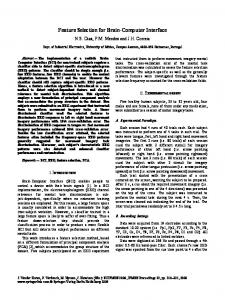
A variety of 3D colour spaces are used to allow precise colour specification in different technological fields. Ideally, each point in such a colour space represents a distinct colour, and no colours exist that do not correspond to a point in the space (Judd and Wyszecki, 1975). If the space is also perceptually uniform (MacAdam, 1942), then distances in the space correspond to perceptual differences between pairs of colours. The L*u*v* space shown in Fig. 2 is perceptually uniform.
Fig 2. The L*u*v* We can use this property of the colour space to simplify colour choice for interfaces. First, we colour space construct a rigid colour molecule in the colour space with "interatomic distances" corresponding to the colour distinctions to be maintained between the interface components. Secondly, we position and orient the molecule so that the colours are pleasing. We may repeat the second step at any time, without damaging the distinctions.
2.1.
Colour selection is important
Colour is ubiquitous. We recognise its strong subliminal effects in many areas. For example: • Advertisers use various colour combinations to achieve their ends. Bright, highly saturated primary colours convey a sense of urgency and fun, and carefully balanced combinations of tertiary colours convey a sense of sophistication. • Political parties - indeed whole political ideologies - are summarised by reference to a single colour (“The Greens,” and that clarion call from the 1950s: “Better dead than red”) • Colour-coding is used by many graphic artist to make components of a diagram more immediately recognisable than if they were identified purely by shape or by name. • In the workplace, colours are found to have significant effects on productivity. Greens are often chosen for their restful effect, but large areas of poorly chosen greens can induce feelings of nausea, and reduce productivity. Strong colours are tiring to look at for long periods. Interfaces with garish colours are undesirable; users should be able to concentrate on the task at hand, without being conscious of the appearance of the interface. That is, the interface should be perceptually visible, but cognitively invisible.
2.2.
Colour Selection has become even more important
During the twentieth century, the problem of colour selection has become more important, as opportunities for colouring our environment have increased manyfold. In earlier times, there just weren’t very many colours available to colourists. Although beautiful, highly saturated dyes and pigments are abundant in nature, most decompose and lose their saturation when exposed to light and atmospheric oxygen or in association with mordants (the chemicals used to fix colouring agents to yarn). Furthermore, many of the remaining strong colours (like ultramarine - finely ground lapis lazuli - and Indian yellow - made from the urine of cows fed on mangoes) were, and still are, rare and expensive. Consequently, only a few bright colours (and dull colours too, for that matter) were used, until nineteenth century organic chemists began to dramatically fill in and extend the palette of available and affordable colours. And at the same time as the scientists were reducing the pigment costs, so people’s incomes were increasing. Now, with more money to spend, and a wider range of colours to choose from, we no longer think about colouring as a fortuitous by-product of protection against the elements, or a luxury for special occasions; in fact, we are prepared to spend money to change the appearance of our entire surroundings. Furthermore, more of our environment is fabricated from manufactured, and therefore colourable, materials than in the past. In earlier times, we were surrounded by stone, wool, wood, and brick with their natural, often inherently harmonious, colours. Now we choose colours for our plastic and painted world, often in isolation. As the range of available colours is both wider and more finely graduated than in years gone by, the chances of choosing disastrous colour combinations have radically increased, and questions of colour balance are correspondingly more urgent.
2.3.
Colour selection is difficult
Colour space is large. Even the acknowledged masters of the area have trouble exploring it. Josiah Wedgewood, for example, performed over 10,000 experiments in his efforts to find the colour - called, simply, pale blue - which would best contrast with the white of the applied decoration on his jasper ware (Birren, 1980). Most people aren’t familiar with three dimensional colour spaces. They can’t locate points or measure distances in such a space. We recognise that simplifications (such as “a colour goes with darker or lighter versions of itself”) exist, but we lack tools to map the simplification onto the colour space. Designing a colour scheme in such a state of ignorance is like trying to produce plans for a building without knowing anything about geometry or mensuration. Geometers use set squares, rulers, protractors, and so on for specifying and
measuring important relations in Euclidean space, which they can then map onto physical space. However, the physical universe is a much closer analogue of Euclidean space than of the complex perceptual phenomenon we call colour space and, although analogous tools can be constructed for manipulating relationships in colour space, they are difficult to use. This is not because colour spaces have a complex geometry - they allow us to represent colour relationships in conventional cartesian or polar coordinates - but because they are irreducably three-dimensional. That is, every point in the 3D space is associated with a unique colour, so that it is difficult to produce a meaningful projection of the 3D space onto conventional 2D media.
2.4.
Colour interactions are important
Colours never occur in isolation. Our perception of a colour is invariably influenced by simultaneous contrast (Chevreul, 1839). This differs from the more familiar phenomenon of successive contrast, which occurs when we transfer our gaze from an area of one colour to an area of a second colour. The retinal cells fatigued by exposure to the colours of the first area are temprarily less sensitive to those colours in the second area. Therefore a colour-inverted after-image of the first area is superimposed over the second area, and influences our perception of its colour until the after-image fades. Simultaneous contrast is not caused by retinal fatigue. but by the way the preceptual system is set up to exaggerate differences between adjacent parts of an image. An orange object adjacent to red will appear more yellow, and adjacent to yellow, will appear more red, than if it is viewed against a neutral background. A brown surrounded by bright yellow will appear duller than if surrounded by grey. Chevreul’s experiments with tapestry yarns in the Gobelin tapestry works showed that apparent colour differences in the patterns of carpets with identically-colouired patterns but differently-coloured backgrounds were caused, not by poor quality control in the dyeing of the yarn, but by simultaneous contrast between the pattern colours and the different background colours of the carpets. The simultaneous contrast phenomenon provides objective verification of the idea that colours interact with each other. There are other interactions which are less objectively verifiable, but even more important in choosing colours. Many have been codified into colour selection heuristics. For example, adjacent or diametrically opposed hues (yellow and orange, or red and green) on the colour wheel harmonise, but hues that are a medium distance from each other (such as green and orange) do not. Interior decorators, fabric designers and architects must take these colour interactions into account if their designs are to be successful. In all of these areas of work, colours are viewed only in the context of other colours, and achieving a sense of pleasant overall interaction is at least as important as the attractiveness of the individual colours. Cartography is a particularly interesting field that encounters colour interaction problems, because of the similiarity between the information-carrying tasks of maps and computer interfaces; information is not encoded in interior decoration, fabric design or architecture in quite the same way as it is in maps and computer interfaces. In maps showing elevations, for example, each elevation range is given a colour that is interpolated between a saturated colour for the highest regions where there is not much else on the map, and a light unsaturated colour for low-lying regions that contain roads, rivers, towns, and so on. Colours for the symbols used to represent these features are can be darker and more saturated, because they are smaller, and need to be clearly defined on the map. As maps are primarily a way of correlating a variety of types of information specifically the absolute location, relative location and the nature of a multitude of features - the primary concern is to represent information clearly. However, a pleasant appearance is hardly less important, as many people use maps extensively in their work, and pleasant colour combinations greatly reduce fatigue from long-term detailed study. Computer interfaces share some characteristics with maps. For example, interface features differ in size and importance; they often have to be colour-coded for differentiation; sometimes they can overlap, and need to have clearly distinguishable colours; sometimes they can be guaranteed never to overlap, so their colours can be similar without confusion. In addition, of course, poorly designed colour schemes will lead to user fatigue when interfaces are used for long periods. Systems developers are rarely skilled in considering all these factors when choosing a set of colours for the application as a whole. They are more likely to choose colours for individual components on the basis of their individual attractiveness.
2.5.
Computer programmers are not colour designers
Not only are most system designers total amateurs in designing for colour, but the way colour technology was introduced into the computing arena has virtually ensured that they will follow poor colour practices. Colour displays capable of displaying millions of colours have been widely available since the 1950s. There was nothing inherent in their design or in the design of computers to prevent computers from driving them to their full capacity, but restricted memory on early EGA and VGA video cards meant that only 16 of the most garish from the millions available were used in early colour-capable PC applications. Although this 16-colour restriction is now long gone, many influential PC applications were developed during this time, and today’s application developers, even if they weren’t active during the
EGA/VGA era, grew up using applications that were developed during that time, and have essentially been trained to expect computer applications to use the brightest, most highly saturated colours possible. Worse, just about the time when 24-bit colour became widely available, and computer applications generally started to emerge from the clumsiness imposed by the earlier, restricted colour sets, the World Wide Web has standardised on a 216-colour palette, so that web designers’ colour choice will once again be artificially restricted. To summarise, the ideas used in the Colour Harmoniser have been developed: because • colour selection is important for computer applications • colour selection is difficult • colour selection concerns colour interaction more than individual colours • computer application developers are not trained in colour choice or interaction • computer applications developers have been inured to garish colours
3. EARLIER WORK Early in the twentieth century, Albert H. Munsell, an American painter and academic, developed a colour classification system based on an empirical arrangement of colours into a three dimensional space. He was by no means the first to recognise that colour has three dimensions. Goethe, to pick but one famous example, had anticipated him, but it was Munsell's numeric colour-"naming" system that was adopted by many colour classification bodies, including the CIE, leading eventually to perceptually uniform colour spaces such as the CIE's L*u*v* space (Wyszecki and Stiles, 1967). Munsell also developed techniques, based on the perceptual uniformity of his colour solid, for colour harmonisation, but the commercial success of his earlier work on colour classification has largely eclipsed these more sophisticated but less profitable developments. From the point of view of fine art, Munsell's (1905) colour harmony work, whcih frequently results in desaturated colour schemes, could hardly have occurred at a less propitious time, as abstraction (including colour abstraction) was replacing naturalism apparently inexorably. However, Munsell's desaturated harmonious colour schemes were adopted by people with more conservative needs; book designers in particular, who need to achieve subtle effects with colour balance and harmony, adopted his methods for combining colours in graphic design. Today’s system designers are just such another group. They have, by and large, no desire to attain a deep understanding of colour, but they have to produce applications that are pleasant to look at and easy to work with. There can be quite complex constraints on the colours used for interface components if text is to be readable, and other diagrammatic components are to be distinguishable from each other and the background, and neither nondescript nor garish. System designers need a systematic way of determining sets of harmonious colours that will conform to such pragmatic constraints. We will show how the techniques proposed by Munsell can be developed into a software tool for assisting developers to express their personal colour preferences, to fulfill the pragmatic requirements of the application, and at the same time automatically produces a colour combination that conforms to common rules regarding colour harmony. Munsell’s techniques are based on the idea of a three-dimensional colour space. Under normal interior lighting conditions, this space is bounded, so it is convenient to refer to it as a colour solid. The first of the three independent colour dimensions of this solid is called hue. Newton's (1672) prism split sunlight into five1 constituent hues, red, orange, yellow, green, blue, and intermediate hues. Our perceptual system synthesises a nonspectral sensation, purple, from the two colours at the ends of the spectrum, red and blue, and thus we perceive hues as a cycle. So hue is a measure of a colour's position on a circle traversing red orange, yellow, green, blue and purple and back to red again as well as many the nameless intermediate hues. Although this “11/2D” circle is popularly called the Colour Circle, and regarded as a complete description of the colour universe, it does not by any means encompass the full range of perceivable colours. In order to find the rest of the colours, we must incorporate two other dimensions.
1
Newton had mystical pretensions; he believed that there should be seven hues, so he invented a hue between green and blue, which is not recognised by most people. and which he called indigo. He called in an assistant from another room who invented the hue violet, which is not the colour we recognise as purple.
The second dimension of perceptual colour is value, or lightness. In a printed or painted image, the perceived lightness of a coloured area is directly (but not linearly) related to the amount of incident light reflected by the image. In a video image, the lightness at a point on the screen is directly related to the total amount of light emitted from that point. The two-dimensional hue/value model is still insufficient. For example, it does not describe the difference between dull colours like brown and beige and their bright versions, orange and yellow. This requires a third dimension called chroma or saturation. Turning up the colour on a TV set to change the image from monochrome to a full colour increases the saturation of its colours without altering their hues or values. Greys are zero saturation colours, with undefined (or any) hues. Again, it is convenient to visualise this in terms of video technology. A pixel is coloured grey when all three dots are turned on equally. When their intensity is zero or maximum, the "grey" is black or white respectively. In general, fully saturated colours involve some combination of one (giving red, green, blue) or two (giving orange, yellow, purple) phosphors, and unsaturated colours involve some combination of three phosphors. Munsell attributes the idea of a symmetrical (shperical) colour solid with the most saturated colours on its equator to Runge (1810). However, he discovered empirically that, if the positions of the colours are to accord with our perceptions, the highest saturation yellows and blues are respectively higher and lower than the equator, and respectively outside and inside the surface of the “ideal” sphere. To allow perceived differences between colours to be measured directly, he devised a complete, perceptually uniform, colour space. Distances in any 3D colour space will provide some measure of colour difference, but only in a perceptually uniform space will distances be proportional to human perceptual differences between colours. Munsell's original space has been improved upon by MacAdam (1942) and Farnsworth, (1957) and the CIE’s L*u*v* and L*a*b* colour spaces (Judd and Wyszecki, 1975). Munsell used his colour classification solid as the basis of his colour harmony system. Like other authors, principally Itten (1973), he theorised that an image would look harmonious if it produced an overall impression of being "centred" on grey, preferably middle-value grey. In order to ensure this, he calculated the colour strength of a colour region as the product of its area, its lightness and its saturation. Although, strictly speaking, saturation is not bounded, it is convenient to regard both lightness and saturation as running from 1 to 10. A colour scheme based on complementary colours a and b would be balanced if cs a .∑ areaa = csb .∑ areab , where csa (colour strength) is saturationa x lightnessa . A small area of high colour strength a would therefore balance a large area of low colour strength b.
3.1.
Applying Munsell’s approach in practice
It seems unlikely that Munsell intended painters to use his formula precisely - though Seurat might have been tempted to do so - but such a precise formulaic approach provides an ideal basis for a tool for allocating colours to components of computer interfaces, which are not fine art, but need to look harmonious. Before it can be applied, however, there are certain practical problems to be solved. First, interfaces can generally be expected to contain more than two differently-coloured regions, so the balancing has to take into account a variety of colour strengths. Secondly, the perceptual uniformity of Munsell's space is compromised in certain regions, so a more accurately uniform space is required. Thirdly, a system for assisting users to design a computer interface will itself have to have an interface, which will have to facilitate the location of colours which are unique everywhere within a 3D space, using a display technology which is only capable of showing surfaces. Fourth, capturing interface characteristics is a prerequisite to using interface characteristics as a basis for the choice of colours for the interface. It is important to capture as much information as possible to produce a beautiful interface, but for the system to be usable, it is important to minimise the effort involved in defining the interface characteristics. Consider applying Munsell’s approach to the development of a simple two-colour (red-green) complementary colour scheme. The designer would first measure the areas which were to be coloured. There might be a single, solid region of each colour, or an arbitrary number of smaller regions included in the total area; this is of no concern, as it is the total area that counts. (Indeed, in the computing environment, it would be simple to subdivide and intermix the areas repeatedly to produce a uniform "dithered grey" screen made up of appropriate numbers of red and green pixels. Athough this might be a little stark as a user interface, it would be consistent with Munsell's approach.) After measuring the areas, the designer would choose a colour for one of them. This would have to be located on a Munsell colour chart to determine its precise hue, chroma and value, to allow the total colour strength of the regions with that colour to be calculated. In the Munsell colour space, hue is angular (although his units are decimal) so the second colour would have a hue 1800 away from that of the first colour. The value and chroma of the second colour would be next be chosen, so that the product of its colour strength and area equalled the colour strength of the product of the colour strength and area of the first colour. That is, areaC1 x value C1 x
chromaC1 = areaC2 x value C2 x chromaC2 . The designer would thus have a certain amount of freedom in choosing the value and chroma of the second colour, increasing one while decreasing the other. Finally, the Munsell colour samples with the chosen values hue, value and chroma would be matched in printer’s ink or paint, and the artwork produced. This is clearly not a process which is likely to appeal to many designers. There’s too much drudgery involved, both mathematical and mechanical. However, by giving the user access to Munsell’s technique via an intuitive interface and hiding the calculation, a computer could significantly reduce the drudgery in formulating a harmonious colour scheme. Interestingly, although many computer applications provide WYSIWYG colour selection interfaces, they don't simplify colour selection much, as they overemphasise the selection of single, highly saturated colours, and the way they project the three-dimensional space onto two dimensions makes the location of a particular, preconceived colour difficult.
4.THE COLOUR HARMONISER Let us first consider how a purpose-built computer application could simplify the task of choosing a two-colour colour scheme. The designer still has to specify the total area of each colour (possibly by drawing the image), and select one of the colours. A Graphical User Interface can be used to simplify the latter task. The application can then calculate the area x colour strength product for the first colour, and consequently for the second colour. It then presents the user with a line of colours, all of which have the necessary hue to counterbalance the first colour, and a (value x chroma) product, selected to satisfy the requirement that areaC1 x value C1 x chromaC1 = areaC2 x value C2 x chromaC2. The user chooses a particular colour from the line and the computer updates the interface with the chosen colours immediately. None of this has required any calculation by the user, and the colour-matching stages are eliminated. All colour schemes are inherently intended to restrict the colourist's choice, but users may nevertheless feel that their freedom to exercise personal choice has been a little compromised (though the choice of the first colour was unrestricted, and there is at least an element of personal preference in the determination of the second colour). If this were felt to be insufficient, the software could simply suggest an “ideal” colour scheme and provide a direct manipulation interface for the user to alter it according to special requirements, or her or his own taste. The project described herein is a step towards the achievement of such a system. It will involve developing the Colour Harmoniser, a piece of software to address a particular type of design problem, the design of colour schemes for computer interfaces. There are several reasons for choosing this as the first application area. It is an area where the professionals (applications programmers) are unskilled. Therefore, whereas artists might feel that such a mechanised approach was a slight on their artistic integrity, applications designers seem likely to welcome it as a way of improving the results they can obtain without having to learn a whole lot of colour theory. The development of computer interfaces is also clearly an area in which the processing power of computers will be available to the user, so it is appropriate to take advantage of this. Finally, the effect of a colour scheme in a computer interface which may be used 8 or more hours a day needs to be harmonious if the interface is not to be visually exhausting 2. The Colour Harmoniser will, in some respects, be more ambitious than might be inferred from the two-colour example described above. First, it will allow for colour schemes with more than two colours. Most interfaces have a large number of icon types - possibly dozens - and they are all likely to need to be coloured differently, so it is necessary to be able to generate a colour scheme that maintains overall harmony between many coloured items. Secondly, in a computer interface, it will be necessary to ensure that most components are clearly distinguishable from the background; that some are distinguishable from each other; and that some are coloured identically. There may also be some that pairs of components that have no distinguishability interaction (for example, if A is completely enclosed by B, then its colour need have no interaction beyond general colour harmony with that of C). Thirdly, the planned software takes account of more parameters than just size in determining the colour strength of a colour region in the image. In a computer interface, some components are more important than others; they therefore “deserve” to be coloured more strongly than less important components. Similarly, components that are only on the screen for a short time can be coloured more strongly than components which stay on the screen for a long time. Examples of the two extremes are 2
There might also be a call for inharmonious colour schemes; warning messages in nuclear power stations, for example, might be better if they didn’t have a soothing appearance, and spooky computer games set in dungeons could benefit from a disturbing colour scheme. Such schemes can probably be produced using rules complementary to those identified by Munsell.
the background for a window (big, long-lived, and unimportant) and warning messages (small, temporary, and highly important), which should be dull-coloured and vivid respectively. The project also falls short of the above description in one, hopefully unimportant, respect. It does not take into account the exact area of interface components. Most applications are not static. Graphical editors, for example, allow the user to deploy various interface components on the screen, and computer games change the appearance of the screen more or less unilaterally, though in response to user input. Thus the application designer cannot predict the precise amount of screen real estate which will be occupied by each colour. If Munsell's formula were applied strictly, the colours of screen objects would have to change when their area changes. This is certainly technically feasible, but it would probably also be psychologically disturbing, and the present authors feel that a static (though changeable by the user) colour scheme would be preferable. Thus the application developer will have to estimate the area that the various screen components will occupy.
5. Extending the concept The discussion so far has concentrated on mathematically tractable aspects of colour selection. The geometrical model described above has been related only to complementary colour schemes. The model can be extended so that it incorporates a variety of other common colour-scheme heuristics. Single-colour-and-black, single-colour-and-white, single-colour-and-grey, analogous, split complementary, and full-spectrum colour schemes can all be mapped onto geometrical shapes in the threedimensional colour space, and a single general algorithm for generating a specific colour scheme, taking colour region area, importance, and longevity into account can be formulated (see later discussion). However, there are many informal colour selection heuristics which do not seem to fit into the geometrical model, and extra work will be necesary to analyse such heuristics. The first part of the analysis will consider whether it is possible to augment the model to allow them to be taken into account. If important heuiristics turn out not to map neatly onto the geometrical model, it will be necessary to develop a knowledge-based system to incorporate this less formal knowledge. Shneiderman (1992) warns us: “No simple set of rules governs use of color, but a number of guidelines can become the starting point for designers.” He then goes on to list a number of such rules, all fairly vague, and possibly contradictory. Examples are: Use color conservatively Be consistent in color coding Limit the number of colors Be alert to common expectations about color codes Recognize the power of color as a coding technique Ensure that color coding supports the task Have color coding appear with minimal user effort
Be alert to problems with color pairings Use color changes to indicate status changes Use color in graphic displays for greater information density
Place color coding under user control
Beware of loss of resolution with color displays
Design for monochrome first
Color fidelity may degrade on other hardware
Use color to help in formatting
Printing or conversion to other media may be a problem
It need not be impossible to incorporate such informal guidelines into the mathematical model One might encode the first rule by advising a user to reorient the colour molecule closer to the grey axis of the colour space if the sum of colour strengths for the interface components exceeded some empirically determined limiting value. The second major component of the research project, after the first prototype of the Colour Harmoniser has been constructed, will involve developing a database of such informal guidelines, and the development of an KBS (Knowledge-Based System) for applying them. The database will be constructed from an intelligent reading of a variety of design-related literature, such as Web design guides, books on graphic design, advertising layout, and so on, and discussions with design professionals. The guidelines will be arranged into a taxonomy. At this stage, it is expected that they will fall into three main groups; guidelines which seem informal, but can be incorporated into the mathematical model (such as the "Use color conservatively" example above), guidelines which can easily be encoded into an intelligent help system, and guidelines which seem to defy automation. The KBS aspect of the project will involve encoding the first two categories, and attempting to minimise the number of guidelines that fall into the third category. At the same time as this KBS aspect of the system is being explored, there will be an opportunity to extend the original system to deal with more difficult types of colouring. The discussion hitherto has dealt with interfaces involving solid areas of colour. Textured areas and colour gradients are becoming an important component of many interfaces; extending the
b'ground c'ponent lrgend wire terminal
size 1000 1 3 100 1
importance longevity 1 10 10 6 10 8 8 8 10 8
b'ground distinct null distinct distinct
c'ponent distinct distinct distinct distinct
legend null distinct null null
wire distinct distinct null
terminal distinct distinct null identical
identical
Fig 4: A table showing the important characteristics of the circuit diagram image mathematical model to cope with these seems quite feasible, and appropriate after the first phase of the project has been completed. In both cases it would seem appropriate to develop a weighted average of the colour strengths used in the textured or gradated area, by summing the contributions from each component colour and considering the average of the whole as the contribution of the textured or gradated area. In fact, this approach has been foreshadowed by the earlier discussion relating to subdividng a notional single area of colour into smaller and smaller subunits, until single-pixel regions with the effect of a dithered grey are achieved. develop er
6.A brief description
characteristics cap ture
colour scheme asse mbly
ap p lication redesign
colour scheme instantiation
l na mi ter
ba c
wi
re
The developer and the end user see the Colour Harmoniser differently
kg r co oun d mp on e n leg t en d
Figure 3 shows a model of the Colour Harmonsier’s two part architecture. Only the application developer will see the first part. It will capture data about the application under development. It will assemble a prototype of the colour scheme, called a colour molecule. The second part of the system will be accessible by both the application developer and the day-to-day user. It will allow a colour molecule to be positioned arbitrarily within the colour space so that a specific colour scheme, based on the characteristics entered by the developer, can be instantiated. The interface characteristics generated by the application developer are clearly an important aspect of the system. They will include a list of the types of icon which will be used in the application, and the characteristics of each icon type: the total area it occupies, its importance, and its longevity. The application developer will also specify the user interaction between each pair of icon types used in the interface. Some pairs will have to be distinguishable. The interface background, for example, will generally have to have a distinctly different colour from everything else on the screen, so every icon pair that includes the background will have the interaction "distinct". Some pairs will have a null interaction (because they never overlap or abut, so it is not Fig. 3. important that their colours are distinct). Some pairs will have to be given identical colours. For example, the application developer might decide that wires and connection terminals in an electronic circuit drawing package should be coloured identically . Let us follow the electronic circuit editor example through in some detail. Figure 5 shows the icon types used in the interface: background, component (AND gate, OR gate, etc), legend (label on a component), wire, terminal (an attachement point for wires). The background is large, unimportant and long-lived. The other icons are all more important and shorter-lived. The background has to remain distinct from all the icon types except the legends, which are confined within the components. Components must remain distinct from all the other component types. Wires and terminals should be identically coloured, and distinct from components and the background. These characteristics are summarised in the table shown in Figure 4 - which could be a prototype design for the interface used by the first part of the Colour Harmoniser for capturing interface characteristics (although it would have space problems if the number of components grew much larger).
IN AND
NOT
OUT
OR
OUT
IN
IN
Fig. 5: Components to be coloured in a simple electronic circuit diagram
6.1.
The colour molecule and the abstract colour scheme
The second part of the Colour Harmoniser makes use of these characteristics of individual interface components and component pairs to produce an optimal set of colour relationships that should be maintained to ensure a usable interface. Mapping this abstract colour scheme onto the colour solid generates a set of points that in turn correspond to a set of interface component colours. However, the mapping takes place in two phases. In the first phase, only the relative positions of the colours within the space are defined. This results in a model of the colour scheme which is rigid, but capable of being repositioned. In this respect, it is much like rigid ball-and-stick models of simple molecules that chemistry students build and examine from all sides to gain an appreciation of the three-dimensional structure of a chemical species. This mobile model of the colour scheme is therefore called a colour molecule. Its important feature of the colour molecule is that its rigidity maintains the colour relationships between interface components, but its mobility allows the colours themselves to remain unspecified3. Thus the application designer has artistic freedom - within limits - to choose a colour scheme for the interface. The limits are necessary to maintain the necessary colour relationships that ensure the interface is usable. The second phase of the mapping fixes the molecule in the space, and thereby associates all of its atoms with specific colours. Since the colour space is three-dimensional, this can be achieved by assigning absolute colour space coordinates to three atoms (or two, for linear molecules). In the second part of the Colour Harmoniser, the user can experiment with different colour schemes by repositioning and reorienting the colour molecule within the colour space. The rigidity of the colour molecule and the perceptual uniformity of the L*u*v* colour space ensure that the necessary colour differences between the colours will be maintained in any MPO (Molecular Position and Orientation). If the space were perceptually non-uniform, two atoms that were clearly distinguishable in MPO1 could become indistinguishable in MPO2, even though their separation within the space remained constant.
6.2.
Constructing the colour molecule
The shape of the colour molecule is obtained by a process analogous to the chemical structure determination technique called molecular packing analysis (Kitaigorodskii, 1970, Williams, 1966, 1967). In this technique, a model of an n-atom subject n m
molecule is rotated in the regular structure of its crystal, until
∑∑
i = 1j =1
interaction i,j
, the total interaction energy between its
atoms and the m surrounding atoms, has been minimised. This is the orientation which the molecule will have in crystals of the solid. The thin lines in the Figure 6 depict the interactions between one atom in the subject molecule (shown using thick lines) and some of its neighbours within some arbitrary cutoff distance (the diagram becomes cluttered if all the interactions are depicted). We shall modify Kitaigorodskii’s technique slightly to predict the configuration of a colour scheme molecule. When dealing with the configuration of chemical molecules, we fix the relative positions of a number of molecules and spin them around till we find the optimum configuration. When dealing with colour molecules, we fix the overall shape of a single molecule so that it corresponds to one of the common colour-selection heuristics (see below), and allow the individual colour atoms to slide along this shape - as though they were beads on a wire frame - to find the optimum configuration.
7.The abstract colour scheme When the colour atoms are eventually positioned within the space, their positions will define actual colours, but at the minimisation stage, the position and orientation of the molecule within the colour space are unspecified. Thus a colour molecule might have the shape of an equilateral triangle, but would not at this stage be associated with the three primary colours (or the three secondary colours, or three of the six tertiary colours, for that matter). It would simply specify that the three colours which are eventually chosen by positioning the triangle in the colour space will be a Fig. 6 The interaction energy between certain perceptual distance apart, corresponding to the length of the side of the atoms of the subject molecule the triangle. and the surrounding atoms is
calculated (only some of the interactions are shown) 3
cf. building plans that specify locations in self-relative coordinates; they do not specify absolute geographical locations. The orientation of buildings with respect to the vertical is usually regarded as fixed, however, whereas the colour molecule is free to rotate in any direction.
Each of the standard rules for deriving a colour schemes corresponds to a simple shape in three-dimensional colour space. The standard rules, and the shapes of the corresponding colour molecules are: Harmonious colour schemes can be produced by varying the saturation of a single hue OR varying the value of a single hue combining various saturations of a single hue and grey combining various saturations and values of single hue and black combining various saturations and values of a single hue and white combining a various saturations and values of a hue and its complement combining various saturations and values of a hue and two colours on either side of its complement combining a set of colours of similar hue combining colours that extend over the full range of hues
Heuristic
The corresponding colour molecule will be
(single hue)
a straight line or simple curve between two points in the colour solid with the same hue a single-hued straight line or simple curve between a point in the colour solid and the grey axis a straight line between a point in the colour solid and black a straight line between a point in the colour solid and white a straight line between two points in the colour solid, passing through the grey axis a Y-shape from a point A in the colour solid, to two points B and C spaced equal distances away from a point A’ directly opposite the first point a short horizontal line or arc passing through not more than approximately 25% of the hues an ellipse
(single hue and grey) (single hue and black) (single hue and white) (complementary) (split complementary) (analogous) (full-spectrum)
All of these colour schemes are well-known, although Munsell seems to be unique in recognising the full-spectrum scheme as a generalisation of triangular, square or rectangular, pentagonal, etc colour schemes described by others, such as Johannes Itten. Munsell also informs us that “any path in the Colour Sphere, and some paths outside it, which are themselves orderly in form and interval will lead through a series of colours which accord, and when used together will render the agreeable sensations which we seek in all colour relations,” although he describes no other such path.
8.Using Colour Molecules to Develop a Colour Scheme In order to determine the position of the colour atoms in the colour molecule, the user will first specify a type of colour scheme (complementary, split complementary, etc.). The Colour Harmoniser will then generate a wireframe shape corresponding to this colour scheme, and position atoms for low colour-strength components near the centre of the wireframe, and atoms for high colour-strength components closer to its extremities. At this stage, the atoms are free to slide along the wireframe. The atoms corresponding to any pair of components that should remain visually distinguishable from each other will experience a repulsive force, R, represented by the following expression: R ∝ importancea x importanceb x longevitya x longevityb / (sizea x size b). Thus two small important components that need to be visually distinguished from each other will have strongly repelling colour atoms, to give the components very different colours. If the application developer has specified zero interaction between two interface components, then the repulsive force between their atoms will be zero (though it maybe sensible to make this a small positive value, so that only items that are to be coloured identically will be given exactly the same colour). Finally, interface components which are to be coloured identically will be tied together, but free to move as a pair on the wireframe. The Colour Harmoniser will then adjust the positions of the atoms along the wireframe to minimise the total interatomic repulsive force. The configuration that results will be the (rigid) molecular structure of the interface’s abstract colour scheme and the user can reposition it within the colour space to produce a wide range of specific colour schemes.
b'ground c'ponent legend wire terminal
size (pixels) 1000 100 1 1 5
importance longevity b'ground (0-10) (0-10) 1 10 8 6 distinct 10 8 null 8 4 distinct 10 8 distinct
c'ponent
legend
wire
terminal
distinct
null distinct
distinct distinct null
distinct distinct null identical
distinct distinct distinct
null null
identical
Consider the electronic CAD package referred to previously. The designer has entered a table of data for interface components. The Colour Harmoniser uses the information in this table to determine how “striking” each component should look. A “strikingCoefficient” for each interface component is calculated according to some formula like strikingCoefficient = 2*importance - 3*log(size) - longevity Thus the strikingCoefficient associated with each of the interface items is: legend wire terminal component background
20 - 0 - 8 16 - 0 - 4 20 - 0.7 - 10 16 - 6 - 6 2 - 9 - 10
= = = = =
12 12 9.3 4 -17
Unstriking items should be dull-coloured; striking items should be strongly coloured. Thus unstriking interface items are placed towards the centre of the colour molecule wireframe, and striking interface items are placed towards the extremes of the wireframe. Consider, for example, a complementary colour scheme, for which the molecule is a straight line passing through the grey axis, and ignore, for the moment, the entries in the second part of the table, which specify that some items are to be coloured identically. The Colour Harmoniser starts with the least striking item, and places its atom at the midpoint of the line. It then moves gradually towards the ends of the line, places atoms for successively more striking items alternately on one side of the midpoint and the other. Thus the order of the above items would be: (legend, terminal, background, component, wire). Let us now take into account the fact that the designer has specified that the colour of the wire and terminal are to be identical. In order to ensure that this occurs, the Colour Harmoniser coalesces these two items into one, which we shall call term/wire for convenience, and allocates it the strikingCoefficient value of the more striking of the two. That is, the list of items and strikingCoefficients is reduced to legend 12 term/wire 12 component 4 background -17 so that the atoms are allocated to the colour line in the order: (term/wire, background, component, legend). Aftert establishing this initial order, the Colour Harmoniser minimises the interacton forces between the atoms in the molecule.
9.The pre-prototype Pilot Colour Harmoniser Parts of the system have been implemented, to test the validity of the concept and the algorithms, and to gain insight into the design of an interface that will hide the model’s computational complexity and highlight its perceptual accuracy. The first test involved applying the optimistion algorithm to the interface components of the electronic drawing package. It operated as expected; that is, the algorithm correctly indicated that • small items - wires and terminals - should be given a strong colour that contrasts strongly with the background. • medium-sized items - components - should be given a medium-strength colour that constrasts sufficiently with the background for the components to be clearly visible • the single large item - the background - should be given a dull middle colour. The test was performed using a hard-coded set of interface parameters (icon size, importance, distinguishability from other icons and so on). The output from the test was a set of positions oalong a linear colour molecule; these values were not used to drive a live update of a circuit diagram, as they would be would in a production system. The results of the second test were more equivocal. This test involved constructing a trial interface with which the user could manipulate the colour molecule directly in the l*u*v* space. Showing a three-dimensional space in which the value at every point is unique is itself non-trivial. It was hoped that a step-section through the space, based on a diagram in Birren (1980), (see figure 7) would give the user a good feel for the molecule’s location in space. However, this diagram is based on a colour solid with a circular cross-section. The trial Colour Harmoniser interface allows the user to explore the complete colour space by rotating the irregularly shaped l*u*v* solid, while the step section remains stationary. However, the outline of the intersection between these two complex three-dimensional shapes is highly asymmetric and, as the solid rotates, its shape varies continuously. The colours at the outline are fully saturated, and they act as a powerful distraction from the more subtle colour variations which are occurring inside the rotating solid - which are the main point of the interface.
Figure 7. Birren’s section through the colour solid, showing variations in hue, saturation, and value on a single diagram, (and some of the shapes that result when it is mapped onto the l*u*v* colour solid.) Nevertheless, rotating the shape and keeping the colour molecule fixed allows the user to choose quickly from a large number of interface colour combinations, for very little physical or mental effort. In the trial interface, the colour combinations are plotted on a vertical line (corresponding to a linear, complementary colour scheme), and the user can halt the rotation at any point and apply the resulting colour combination to a mock-up of the electronic CAD package. The colour schemes that result from this are subtle, often unexpected, and mostly harmonious. It is possible to generate carish colour schemes that nevertheless obey the usual precepts of colour harmony. For example, by orienting the colour molecule horizontally or by orienting it to combine high values of naturally dark colours (like blue and red), with low values of naturally light colours (like yellow). However, when such a combination is selected, it is only a moment’s work, using the interactive direct manipulation interface to alter it to something more pleasing. Because of the ease with which the colour combinatison can be altered, it seems reasonable to give the user (in addition to the application designer) the ability to manipulate orientation of the colour molecule, and thereby customise the colours for the application while using it. Altering the parameters comtrolling the position of the colour atoms in the molecule, would remain the responsibility of the application designer. Naive colourists tend to use hue as the first means of distinguish objects on the basis of colour, and value as the last; experienced colourists reverse this order. The Colour Harmoniser does not explicitly reinforce the latter order of importance except that it colours the picture immediately. It should therefore be immdiately apparent that orienting the colour molecule horizontally produces poor colouration; correcting this is simply a matter of dragging the molecule to a vertical orientation. The Colour Harmoniser could incorporate other cultural attitudes to colour by adding colour molecule wireframes that corresponded to different cultures’ perceptions of appropriate ways to combine colours. The underlying l*u*v* model in not culture-specific, as it is based on human colour perception, which is thought to be universal.
10. References 1 2 3 4 5 6 7 8 9 10 11 12 13 14 15
Birren, F.; A Grammar of Color; Van Nostrand-Reinhold, 1969; pps 40-78 Birren, F.; Colour; Mitchell Beazley Arts House, 1980; pps 142 - 145, 217 Cerbus, G. and Nichols, R.; PersonalityVariables and Response to Colour; Psychological Bulletin, 60, 6, 1973 Chevreul, The Principles of Harmony and Contrast of Colours and their Applications to the Arts, 1839; quoted by Hilary Page, The Artist; 113, 8, 1998, p23 Farnsworth; A temporal factor in colour discrimination; Visual Problems of Colour, II, Nat. Phys. Lab. Symp. No. 8. HM Stationery Office, 1958 p429, cited in Wyszecki and Stiles, 1967 Itten, J., The Art of Colour; New York: Van Nostrand Reinhold, 1973 Judd and Wyszecki; Color in Business, Science and Industry; Wiley Interscience, 1975 Kitaigorodskii, A.I., Organic Crystal Structures; Adv. in Struct. Res. by Diff. Methods, 3, 1970, p173 MacAdam, D.L., J. Opt. Soc. Am., 32, 1942, p247 Newton, I.; The New Theory about Light and Colours; Philosophical Transactions of the Royal Society, 80, Feb19, 1672, 3075-3087, Quoted in Thayer, H.S., (Ed.) Newton’s Philosophy of Nature, Hafner, 1953 Travis, D.; Effective Color Displays: Theory and Practice; Academic Press 1990 Williams, D.E.; J Chem. Phys., 45, 1966, p3770 Williams, D.E.; J Chem. Phys., 47, 1967, p4680 Wright, W.D.; The Measurement of Colour; Hilger 1969 Wyszecki and Stiles, Color Science, Wiley 1967