Energies 2012, 5, 4697-4710; doi:10.3390/en5114697 OPEN ACCESS
energies ISSN 1996-1073 www.mdpi.com/journal/energies Article
Combined Optimal Sizing and Control for a Hybrid Tracked Vehicle Yuan Zou 1,*, Fengchun Sun 1, Xiaosong Hu 1, Lino Guzzella 2 and Huei Peng 3 1
2
3
National Engineering Lab for Electric Vehicles, School of Mechanical Engineering, Beijing Institute of Technology, Beijing 100081, China; E-Mails:
[email protected] (F.S.);
[email protected] (X.H.) Institute of Dynamic Systems and Control, Department of Mechanical and Process Engineering, Swiss Federal Institute of Technology, Zurich 8001, Switzerland; E-Mail:
[email protected] Department of Mechanical Engineering, University of Michigan, Ann Arbor, MI 48109, USA; E-Mail:
[email protected]
* Author to whom correspondence should be addressed; E-Mail:
[email protected]; Tel./Fax: +86-10-6891-5202. Received: 26 July 2012; in revised form: 4 November 2012 / Accepted: 12 November 2012 / Published: 19 November 2012
Abstract: The optimal sizing and control of a hybrid tracked vehicle is presented and solved in this paper. A driving schedule obtained from field tests is used to represent typical tracked vehicle operations. Dynamics of the diesel engine-permanent magnetic AC synchronous generator set, the lithium-ion battery pack, and the power split between them are modeled and validated through experiments. Two coupled optimizations, one for the plant parameters, forming the outer optimization loop and one for the control strategy, forming the inner optimization loop, are used to achieve minimum fuel consumption under the selected driving schedule. The dynamic programming technique is applied to find the optimal controller in the inner loop while the component parameters are optimized iteratively in the outer loop. The results are analyzed, and the relationship between the key parameters is observed to keep the optimal sizing and control simultaneously. Keywords: combined optimization; hybrid tracked vehicle; optimal control; optimal sizing
Energies 2012, 5
4698
1. Introduction Hybrid propulsion systems for tracked vehicles are being actively pursued, owing to their improved fuel economy, significant on-board electricity supply and stealth operation ability. Some hybrid powertrains have been applied to tracked vehicles, and the engineering and prototype implementation was reported [1–4]. Compared to hybrid wheeled vehicles, research on hybrid tracked vehicles in an optimization setting is still scanty. Constrained by the component power density and packaging space, a dual-motor drive structure is adopted for a heavy-duty hybrid tracked vehicle, as shown in Figure 1. The two sprockets are separately powered by two electric motors. A diesel engine-generator set and a traction battery pack provide the two motors with electric energy. The vehicle’s drivability like heading or turning is maintained by controlling the speeds/torques of the two motors, while the diesel engine-generator set is controlled to regulate the power distribution between the generator and the battery. This vehicle mostly operates as a serial hybrid, except during the turning, when the outside motor propels and inside one performs braking. The supervisory controller assesses the driver intention and coordinates the work of engine-generator set, battery pack and the two electric motors in an optimal way. Figure 1 also shows a safety design, where a resistor bank is installed and can be switches in case the DC bus voltage exceeds a threshold value. Figure 1. Dual-motor drive structure of the hybrid tracked vehicle.
Several studies have focused on the sizing and configuration design to maintain the drivability, and the design of the control strategy for optimal fuel economy [5–8]. Relatively little work has investigated the parameter sizing and control strategy simultaneously. A general iterative design methodology was used for the optimal design of the plant and controller [9] and it has been applied successfully to the combined automotive suspension and fuel cell optimization [9,10]. In terms of optimal control design, the dynamic programming techniques have been widely applied to wheeled hybrid vehicles and recognized by the academic community for its generic applicability for discrete or continuous state problems with constraints [11–14]. In this paper, an iterative combined plant-controller optimization methodology is applied to optimize the key parameters of the powertrain and the control strategy simultaneously for a tracked hybrid vehicle. An automatic process iteratively evaluates the fuel consumption as the sizing parameters vary until the combined optimal sizing and control result is obtained.
Energies 2012, 5
4699
2. Modeling of Hybrid Electric Powertrains 2.1. Calculation of the Power Requirement for the Engine-Generator and Battery Pack The tracked vehicle dynamics are mainly based on the work of Bekker’s and Wong’s [15,16]. When only the longitudinal/lateral/yaw motions are considered, the governing equations are: F r M r mr2 R I z r2 2 Ti ( ri r ) 2 i i0 Bi0 i0 (R B / 2) i0B(R B / 2) Fror Mr r mr2 I z r2 R ( ) T o o i Bi 2 (R B / 2) 2 ( / 2) i i B R B 0 0 0 0
(1)
where Ti, To are the torques of the inside and outside motors, Fri, Fro are the rolling resistance forces of the two tracks, Mr is the resisting yaw moment from the ground, B is the tread of the vehicle, and Iz and m are the yaw moment of inertial and the mass of the vehicle, respectively. r is the radius of the sprocket, i0 is the fixed gear ratio between motors and sprockets, η is the efficiency from motor shafts to tracks, R is the turning radius of the vehicle, and ωi, ωo are the rotational speeds of the inside and outside sprockets, respectively. Considering a steady-state turning, the resisting yaw moment from the ground is calculated by Equation (2) [16]: Mr
t mgl 4
(2)
where µt is the coefficient of the lateral resistance, g is 9.81 m/s2, and l is the contact length of the track. Based on empirical results, µt was found to be [17]: t max (0.925 0.15 R B) 1
(3)
where µmax is the maximum value of the coefficient of lateral resistance, which is dependent on terrain type. The rolling resistant forces acting on the two tracks are: Fri Fro 0.5 f r mg
(4)
where fr is the coefficient of motion resistance of the vehicle in the longitudinal direction. When the track slip/skid is omitted the turning radius R can be calculated from Equation (5): R
B o i 2 o i
(5)
The rotational speeds of the outside and inside sprockets, ωo and ωi, can be calculated from:
o,i
30 vo,i i0
r
(6)
where vo,i are the speeds of the two tracks. Like in Equation (5), an implied assumption of Equation (6) is also that the track slippage is ignored. The electric power Preq requested by the two motors varies as the driving mode changes, especially during braking. Two kinds of electric braking are adopted to reduce mechanical friction brake: resistor
Energies 2012, 5
4700
braking and regenerative braking. To recuperate the braking energy as much as possible, regenerative braking is applied prior to resistor braking. However, resistor-braking is used if the DC bus voltage Udc is higher than a threshold value Uthr for safe operation of the electronic devices. The value of Preq is calculated from Equation (7), where Preq is positive when the electric power outputs and negative when the electric power is recuperated in regenerative braking. It must be noted that in this vehicle, the regenerative braking only happens when Udc < Uthr; otherwise the resistor braking is triggered, and the electric power will be consumed by resistor-heating. In that case, Preq remains positive whenever the electric motors drive or brake: sgn(T1 ) sgn(T2 ) Toomot Ti i mot Preq sgn(T1 ) sgn(T1 ) Ti i mot Toomot
Udc U g , U dc U g = U bat ,
Ig = 0
(15)
Ig > 0
where Ig = 0 occurs when Ug is lower than Ubat and thus the generator is not producing any electric power. In this case the battery pack will supply all the power. The values of the vehicle’s key parameters are summarized in Table 1 below. Table 1. Values of the vehicle’s key parameters. Parameters. Unit Value
m [kg]
Iz 2
[kgm ]
i0
r [m]
B
Ke
Kx −2
−2
[m] [V s rad ] [N m A ]
15,200 55,000 13.2 0.313 2.55
1.65
0.00037
ie-g 1.60
C
Je
Jg 2
l 2
[Ah] [kgm ] [kgm ] [m] 50
3.2
2.0
3.57
Equations (1)–(15) describe the dynamics of the hybrid tracked vehicles. Given the typical driving schedule and the component parameters, Teng should be regulated in an optimal way to determine the
Energies 2012, 5
4703
power distribution between the generator set and the battery pack to achieve minimum fuel consumption. Here the electronic accelerator pedal signal Acceng is normalized between [0, 1] to regulate Teng within the admissible range. 3. DP-Based Strategy and Optimization Equations (1)–(15) are discretized to formulate into a DP problem. The time step Ts is set to 0.1 s considering the balance between computation cost and accuracy. The optimal control Acceng(k) (k = 0, 1, …, N − 1) is pursued to minimize the total fuel consumption during the given driving schedule as follows: N 1
J ( x(0)) Ts F (neng (k ), Teng (k )) i 0
(16)
subject to the following constraints: x(k 1) f ( x(k ), Acceng (k ), Preq (k ))
(17)
| SOC( N ) SOC(0) | SOC
(18)
neng _ idle neng ( k ) neng _ max
(19)
neng (k 1) neng ( k ) n
(20)
I bat _ max_ char I bat ( k ) I bat _ max_ disch
(21)
0 I g (k ) I g _ max
(22)
In Equations (16)–(22), F is the fuel consumption rate determined by neng(k) and Teng(k), normally obtained through a fuel consumption table derived through bench tests. x(k) = [SOC(k), neng(k)], and f represents the discrete dynamics from Equations (1)–(15). The increment of neng is also constrained to emulate the dynamics of the engine. Typically, the HEV control strategy requests the energy balance for the battery pack at the end of the driving schedule, and SOC(N) is hence enforced to equal the initial value. The DP technique is applied to solve the above problem based on the principle of optimality, which is expressed as: J ( x( k )) min {J ( x( k 1)) T s F ( neng ( k ), Teng ( k ))} Acceng ( k )
(23)
where J(x(k)) is the optimal cost function at state (x(k) starting from step k. When (x(k) and Acceng(k) are discretized into the finite states and Equation (23) is solved backwards, the optimal control and corresponding cost are stored and then the optimal solution with the specific initial states is retrieved forwardly by applying the optimal controls through the horizon. The control rule can be extracted from the DP results, as a casual control strategy. However, since some important parameters couple closely with the control, and the DP-based control strategy is just optimal given the particular system parameters, the following combined optimization of the system parameters and control strategy in the synergic way is significant.
Energies 2012, 5
4704
4. Combined Optimization Problem Formulation 4.1. Combined Optimization Framework Given the vehicle system parameters, DP can be used to find the optimal control under constraints for a specific driving schedule. When the system parameters vary in the feasible range and DP is applied iteratively, the optimal combination of the parameters and control will be identified. Four kinds of combined optimization methods were observed by Fathy et al. [9]. In this paper the Bi-level combined plant/controller optimization is adopted, consisting of two nested optimization loops. The outer loop optimizes the fuel consumption by only changing the system parameters. The inner loop generates the optimal control strategy for the parameters selected by the outer loop. These two loops form the integrated plant/controller optimization, which generates the global optimal design for the system parameters and control strategy. The Bi-level combined optimization process is shown in Figure 6. Figure 6. Bi-level combined optimization process. Initial system parameters
DP-based control optimization Meet the optimization convergence criteria?
N
Change parameters
Y Get optimal parameter/control design
4.2. The Scaled Model and Optimization Problem Formulation The scaled models are needed to parameterize the system conveniently during the optimization process. In this paper the engine sizing is fixed and the battery capacity and open circuit voltage is scaled by the scale factors xCAP and xOCV, respectively. Here the internal resistance is assumed to be proportional to the open circuit voltage and inversely proportional to the capacity. The battery capacity, open circuit voltage and internal resistance are calculated by Equations (24)–(27): C xCAP Cbas
(24)
V (SOC) xOCV Vbas (SOC)
(25)
Rint_ ch (SOC) xocv xcap Rint_ ch_bas (SOC)
(26)
Rint_ dis (SOC) xocv xcap Rint_dis_bas (SOC)
(27)
where Cbas is the baseline capacity, Vbas(SOC) is the baseline open circuit voltage of the battery pack varying as a function of SOC. Rint_ch_bas(SOC), Rint_dis_bas(SOC) is the baseline internal resistor varying with SOC.
Energies 2012, 5
4705
Because the gear ratio ie-g between the diesel engine and the generator plays an important role in scaling the engine’s speed/torque into the generator’s range, it is also selected as a parameter to be optimized in the outer loop. The degree of hybridization is adopted to measure the relative power size of the primary power source and the secondary power source. In the serial hybrid configuration for this tracked vehicle, the diesel engine-generator is the primary power source and the battery pack is the secondary power source. To avoid optimal but unphysical solutions, the degree of hybridization is constrained to [0, 0.4] and calculated by Equation (28): x
h
= Pbat_max ( Pbat_max + Pgen_max )
(28)
where Pbat_max is the maximum power battery pack outputs, and Pgen_max is the maximum power the generator provides. The value of Pbat_max is calculated based on the practical current range as defined by Equation (29): Pbat_max
V 2 (SOC) 4 R int_dis (SOC) SOC[0,1]
max
(29)
The combined optimal problem is formulated with all the feasible constraints: N 1 Ts F (neng (k ), Teng (k )) xOCV , xCAP , ie-g , xh i 0 min
(30)
subject to: x ( k 1) f ( x ( k ), Acceng ( k ), Preq (k )) 0.2 xOCV 2 xh 0.4 0.2 xCAP 2 1 ie-g 4 V (0.7) C Eele
(31)
| SOC( N ) SOC(0) | SOC neng _ idle neng ( k ) neng _ max neng ( k 1) neng ( k ) n I bat _ max_ char I bat ( k ) I bat _ max_ disch 0 I g ( k ) I g _ max
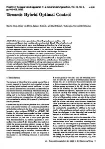
where xocv, xcap, xh, ie-g,neng, Ibat, and Ig are constrained to their respective feasible ranges. The product of the open circuit voltage when SOC = 0.7 and the capacity should be more than the energy value supporting the sufficient stealthy operation range. Notice that ACCeng(k) incorporated in Equation (30) influences Teng(k) directly and is determined in the inner loop by DP method. 5. Results and Discussion The combined optimization is computationally expensive due to the dual-loop iterative process. In order to improve the computational efficiency, once the constraint in the inner loop is violated the current exploitation stops and the cost is set to a large infeasible value. A strong nonlinearity is
Energies 2012, 5
4706
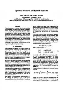
observed and the data shown in the map is a bit noisy. The DOE (Design of Experiments) technique is first applied to explore the response map in all the feasible design spaces based on Latin Hypercube sampling and then the Non-linear Programming by Quadratic Lagrangian (NLPQL) algorithm is applied to obtain the global optimal value [18]. The relationship of the fuel consumption, ie-g and xocv is shown in Figure 7, in which the optimal correspondence between ie-g and xocv is observed explicitly. This means that ie-g increases or decreases with xocv to maintain an optimal fuel economy. Further investigation shows that the voltage range of the battery pack and the engine-generator match well to make the optimal power distribution between them possible. It may thus be concluded that the energy distribution control has a limited influence on the fuel economy without the proper match between ie-g and the voltage range of the battery pack. The proper match is necessary to keep a good fuel economy. It should be noted that the optimal power distribution control plays a valuable role if ie-g and the voltage range of the battery is constrained to the optimal area shown in Figure 7, which allows the component sizing or parameter to be freely selected. Figure 8 shows the engine working points under the optimal control when ie-g and xocv are selected differently. It can be seen that the engine works near the high efficiency area if ie-g and xocv match well, just as the parameter selection D2 in Figure 8, with a lower fuel consumption of 2824 grams. Otherwise the engine works far from the high efficiency area, just like the parameter selections D1 or D3 with 3163 and 3513 grams, 12.0% and 24.4% higher than that of D1, respectively.
0
0
0 288
308
0
298
0
28 80
328
80 31
29 80
318
0 318
31 80
2980 3080
1.4
1.6
1.8
2
i
2.2
D1 32 80
80 28
33 80
288
298
0
308
30 80
D2
0
0
32 80
0.9 0.85
0
34 80 33 80
x
ocv
1 0.95
2880
29 80
3180
338
0
368
0
298
0 358
1.05
3080
0 348
D3
1.1
28 80
Figure 7. The fuel consumption contour (grams) vs. ie-g and xocv.
2.4
2.6
2.8
e-g
Figure 8. Engine operating points in three different parameter selection (xcap = 2, xh < 0.4).
220
20 0
20 0
28 0
T
26 0
1000
22 0
21 0
800 0 30
22 0
210 23 0
0 23
220 230
400
240 250 260 350 280 300
0 24 0 25
200 600
e-g
24 0
/Nm
ocv
1200 25 0
eng
D2(x =0.9, i =2.1, fuel=2824g) ocv e-g D1(x =0.9, i =2.8, fuel=3161g)
230
1400
600
200
210
1600
BSFC map (g/kWh) Max torque D3(x =1.1, i =1.58, fuel=3513g) ocv e-g
21 0
260
280
1800
250
2000
26 350 280 3000
800
1000
1200
n
eng
1400
/rpm
1600
2
350
1800
280 3
2000
Energies 2012, 5
4707
The relationship of the fuel consumption, xcap and xh is shown in Figure 9. The values of xh and xcap must remain in a specific range to obtain the optimal fuel economy. Although this map is a bit noisy, there is an optimal range [0.25, 0.32] for xh. This fact allows us to conclude that in such a kind of hybrid vehicle, xh should be selected with great caution because the fuel economy does not always increase as xh increases. There is a more sophisticated interaction between the fuel consumption, xh and xcap. Figure 9. Fuel consumption vs. xcap and xh.
50 29
1.8
00 30
cap
3100 3150
1 0 310
00 31
30 00
29 50
x
50 28
1.2
0 295
00 29
295 0 290 3000 3050
0
1.4
290
1.6
3000
3000
50 28
0
0 0 305 3020950
0.8 0.15
0.2
0.25 x
0.3
0.35
h
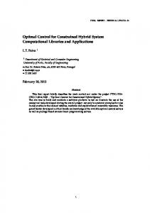
The dynamic evolutions of the system with the parameter selection D1, D2, D3 are shown in Figure 10. D1 and D3 represent two type mismatches of the engine-generator and the battery. The value of ie-g is too higher than the voltage range of the battery in D1, and vice versa in D3. Figure 10. Dynamic history of typical variables in D1, D2, D3. 1 0.5 0 2100
Acc
D1 D2 D3
750 0.72
D1 D2 D3
0.67 560
D1 D3 D3
U
dc
SOC
n
eng
D1 D2 D3
380 500
Ig(D1)
bat
Ibat(D1)
I ,I
Ig(D2)
g
Ibat(D2) Ig(D3)
-200 0
Ibat(D3)
100
200
300
400
500 t /s
600
700
800
900
990
The engine speed is constrained to the undesirable range in D1 and D3. Clearly, DP finds the different controls for the different parameter selections. For D1, the engine always operates in the high speed range to generate electricity, while the engine is idled when the power request is low during
Energies 2012, 5
4708
around 230–260 s. For D1 and D2, the engine works around 900 rpm and 1200 rpm, respectively. The engine frequently generates maximum torque to increase its power output in D1 due to its low speed range. D2 has the relative proper torque and speed output and achieves the lowest fuel consumption. It is clear that the battery tends to be charged or discharged at higher current in D3 than in D2, and it is used less frequently in D1 than in D2. This observation is also useful for the proper battery parameter design. This may lead to the conclusion that the voltage match between the generator at the desired speed range and the battery at admission SOC range is very important. A good match will guarantee the battery can supply the electric power properly, avoiding overuse and insufficient participation. The optimized and initial parameters are shown in Table 2, where ie-g, the battery capacity and the voltage range are solved simultaneously to obtain the results shown in Figure 8 and Figure 9. It should be noted the battery capacity increases by 28.0%, and the voltage decreases to 89.9% of the original level. This helps improve the ability to supply the bigger transient electric current without any significant loss of the battery reliability. A considerable reduction of fuel consumption is achieved, namely 16.2% lower than the fuel consumption under the initial parameters. Table 2. The combined optimal design vs. the initial design. Optimal design results Fuel C* V*(1) consumption* x cap x h i e-g [Ah] [V] [grams] 0.90 1.68 0.25 2.15 64 436 2820 x*ocv
*
*
*
Initial design values Fuel Fuel economy C V(1) ie-g consumption Improvement [Ah] [V] [grams] 50 485 1.60 3365 16.2%
Clearly in this hybrid tracked vehicle the parameter selection plays a significant role in the optimal system design and the proper parameter match is a necessary prerequisite for a good fuel economy, especially for some predominant parameters, such as the battery voltage and the generator speed which are influenced heavily by the gear-ratio between the engine and generator. The mismatch results in the limited improvement in fuel economy even through the control optimization. It should also be noted that the fuel economy obtained in the paper is the theoretically best with respect to the current parameter selection and the optimal control. The casual control algorithm approximating DP behavior should be pursued in the following practical controller design, which is not covered in the paper. 6. Conclusions The combined optimization of the sizing and power distribution control for a hybrid tracked vehicle is investigated in this paper. The hybrid electric powertrains are first modeled and verified through test results. The Dynamic Programming technique is applied to find the optimal control given the driving schedule from the field test and particular system parameters. A comprehensive Bi-level optimization framework suitable for the above problem is presented and applied to optimize the parameter sizing and control iteratively. The optimal results are analyzed to disclose the interaction between sizing and control design, which is helpful for the combined system sizing and control design in a synergic way. It clarifies that both the parameter sizing and control optimal design are important equally for the hybrid propulsion of the tracked vehicle. The sizing defines the optimal possibility of the components’ collaborations, and the optimal control identifies the solution matching the sizing and realizes that
Energies 2012, 5
4709
possibility. The parameter selection without the consideration of the optimal control implementation in the later phase is difficult to maintain the combined optimal design. A significant reduction of the fuel consumption is observed. The combined methodology proposed in the paper is instructive to other hybrid propulsion designs. It also should be noted that the large amount of driving schedules involved help find and improve the combined optimal design. Acknowledgements This work is supported by the Natural Science Foundation of China (Grant No. 50905015) and the Sino-Swiss S&T Cooperation Program (Grant No. EG 37-032010). References 1. 2. 3. 4.
5. 6. 7. 8. 9.
10. 11. 12.
13.
Nederhoed, R.; Walker, G.W. Development and testing of series hybrid drive vehicles for military applications. ECS Trans. 2008, 16, 1–10. Shafer, G. Electric Drive M113 Vehicle Refurbishment Project: Sacrament Electric Transportation Consortium RA93–23 Program; FMC Corporation: Santa Clara, CA, USA, 1997. Zou, Y.; Zhang, C.-N.; Sun, F.-C.; Wu, J.-B. Power control of dual-motor electric drive for tracked vehicles. Front. Mech. Eng. 2010, 5, 67–72. Shanmuganathan, U.; Govarthanan, R.; Muthumailvaganan, A.; Imayakumar, A. Modeling and Dynamic Simulation of IC Engine Driven Permanent Magnet Generator Using Matlab/Simulink for Hybrid Tracked Vehicle. In Proceedings of IEEE Electric and Hybrid Vehicles Conference, Pune, India, 18–20 December 2006. Gu, Z.-L.; Wang, S.-Z.; Li, J.-Q. Energy management strategy of multiple objects control for hybrid electric vehicles. Trans. Beijing Inst. Technol. 2006, 26, 303–307. Lyshevski, S.E. Energy conversion and optimal energy management in diesel–electric drivetrains of hybrid-electric vehicles. Energy Convers. Manag. 2000, 41, 13–24. Anh, T. Modelling and Control of Tracked Vehicles; The University of Sydney: Sydney, Australia, 1999. Zou, Y.; Sun, F.-C.; Zhang, C.-N. Dual-motor driving electric tracked vehicle speed-regulating control strategy. Trans. Beijing Inst. Technol. 2007, 27, 303–307. Fathy, H.K.; Papalambros, P.Y.; Ulsoy, A.G.; Hrovat, D. Nested plant/controller optimization with application to combined passive/active automotive suspensions. In Proceedings of American Control Conference, Denver, CO, USA, 4–6 June 2003. Kim, M.-J.; Peng, H. Power management and design optimization of fuel cell/battery hybrid vehicles. J. Power Sources 2007, 165, 819–832. Lin, C.-C.; Peng, H.; Grizzle, J.; Kang, J.M. Power management strategy for a parallel hybrid electric truck. IEEE Trans. Control Syst. Technol. 2003, 11, 839–849. Sundstrom, O.; Guzzella, L. A Generic Dynamic Programming Matlab Function. In Proceedings of the 18th IEEE International Conference on Control Applications, Saint Petersburg, Russia, 8–10 July 2009; pp. 1625–1630. Sciarretta, A.; Guzzella, L. Control of hybrid electric vehicles. IEEE Control Syst. Mag. 2007, 27, 60–70.
Energies 2012, 5
4710
14. Pisu, P.; Koprubasi, K.; Rizzoni, G. Energy management and drivability control problems for hybrid electric vehicles. In Proceedings of the 44th IEEE Conference on Decision and Control, 2005 and 2005 European Control Conference (CDC-ECC '05), Seville, Spain, 12–15 December 2005. 15. Bekker, M.G. Theory of Land Locomotion; University of Michigan Press: Ann Arbor, MI, USA, 1956. 16. Wong, J.-Y. Theory of Ground Vehicles, 3rd ed.; J. Wiley & Sons Press: New York, NY, USA, 2001. 17. Wang, M.-D.; Zhao, Y.-Q.; Zhu, J.-G. The Driving Principles for Tank; Defense Industry Press: Beijing, China, 1983. 18. iSight Software User Guide (4.5 Release); Dassault Company: Cary, NC, USA, 2010. © 2012 by the authors; licensee MDPI, Basel, Switzerland. This article is an open access article distributed under the terms and conditions of the Creative Commons Attribution license (http://creativecommons.org/licenses/by/3.0/).