Dec 15, 2010 - The first phase is devoted to build the dictionary used during .... the code on this BlueGene/P system corresponds to simulating a full .... Other scalable distributed cracking systems ..... assigned to the broken node and informs the root. ... JAVA, Perl and Python), iii) allows applications to communicate across.
Combining Algorithms and Technologies to Speedup Computing Intensive Applications Mauro Bisson
Submitted to the Department of Computer Science in partial fulfillment of the requirements for the Degree of Doctor of Philosophy in Computer Science at the Sapienza University of Rome
December 15, 2010
Contents Introduction
4
1 GPUs and CUDA overview
10
1.1
The CUDA programming model . . . . . . . . . . . . . . . . . . . . 12
1.2
Memory Hierarchy . . . . . . . . . . . . . . . . . . . . . . . . . . . 16
2 Distributed dictionary attacks
19
2.1
OpenPGP Standard . . . . . . . . . . . . . . . . . . . . . . . . . . 20
2.2
Attack Strategy
2.3
2.4
. . . . . . . . . . . . . . . . . . . . . . . . . . . . 21
2.2.1
Dictionary Compilation Phase . . . . . . . . . . . . . . . . . 22
2.2.2
Passphrase Generation Phase . . . . . . . . . . . . . . . . . 22
2.2.3
Passphrase Verification Phase . . . . . . . . . . . . . . . . . 23
Distributed Architecture . . . . . . . . . . . . . . . . . . . . . . . . 27 2.3.1
General Requirements . . . . . . . . . . . . . . . . . . . . . 27
2.3.2
Overall Organization . . . . . . . . . . . . . . . . . . . . . . 27
2.3.3
System Life-cycle . . . . . . . . . . . . . . . . . . . . . . . . 29
Implementation . . . . . . . . . . . . . . . . . . . . . . . . . . . . . 32 2.4.1
MIDIC . . . . . . . . . . . . . . . . . . . . . . . . . . . . . . 33
2.4.2
The dcrack Application . . . . . . . . . . . . . . . . . . . . . 35
2.5
Experimental results . . . . . . . . . . . . . . . . . . . . . . . . . . 37
2.6
GPU Implementation . . . . . . . . . . . . . . . . . . . . . . . . . . 38 2.6.1
Input . . . . . . . . . . . . . . . . . . . . . . . . . . . . . . . 40 1
2.7
2.6.2
Computing Kernels . . . . . . . . . . . . . . . . . . . . . . . 42
2.6.3
Output . . . . . . . . . . . . . . . . . . . . . . . . . . . . . . 45
2.6.4
Code Optimizations . . . . . . . . . . . . . . . . . . . . . . . 45
2.6.5
Results . . . . . . . . . . . . . . . . . . . . . . . . . . . . . . 57
Discussion and future perspectives . . . . . . . . . . . . . . . . . . . 58
3 Multiscale hemodynamics model
61
4 Parallel Molecular Dynamics with Irregular Domain Decomposition
67
4.1
Molecular dynamics . . . . . . . . . . . . . . . . . . . . . . . . . . . 71
4.2
Parallel Molecular Dynamics . . . . . . . . . . . . . . . . . . . . . . 73
4.3
Cell Tiling . . . . . . . . . . . . . . . . . . . . . . . . . . . . . . . . 82
5 Multiscale Hemodynamics using GPU clusters 5.1
5.2
94
Implementation . . . . . . . . . . . . . . . . . . . . . . . . . . . . . 97 5.1.1
Domain Structures . . . . . . . . . . . . . . . . . . . . . . . 99
5.1.2
Particles Structures . . . . . . . . . . . . . . . . . . . . . . . 102
5.1.3
Frontier Management . . . . . . . . . . . . . . . . . . . . . . 103
5.1.4
Particle-Particle Interactions . . . . . . . . . . . . . . . . . . 104
5.1.5
Particle Migration . . . . . . . . . . . . . . . . . . . . . . . 108
Performance Tests . . . . . . . . . . . . . . . . . . . . . . . . . . . 110
6 Multiscale simulation of full heart-circulation system at near redblood cell resolution 6.1
Code Features
6.2
Results
116
. . . . . . . . . . . . . . . . . . . . . . . . . . . . . 118
. . . . . . . . . . . . . . . . . . . . . . . . . . . . . . . . . 127
6.2.1
Strong Scaling . . . . . . . . . . . . . . . . . . . . . . . . . . 128
6.2.2
Hardware Performance Monitoring . . . . . . . . . . . . . . 130
7 Conclusions and future directions
2
132
A Geometry preparation and mesh generation
3
137
Introduction In the present work we study two different, compute-intensive problems. The first is the execution of dictionary attacks to cryptographic systems. Cryptosystems are used everyday by millions of people around the world to lawfully enforce their privacy rights (e-commerce transactions, exchange of reserved data, etc...). While most of the security of cryptosystems lies in the algorithms they use, the growing computational power of commodity computers poses a serious threat since passwords and passphrases used by most of the users of cryptosystems are far from being ideal in terms of randomicity. With this in mind, we developed a distributed system to carry out large scale dictionary attacks against cryptosystems by tapping the computational power of computers spread over a geographic network, like the Internet. Our end goal was to study the impact that the coordinated use of commodity hardware can have on the security of digital communications. The second problem that we face is the study of the hemodynamics. The original motivation for this work is the study of the genesis and evolution of atherosclerotic plaques. These plaques grow inside human coronary arteries and, with time, may block the blood flow bringing oxygen to the heart muscle leading to serious problems like heart attacks and strokes. A highly detailed comprehension of the dynamics of blood flows inside the cardiovascular system is necessary to improve our understanding of cardiovascular diseases, which are the most common cause of death in Western countries. Hemodynamics simulations require huge computational resources and today they can be performed only on state of the art supercomputers. With the advancement of computing technology we believe that 4
in the next few years our system could be implemented for a commodity hardware platform to help medical doctors in diagnosing cardiovascular diseases by running patient-specific simulations of hemodynamics. For the implementation of the computational parts of both projects we focused on Graphics Processing Units (GPU), an emerging computing architecture evolved from processors dedicated to graphics rendering to highly parallel, manycore processors with exceptional computational power. In chapter 1 we present an overview of GPU architecture and programming model. This chapter is basically a summary of the document “CUDA Programming Guide” by NVIDIA [28]. In chapter 2 we present our system to perform distributed dictionary attacks to cryptosystems [1, 2]. A dictionary attack is a technique that, unlike brute force attacks, where the whole key space is searched systematically, only tries those passwords/passphrases that are most likely to succeed. The candidate passphrases are derived from a list of words, the dictionary, to which a set of generation rules are applied. The effectiveness of a dictionary attack is based on the tendency of users to choose passwords/passphrases that can be easily remembered, like sentences found in books, with simple variations on the characters and/or on individual words. As a target of our system we chose OpenPGP [3], a widely used solution for encryption and decryption of email messages and files. We attack its most famous implementation, the GnuPG cryptographic suite [4], at its security core: the secret keyring (secring). The attack target are the private keys stored in the secring. The knowledge of the keys allows the attacker to perform critical operations as the legitimate owner of the secring. The attack strategy consists of three phases, performed sequentially, each of which receives as input the output of the preceding step. The first phase is devoted to build the dictionary used during the second phase, in which there is the generation of passphrase candidates. The third and last phase consists of the test of every generated passphrase. This work is divided in three parts. In the first part (section 2.2) we describe a
5
novel and simplified approach to quickly testing passphrases used to protect private keyrings of OpenPGP cryptosystems. This method allows to test passphrases in a fraction of the time required by the standard algorithm provided by GnuPG. The second part (section 2.3) presents a distributed architecture designed to deploy the three phases of the attack over networks of heterogeneous computers. In the last part (section 2.4) we detail the implementation, for Graphics Processing Units (GPU), based on the Compute Unified Device Architecture (CUDA), of the passphrases verification phase of the attack [5]. This combination of hardware, algorithm and implementation, reduces the time required to test a set of possible passphrases by three orders of magnitude if compared to an attack based on the standard algorithm provided by software packages like GnuPG and a ten-fold speed up if compared to our best CPU implementation. This result also shows that while in the last few years most of the works about GPUs focused on their floating point operation performance, GPUs should also be considered in strictly integer manipulation applications. The second part of this dissertation describes a series of works on computational physics targeted to the study of the hemodynamics inside human arteries. Building a detailed, realistic model of hemodynamics is a formidable computational challenge. The simulation must combine the motion of the fluids, the intricate geometry of the blood vessels, continual changes in flow and pressure driven by the heartbeat, and finally the behavior of red and white blood cells and other suspended bodies, such as platelets and lipids. To this purpose, it is necessary to use different physical methods for fluid and particles dynamics in a multiscale [6] model of the system. The Lattice Boltzmann (LB) method [7] is used to simulate the fluid component of blood, the plasma, and Molecular Dynamics (MD) is used for suspended bodies like red and white blood cells 1 . 1
Cells are represented as non-bonded rigid bodies whose dynamics is usually called Particle
Dynamics. However, since the code produced in this work can handle particle systems driven
6
In chapter 3 we briefly describe the physical multiscale model we adopt to simulate blood dynamics. From the computational viewpoint these simulations are really demanding. Acceptable representations of human arterial geometry requires LB meshes composed of hundreds of millions of fluid nodes, at spatial resolutions of 20 microns, up to billions of nodes to reach resolutions comparable with that of red blood cells (10 microns). In addition to this, the translational and rotational motion of hundreds of millions particles need to be tracked down and the interaction between particles and fluid computed. This must be done at every simulation step. The only viable approach to fulfill such computational demand is to resort to parallel processing. However the parallelization of these simulations introduces additional challenges. Since the spatial domain represents an anatomical system (artery vessels) it has a very irregular and sparse geometry. Because of the irregularity it is not possible to use a simple Cartesian partitioning of the domain (in cubes or slabs) without severely affecting the global load balancing among the processors. For this reason we resort to a graph partitionig based approach that allows to obtain a quasi-optimal partitioning from the load balancing point of view but that results in subdomain that are quite irregular. While it is well known how to parallelize the Lattice Boltzmann method inside irregular subdomains this is not true for Molecular Dynamics. In chapter 4 we propose a novel, efficient and general method to parallelize MD inside irregular domains [8]. Our method relies on a decomposition of the subdomains that allows to handle arbitrarily complex geometries while still enabling to take advantage of known algorithms for particle-particle interactions. Moreover it allows to drastically limit the amount of particles data that need to be exchanged among processors at each simulation step. In chapter 5 we present the complete MD implementation for multi-GPU platby both bonded and non-bonded interactions, we will refer to the technique used to track the motion of suspended bodies in our hemodynamics simulations as Molecular Dynamics.
7
forms [9] based on our MD parallelization method. This implementation has been written from scratch in order to exploit at its best the computational power provided by modern GPUs, explicitely designed for high performance computing. The code has been integrated into MUPHY [10], a concurrent multiscale code for large-scale bio-fluidic simulations in anatomically realistic geometries. The basic MUPHY scheme combines a hydrokinetic (Lattice Boltzmann) representation of the blood plasma, with a Molecular Dynamics treatment of suspended biological bodies, such as red blood cells. Performance tests show excellent results, with a nearly linear parallel speed-up on up to 32 GPUs and a more than tenfold GPU/CPU acceleration, all across the range of available GPUs. To the best of our knowledge, this represents the first effort in the direction of laying down general design principles for multiscale/physics parallel Molecular Dynamics applications in non-ideal geometries. This positions the present multi-GPU version of MUPHY as one of the first examples of a high-performance parallel code for multiscale/physics biofluidic applications in realistically complex geometries. In order to roughly compare the performance of GPU clusters with those of well known supercomputing platforms, and to further validate our MD method on a radically different architecture, we implemented it also for the IBM BlueGene/P [11] version of MUPHY. The BlueGene architecture and multi-GPU clusters differ in many aspects, the most important of which regard the computing units (nodes) and the communication links connecting them. BlueGene systems are equipped with a large number of small, low-power nodes (up to hundreds of thousands) connected through specialized, high-speed networks. On the contrary, GPU clusters available today are characterized by a relatively small number (up to hundreds) of extremely powerful nodes, the GPUs, connected by a sub-optimal communication infrastructure. As a matter of fact, each data transfer among GPUs requires a network transfer between source and destination host and two memory transfers between host and device memory. The effectiveness of our MD method on both multi-GPU clusters and the BlueGene/P system is an indication of its gen-
8
eral validity regardless of the specific platform. For what concerns the performance comparison, in our tests a single Tesla GPU performed as hundreds of BlueGene/P nodes. Finally, in chapter 6, we present the largest simulation of the entire heartcirculation cardiovascular system ever done, performed with the BlueGene version of MUPHY that implements our MD parallelization technique. This work, detailed in [12], has been selected as finalist for the prestigious “Gordon Bell” award at SUPERCOMPUTING2010. We run the first large-scale simulation of blood flow in the coronary artieries and other vessels supplying blood to the heart muscle, with a realistic description of human arterial geometry at spatial resolutions from centimeters down to 10 microns (near the size of red blood cells). This multiscale simulation resolves the fluid into a billion volume units, embedded in a bounding space of 300 billion voxels, coupled with the concurrent motion of 300 million red blood cells, which interact with one another and with the surrounding fluid. The level of detail is sufficient to describe phenomena of potential physiological and clinical significance, such as the development of atherosclerotic plaques. This simulation was performed on the IBM BlueGene/P supercomputer of the J¨ ulich supercomputing centre, ranked 5th in the Top 500 list of supercomputers as of June 2010. The code achieved excellent scalability on up to 294, 912 computational cores and sustained performance of 64 Teraflops. The performance obtained by the code on this BlueGene/P system corresponds to simulating a full heartbeat at microsencond resolution in only a few hours on the whole BlueGene/P system.
9
Chapter 1 GPUs and CUDA overview In the last 5 years, driven by the insatiable market demand for realtime, highdefinition 3D graphics, Graphic Processor Units or GPUs have evolved into a highly parallel, multithreaded, manycore processors with tremendous computational horsepower and very high memory bandwidth, as illustrated by Figure 1.1. The reason behind the discrepancy in floating-point capability between the CPU and the GPU is that the GPU is specialized for compute-intensive, highly parallel computation - exactly what graphics rendering is about - and therefore designed such that more transistors are devoted to data processing rather than data caching and flow control, as schematically illustrated by Figure 1.2. More specifically, the GPU is especially well-suited to address problems that can be expressed as data-parallel computations - the same program is executed on many data elements in parallel - with high arithmetic intensity - the ratio of arithmetic operations to memory operations. Because the same program is executed for each data element, there is a lower requirement for sophisticated flow control, and because it is executed on many data elements and has high arithmetic intensity, the memory access latency can be hidden with calculations instead of big data caches. Data-parallel processing maps data elements to parallel processing threads. Many applications that process large data sets can use a data-
10
Figure 1.1. Floating-Point operations per second for the CPU and GPU.
parallel programming model to speed up the computations. In 3D rendering, large sets of pixels and vertices are mapped to parallel threads. Similarly, image and media processing applications such as post-processing of rendered images, video encoding and decoding, image scaling, stereo vision, and pattern recognition can map image blocks and pixels to parallel processing threads. In fact, many algorithms outside the field of image rendering and processing are accelerated by data-parallel processing, from general signal processing or physics simulation to computational finance or computational biology. In November 2006, NVIDIA introduced CUDA, a general purpose parallel computing architecture (with a new parallel programming model and instruction set architecture) that leverages the parallel compute engine in NVIDIA GPUs to solve many complex computational problems in a more efficient way than on a CPU.
11
Figure 1.2. In a GPU more transistor are devoted to data processing.
CUDA comes with a software environment that allows developers to use C as a high-level programming language.
1.1
The CUDA programming model
The advent of multicore CPUs and manycore GPUs means that mainstream processor chips are now parallel systems. Furthermore, their parallelism continues to scale with Moore’s law. The challenge is to develop application software that transparently scales its parallelism to leverage the increasing number of processor cores, much as 3D graphics applications transparently scale their parallelism to manycore GPUs with widely varying numbers of cores. The CUDA parallel programming model is designed to overcome this challenge while maintaining a low learning curve for programmers familiar with standard programming languages such as C. At its core are three key abstractions, a hierarchy of thread groups, shared memories, and barrier synchronization, that are simply exposed to the programmer as a minimal set of language extensions. These abstractions provide fine-grained data parallelism and thread parallelism, nested within coarse-grained data parallelism and task parallelism. They guide the programmer to partition the problem into coarse sub-problems that can be solved independently in parallel by blocks of threads, and each sub-problem into finer pieces that can be solved 12
Figure 1.3. A multithreaded program is partitioned into blocks of threads that execute independently from each other, so that a GPU with more cores will automatically execute the program in less time than a GPU with fewer cores.
cooperatively in parallel by all threads within the block. This decomposition preserves language expressivity by allowing threads to cooperate when solving each sub-problem, and at the same time enables automatic scalability. Indeed, each block of threads can be scheduled on any of the available processor cores, in any order, concurrently or sequentially, so that a compiled CUDA program can execute on any number of processor cores as illustrated by Figure 1.3, and only the runtime system needs to know the physical processor count. This scalable programming model allows the CUDA architecture to span a wide market range by simply scaling the number of processors and memory partitions:
13
from the high-performance enthusiast GeForce GPUs and professional Quadro and Tesla computing products to a variety of inexpensive, mainstream GeForce GPUs. CUDA C extends C by allowing the programmer to define C functions, called kernels, that, when called, are executed N times in parallel by N different CUDA threads, as opposed to only once like regular C functions. Each thread that xecutes the kernel is given a unique thread ID that is accessible within the kernel hrough the built-in threadIdx variable. For convenience, threadIdx is a 3-component vector, so that threads can be identified using a one-dimensional, two-dimensional, or three-dimensional thread index, forming a one-dimensional, two-dimensional, or three-dimensional thread block. This provides a natural way to invoke computation across the elements in a domain such as a vector, matrix, or volume. The index of a thread and its thread ID relate to each other in a straightforward way: for a one-dimensional block, they are the same; for a two-dimensional block of size (Dx, Dy), the thread ID of a thread of index (x, y) is (x + yDx); for a three- dimensional block of size (Dx, Dy, Dz), the thread ID of a thread of index (x, y, z) is (x + yDx + zDxDy). There is a limit to the number of threads per block, since all threads of a block are expected to reside on the same processor core and must share the limited memory resources of that core. On current GPUs, a thread block may contain up to 1024 threads. However, a kernel can be executed by multiple equally-shaped thread blocks, so that the total number of threads is equal to the number of threads per block times the number of blocks. Blocks are organized into a one-dimensional or two-dimensional grid of thread blocks as illustrated by Figure 1.4. The number of thread blocks in a grid is usually dictated by the size of the data being processed or the number of processors in the system, which it can greatly exceed. The number of threads per block and the number of blocks per grid are specified in the kernel call. Each block within the grid can be identified by a one-dimensional or two-dimensional index accessible within the kernel through the built-in blockIdx variable. The dimension of the thread block is accessible within the kernel through
14
Figure 1.4. Grid of thread blocks.
the built-in blockDim variable. Thread blocks are required to execute independently: it must be possible to execute them in any order, in parallel or in series. This independence requirement allows thread blocks to be scheduled in any order across any number of cores as illustrated by Figure 1.3, enabling programmers to write code that scales with the number of cores. Threads within a block can cooperate by sharing data through some shared memory and by synchronizing their execution to coordinate memory accesses. More precisely, one can specify synchronization points in the kernel by calling the a specific intrinsic function that acts as a barrier at which all threads in the block must wait before any is allowed to proceed. For efficient cooperation, the shared memory is expected to be a low-latency memory near each processor core (much like an L1 cache).
15
Figure 1.5. GPU memory hierarchy.
1.2
Memory Hierarchy
CUDA threads may access data from multiple memory spaces during their execution as illustrated by Figure 1.5. Each thread has private local memory. Each thread block has shared memory visible to all threads of the block and with the same lifetime as the block. All threads have access to the same global memory. There are also two additional read-only memory spaces accessible by all threads: the constant and texture memory spaces. The global, constant, and texture memory spaces are optimized for different memory usages (see [28]). Texture memory also offers different addressing modes, as well as data filtering, for some specific data formats (see [28]). The global, constant, and texture memory spaces are persistent across kernel launches by the same application. 16
As illustrated by Figure 1.6, the CUDA programming model assumes that the CUDA threads execute on a physically separate device that operates as a coprocessor to the host running the C program. This is the case, for example, when the kernels execute on a GPU and the rest of the C program executes on a CPU. The CUDA programming model also assumes that both the host and the device maintain their own separate memory spaces in DRAM, referred to as host memory and device memory, respectively. Therefore, a program manages the global, constant, and texture memory spaces visible to kernels through calls to the CUDA runtime (see [28]). This includes device memory allocation and deallocation as well as data transfer between host and device memory.
17
Figure 1.6. Heterogeneous programming: serial code executes on the host while parallel code executes on the device.
18
Chapter 2 Distributed dictionary attacks A dictionary attack is a technique for defeating a cryptographic system by searching its decryption key or password/passphrase in a pre-defined list of words or combinations of these words that, for any reason, are more likely than a random combination of characters. Although it is widely accepted that the main factor for the success of a dictionary attack is the choice of a suitable list of possible words, the efficiency and reliability of the platform used for the attack may become critical factors as well. In this chapter, we present a distributed architecture for performing dictionary attacks that can exploit resources available in local/wide area networks by hiding all details of the communication among participating nodes. As an example of possible cryptographic challenge for which the platform can be used, we selected the decryption of a private keyring generated by the GnuPG software package. From this viewpoint, the present work can be considered a replacement and an extension of pgpcrack (that is no longer available), an utility used for cracking PGP. Note that the structure of the GnuPG secring is much more complex with respect to the original PGP. To the best of our knowledge, no equivalent fast cracking system exists for GnuPG. Other scalable distributed cracking systems were proposed in [13] and [14]. We do not present here a detailed comparison, but we just mention that our solution pays much more attention to reliability and
19
Secret key ring
public key
public key
SHA1 private ElGamal key
skey
Init. Vector
skey hash
salt byte count passphrase
SHA1 iterated & salted
CAST5 passphrase hash
key
(CFB)
skey + skey hash cyphertext
Figure 2.1. OpenPGP keyring and secret key encryption scheme.
portability issues than the cited systems. The chapter is organized as follows: section 2.1 describes the features of OpenPGP, the standard to which GnuPG makes reference; section 2.2 describes our approach to the attack of the GnuPG keyring; section 2.3 introduces the architecture we propose for the distributed attack; section 2.4 gives some information about the current CPU implementation; in section 2.5 are discussed some experimental results and, finally, section 2.6 describes the GPU implementation of the attack.
2.1
OpenPGP Standard
OpenPGP is a widely used standard for encryption and authentication of email messages and files. It is defined by the OpenPGP Working Group in the Internet Engineering Task Force (IETF) Standard RFC 4880 [3]. OpenPGP derives from PGP (Pretty Good Privacy), a software package created by Phil Zimmermann in the beginning of nineties. GnuPG [4] is a well-known public domain software implementation of the OpenPGP standard. New commercial versions of PGP are also compliant to the OpenPGP standard. The OpenPGP standard adopts a hybrid cryptographic scheme. For instance, 20
message encryption uses both symmetric and asymmetric key encryption algorithms. The sender uses the recipient’s public key to encrypt a shared key (i.e. a secret key) for a symmetric algorithm. That key is used to encrypt the plaintext of the message or file. The recipient of a PGP encrypted message decrypts it using the session key for a symmetric algorithm. The session key is included in the message in encrypted form and it is decrypted in turn by using the recipient’s private key. These keys are stored in two separate data structures, called “keyrings”: private keys in the private keyring, public keys in the public keyring. Every keyring is a list of records, each of which associated to a different key. In order to prevent disclosures, private keys are encrypted with a symmetric algorithm, by using a hash of a user-specified passphrase as secret key. For what concerns GnuPG, as shown in Figure 2.1, the asymmetric encryption algorithm is El Gamal [15], the hash algorithm is SHA1 [16] and the symmetric encryption is CAST5 [17], used in CFB mode [3].
2.2
Attack Strategy
One of the most critical issues regarding OpenPGP security is the secrecy of passphrases protecting private keys. The knowledge (by any means achieved) of the passphrase gives the chance to a malicious user to execute critical operations as signature and decryption of messages belonging to the legitimate owner of the private keyring. For this reason, the attack to the OpenPGP system aims at finding the passphrase associated to a private keyring stored according to the OpenPGP format. The attack is divided in three phases, each of which receives as input the output of the preceding step, as shown in Figure 2.2. The first phase is devoted to build the dictionary used during the second phase in which there is the generation of the passphrases. The third phase consists of the test of every generated passphrase against the private key ciphertext found in the secring.
21
builds the dictionary
words
generates passphrases
passphrases
verifies passphrases
Figure 2.2. The three phases of the attack.
file 1 this is a good idea...
file n
dictionary
builds the dictionary
follow the white rabbit ....
this is a good idea... ... follow the white rabbit ....
Figure 2.3. The first phase: the build of the dictionary.
2.2.1
Dictionary Compilation Phase
In this phase, the basic dictionary is created starting from a set of text files. The procedure is quite simple: each different word is placed in the list that constitutes the dictionary. In order to increase chances of success, the content of these text files should contain information somehow related to the legitimate owner of the private keyring under attack. This process is depicted in Figure 2.3.
2.2.2
Passphrase Generation Phase
This second phase produces a list of passphrases by applying a set of generation rules to all words found in the dictionary. Every rule involves the current word and
22
a chosen number of subsequent words and allows the generation of passphrases, by performing permutations of the order of words and/or substitutions of single characters. In this way, the obtained passphrases are reasonably compliant with the basic rules of a natural language. For instance, if we apply rules that involve a word and four subsequent words to generate passphrases with a length ranging from one to five words, for each word in the dictionary we obtain 39 possible passphrases: • the current word as in the dictionary, then the same word with all lower case letters and all upper case letters (3 passphrases). • the current word and the following one, taken in the original order and in the reverse order, with all lower case letters, all upper case letters and the unmodified case (6 passphrases). • all possible permutations of the current word and the two subsequent words, with all lower case letters and all upper case letters (18 passphrases). • the current word and the three subsequent words, taken with the order and the case in the dictionary and in reverse order, with all lower case letters and all upper case letters (6 passphrases). • the current word and the four subsequent, taken with the order and the case in the dictionary and in reverse order, with all lower case letters and all upper case letters (6 passphrases). Note that in the generation of passphrases with four and five words, some permutations are not considered, since they yield sequences unlikely for human memorization. The generation phase is depicted in Figure 2.4.
2.2.3
Passphrase Verification Phase
This phase is the core of the attack and the most expensive from the computational point of view. Each passphrase generated in the previous phase is checked 23
dictionary
this is a good idea... ... follow the white rabbit ....
passphrases
generates passphrases
this THIS This This is THIS IS this is is this IS THIS
follow the FOLLOW THE
Figure 2.4. The second phase: generation of passphrases.
by following an incremental approach aimed at minimizing the cost of the controls required by the OpenPGP standard. For this reason, a symmetric key for the CAST5 algorithm is derived from every passphrase, by applying the SHA1 algorithm in iterated and salted mode. Such a key is used to try a decryption of encrypted components relating to the private key. This process is represented in Figure 2.5. The hashing procedure applied to the passphrase to generate the CAST5 decryption key is called string-to-key (S2K) procedure. Because SHA1 is used in iterated mode, this mechanism is computationally very expensive. By iterating and salting there is a significant increase in the time required to check a possible passphrase. This is a security precaution commonly adopted by many modern cryptosystems. Iterating many times increases the testing time of the single passphrase in a way that is unnoticeable for an authorized user but that, for an attacker, could mean orders of magnitude of additional work. Moreover, salting the passphrases prevents precomputed rainbow tables attacks [18]. In order to decide whether the passphrase under test is the right one, it is necessary to verify the plaintext obtained from the decryption procedure. This operation is performed taking into account how the OpenPGP standard represents
24
passphrases this THIS This This is THIS IS this is is this IS THIS
verifies the passphrases private keys in keyrings
CAST5
SHA1
key
iterated & salted
(CFB)
TEST
follow the FOLLOW THE
Figure 2.5. The third phase: verification of the passphrase.
components relating to the private keys in keyrings. As shown in Figure 2.6, a private key is represented by a Multi Precision Integer (MPI), followed by its SHA1 hash: [bl bl−1 | bl−2 ...b21 ] [b20 b19 ...b1 ] The standard procedure employed by GnuPG to check the passphrase consists in hashing the MPI bl bl−1 ...b21 and comparing the result with the hash b20 b19 ...b1 included in the plaintext. If they match, then it is verified the fulfillment of the correct algebraic relationship between the MPI and the corresponding public key. In order to speedup the passphrase check, we introduce in the standard verification process, a preliminary control: we test whether the left part of the plaintext is a well-formed MPI (see Figure 2.6). An MPI consists of two parts: a two-byte scalar that is the length of the MPI in bits (starting from the most significant non-zero bit) followed by a string of bytes that contain the actual integer. For instance, the string [00 09 01 FF] is a well-formed MPI with the value of 511 whereas the string [00 0A 01 FF] is not a valid MPI. Our preliminary test consists in the verification that the two-byte scalar bl bl−1 represents the bit length of the string bl−2 ...b21 . Since the size l of the plaintext is known (it equals the size of the
25
plaintext MPI x
HASH(x)
private key
hash SHA1
standard tests
fast test
MPI x well formed
yes
SHA1(x) = HASH
yes
ElGamal (x,pubkey)
no
no
no
reject
reject
reject
yes
passphrase ok
Figure 2.6. Validation test.
ciphertext) we can compute the size, in bits, of the integer field of the MPI as: lM P I = (l − s − m) × 8 − lz (bl−2 ) where s is the size of the SHA1 hash (20 bytes), m the MPI length field (2 bytes), 8 is the number of bits in a byte and lz (bl−2 ) is the number of leading zeroes of the most significant byte of the integer field. Henceforth, we will refer the check: is bl bl−1 equal to lM P I ? as the fast test. If the fast test succeeds, we continue with the standard procedure described above. Note that the fast test and the SHA1 hash check have a low computational cost but they may produce false positives. The last test, consisting in the verification of the algebraic relationship between public and private keys, is exact but it is computationally very expensive. GnuPG does not carry out our first control that is already very selective: it discards around ninety-five percent of invalid passphrases. By following this multistep procedure our validation test is much more cost-effective.
26
2.3
Distributed Architecture
The attack described in the previous section has been deployed over a loosely coupled distributed architecture. The three phases of the attack are scattered over the nodes of the network. There is a root node and two different groups of peers that share their computational resources.
2.3.1
General Requirements
Since our solution has been conceived to work with heterogeneous systems in a geographic context, the proposed architecture guarantees the following requirements: scalability: the number of network nodes can be easily increased, augmenting the available computational power. load balancing: the computational load must be distributed among the nodes according to their capabilities to prevent local starvation. flexibility: since the availability of each node in the network is unpredictable, the architecture must be able to adapt itself to variations of available resources by changing the load distribution. fault tolerance: possible failures of a node must not compromise the overall computation, thus the system must be able to re-assign any workload and to recover local computation.
2.3.2
Overall Organization
The proposed architecture consists of three levels, each of which implements a specific phase of the attack, as represented in Figure 2.7. Each level receives information from the upper level, elaborates them and then supplies the lower level.
27
root node
generators
verifiers
Figure 2.7. Nodes organization.
The first level is constituted by a single “root” node, denoted as r, that is responsible for the compilation of the dictionary. The second level consists of a variable number of nodes, named “generators” and denoted as g, that form the “generation network” G. Such a network is devoted to the generation of passphrases starting from the dictionary compiled in the first phase by the “root” node. The third level consists of a variable number of nodes, named “verifiers” and denoted as v, that form the “verification network”. Such a network is in charge of verifying whether any of the generated passphrases decrypts the private key given in input. Node r and the sets of nodes G and V form the network system P =< r, G, V >. P System has a tree-like topology where generator nodes play the role of children of root node r. Verifier nodes v are divided in groups, each of which is assigned to a generator node g, as depicted in Figure 2.7. Each node acts as client with respect to the parent node and as server with respect to any child node. Every node performs a specific task: • root node r compiles the dictionary D, divides it in partitions Pi (D) and 28
assigns the ith partition to the generator node gi ; • each generator node gi extracts from Pi (D) a list of passphrases L and divides it in partitions Pj (L). Every partition Pj (L) is assigned to a verifier node vji (where the superscript i indicates that vj is a child of gi ); • each verifier node vji checks all passphrases in the assigned partition Pj (L) with respect to the private key provided in input. This model of interaction, represented in Figure 2.8, makes easier to achieve a reasonable load-balancing by assigning more work to groups with more verifier nodes. Every node of the network needs to know only the identifier of its parent node, of the “root” node and of all its child nodes (if any), in order to communicate with them. Moreover, for each of its child nodes, a parent node checks the status of available resources and stores the last messages sent to it. Information stored in a node are maintained until child nodes do not confirm the completion of operations assigned to them. Child nodes never communicate each other. Communication occurs by means of messages that require an explicit receiver’s confirmation. A node accepts messages coming just from the parent, its children and, possibly, the root. Messages can be grouped as follows: task messages: used to exchange information about the attack; maintenance messages: used for handling asynchronous events related to the network; heart-beating messages: aimed at detecting failures and sending information about available resources.
2.3.3
System Life-cycle
An instance of the system begins with just the root node. As new nodes join the network to participate in the attack (this is done by sending a message to 29
R D
P1(D)
V1
Pk (D)
L 2 G2
L 1 G1
P1(L1) P2(L1)
P2(D)
L k Gk
Pi (L1)
V2
Vi
Figure 2.8. Interaction among nodes.
the root node), generation and verification networks are populated. A new node is assigned to the generation network if there are no generator nodes (this is the typical situation in the beginning), or if all existing generator nodes serve already the maximum number of verifier nodes (this maximum number can be tuned at run time). Otherwise, the new peer becomes a verifier node and it is assigned as child to the generator node having the lowest number of children. The expansion model of the system is shown in Figure 2.9. An instance of the system ends when the correct passphrase for the given private key is found. The verifier node on which a candidate passphrase passes successfully the first two controls described in section 2.2.3 sends it to its parent generator node. This node performs further controls (the final test described in section 2.2.3) and, on success, finally forwards the passphrase to the root node that, as a consequence, stops the system. This process is depicted in Figure 2.10. For what concerns the single nodes, every peer can be in one of the following states: running: the node is performing its own task; 30
pf? pf
pf
Figure 2.9. Propagation scheme.
Figure 2.10. Shutdown scheme.
serving: the node is executing the assigned task and performing a maintenance operation that involves one or more child nodes; stopped: the node is not executing a task because it is involved in a maintenance operation launched by its parent node or by itself; The root node can be in either running or serving state, a generator node can be in running, serving or stopped state, a verifier node can be in either running or stopping state. State transitions occur when a message is received, or as a consequence of a local event. Nodes execute maintenance operations when local events take place. The events must be compatible with the current state of the nodes. Usually, an event triggers a transition in a state where the corresponding maintenance operation is carried out. Three kinds of events are possible: soft-quitting (SQ): produced when a node explicitly leaves out the system; hard-quitting (HQ): generated when a node detects an unexpected quitting of a child, for example due to a child failure. swapping (SW): event that occurs when a node exchanges its role with a child. Each node manages its soft-quitting related operations and hard-quitting related operations of its children. Verifier nodes, since do not have children, do not 31
need to manage hard-quitting and swapping events. Moreover, the root node can not swap its role with a child. If the root node suddenly quits the network, the entire instance of the system halts, unless the root node explicitly migrates all the information related to the instance to another system that becomes the new root. A possible future extension of the present architecture is to provide support for “multiple” roots that are automatically updated and may substitute, in a transparent way, the original root in case of failure. When a failure (HQ operation) occurs in a generator node, the root appoints one of the orphan verifier nodes as new generator node for the remaining orphans nodes and assigns to it pending partitions left by the failed generator node. When a generator node wants to quit the system (SQ operation), it elects a substitute, choosing it among its verifier nodes, and supplies to it all the information required to complete the task. Finally, the outgoing node informs the root node and quits. When a failure occurs in a verifier node (HQ operation), the parent generator node forwards to other child nodes the pending list of passphrases previously assigned to the broken node and informs the root. When a verifier node wants to quit the system (SQ operation), it informs its parent generator node about the number of checked passphrases in its pending list. The generator node then supplies residual passphrases to its other child verifier nodes and informs the root note. Finally, generator nodes, in case of variation of their own resources with respect to those available to child verifier nodes, may swap their role with one of the child verifier nodes (SW operation), in order to assign to the verification network the most performing nodes.
2.4
Implementation
The system has been implemented in a single application, named dcrack, that is able to perform all the three phases of the attack, i.e., dictionary compilation,
32
Figure 2.11. Computing API
passphrase generation and passphrase verification. In such a way, the same application runs on every node of system. The code has been implemented in ANSI C taking into account the requirement of being usable in a multi-platform environment. To this purpose, the application relies only on portable components as shown in Figure 2.12. In particular, we use the Apache Portable Runtime (APR) [19], a set of Application Programming Interfaces (API) that guarantees software portability across heterogeneous platforms, through a replacement of functions that are not supported in the underlying operating system. For instance, the use of the APR environment allows to exploit synchronization mechanisms like the “condition-variables”, available in the Windows environment only with the latest versions. As to the networking issues, we resorted to the MIDIC middleware that we briefly describe in the following section.
2.4.1
MIDIC
MIDIC is a middleware [20] that allows to set up a computing infrastructure composed by the aggregation of resources belonging to independent institutions (e.g. Research Laboratories, Universities). Each institution provides all required resources (e.g., servers and network bandwidth) and services (e.g., job scheduling and user authentication) to support computing activities of its users. Institutions store their public data in Domain Name System (DNS) tables, thus allowing 33
other institutions to discover and interact with them. The infrastructure supports institutions interested in the execution of computing applications which require a significant amount of CPU time and operate in contests where: i) safety and privacy are not binding factors; ii) the low cost of the solution is a factor of outstanding importance, and iii) high technical proficiency for systems management and applications development is not necessary. The MIDIC infrastructure supports applications that can be organized according to the master-worker model. Systems belonging to the infrastructure can act as masters, by publishing jobs and tasks, or as workers by running tasks. Tasks published by a master can be assigned to workers of external institutions. The infrastructure supports both master and workers for issues related to: i) application cycle management; ii) fair distribution of the resources among the applications (to prevent some applications from monopolizing donated resources), and iii) exchange of data and messages. MIDIC includes two components: a server MiddlewareEndPoint and a user MiddlewareEndPoint. The server MiddlewareEndPoint is the server side component which runs on institutions servers and provides user MiddlewareEndPoints and other server MiddlewareEndPoints with required institution services. The user MiddlewareEndPoint is the client side of the middleware. It runs on users machines (usually personal computers) and provides applications with API to access middleware services. To satisfy the main goal to support a broad range of applications, and since it runs on users machines, it has been implemented so that it: i) is portable on major Operating Systems (e.g. Windows, Linux and MacOS), ii) supports applications written in different programming languages (e.g., C, C++, JAVA, Perl and Python), iii) allows applications to communicate across firewalls, and iv) reduces the impact of unpredictable user actions (e.g., sudden reboot or power-off). The portability requirement is satisfied by resorting to the APR library. Moreover, the API is implemented as Remote Procedure Calls (RPC) by using a combination of HTTP and XML. In this way, the API supports any lan-
34
Dcrack
Middleware JXTA
Apache Portable Runtime O.S. (Unix, MacOSX, Windows,...) Figure 2.12. Software structure
guage that can handle TCP network communications and XML data. We adopt P2P communication protocols (JXTA) to enable cross-firewall communications. Finally, the Sqlite3 embedded database is used to store data managed by the user MiddlewareEndPoint. This allows the middleware to persist data on disk by reducing the risk of data loss in case of crash or power-off. A schematic description of the user MiddlewareEndPoint is shown in figure 2.11.
2.4.2
The dcrack Application
Dcrack is subdivided in components, each of which implements a specific function in the node where it runs. The subdivision is made on the basis of a logical classification of activities common to all nodes: task execution: each task is made of two components, the worker that acquires and processes information about the attack and the server that returns the results of required computations; maintenance operations: such operations are managed by a controller component, for what concerns quitting the system and failures, and by a recruiter component for the entry of new nodes in the system. 35
GENERATOR
VERIFIER
Server
Worker
Heart
Worker
Beater
Heart
Controller
Controller
ROOT Server
Worker
Beater Controller
Recruiter
task messages heartbeating messages maintenance messages
Figure 2.13. Communication scheme
heart-beating activity: this activity is carried out by a beater component for sending heart-beating messages to child nodes and by a heart component for receiving such messages. Active components of the application for the three classes of nodes and the communication flow among them are shown in Figure 2.13. Task messages are sent from the Work component to the Server component of the application running on the parent node. Heart-beating messages are sent from the Beater component of the application running on the parent node to the Heart component running on the child nodes. Maintenance messages are exchanged between the controller component of the application running on a child node and the corresponding component in the parent node. Each component runs in a thread whose implementation depends on the platform (but this is transparent to the application since it relies on the APR environment). Cooperation among threads follows the work-crew model. Moreover, threads in charge of components that may require simultaneous communications (i.e., the server, controller and recruiter components) generate a service thread to which the communication is demanded. Cooperation among component threads 36
and service threads follows the boss-worker model.
2.5
Experimental results
We measured the performances of the proposed architecture in a test-bed constituted by a 100baseT Ethernet LAN with 20 personal computers, equipped with a 2.8 Ghz Intel Pentium IV processor and 512Mb of RAM running the Linux operating system. As sample target of the attack, we selected the GnuPG cryptographic software with an ElGamal key having a length of 768 bits. To generate the dictionary we started from the text of “Divina Commedia” and, as a consequence, generated passphrases are in Italian. In order to evaluate the throughput of the system we chose a passphrase that could not be found with this dictionary, forcing the system to generate and test all passphrases that could be derived from the input text and the defined passphrase generation rules. Before starting the full experiment, we carried out some preliminary tests, in order to find out how many verifier nodes could be fed by a single generator node. Therefore, the following parameters have been evaluated: k, the number of passphrases that can be checked by a verifier node in a second; tg , the time required to a generator node to generate k passphrases; ts , the time required to a generator node to compress and send k passphrases to a verifier node. Our tests showed that a verifier node is able to check about 1000 passphrases per second. A generator node requires 0.6 ms to generate 1000 passphrase and about 10ms to compress and send them. Thus, a generator node needs about 11ms to set up the workload that a verifier node carries out in one second. As a consequence, the adequate ratio R between the number of generator nodes and verifier nodes is given by: R = 1/(tg + ts ) = (1/0, 011) ∼ 90 In other words, with these settings, each generator node could feed up to 90 37
verifier nodes. In the test environment, we used a variable number of nodes but, since the time required to generate, compress and send passphrases is about two orders of magnitude smaller than the time used for verification, we used, in all tests, a single generator task that coexisted with the root task on a single node (same computer) of the network. The results we obtained are very encouraging, since the throughput of the system (measured as the inverse of the time required to test all possible passphrases) increases in a linear way with respect to the number of verifier nodes.
2.6
GPU Implementation
In order to speedup the computational intensive phase of the attack we decided to implement on GPU the passphrase verification method. To the best of our knowledge no cryptanalytic system targets directly the secret ring (secring) of GnuPG by using GPUs. Most of the attention in the use of these new architectures has been focused on the Advanced Encryption Standard (AES) [21, 22, 23]. In [23] the authors use NVIDIA cards through shader programming instead of exploiting the Compute Unified Device Architecture (CUDA). Other papers explored the use of CUDA for the Serpent [24] and RSA [25] algorithms. Public implementations of the Message Digest 5 (MD5)1 and the Data Encryption Standard (DES) [26] algorithm, are also available. Implementing the whole standard verification procedure applied to passphrases by using the GPU technology would be overwhelming and ineffective because the vast majority of passphrases does not pass the fast test. For this reason our GPU implementation consists of the S2K procedure, the ciphertext decryption algorithm and the fast test. Thanks to the fast test it is possible to develop an efficient GPU implementation able to discard a large number of invalid passphrases. 1
http://majuric.org/software/cudamd5/
38
Figure 2.14. GPU Execution flow.
Our problem is embarrassingly data parallel. Each passphrase is independently valid or not. Moreover, we may expect to have a computational bottleneck rather than a bandwidth bottleneck because the number of operations performed per passphrase is very high. The objective is to leverage our fast test to create a fast GPU filter that selects from the input buffer only those passphrases that pass our first check, obtaining a much smaller list of potential candidates. Our solution follows the conventional execution flow of GPU applications (see Figure 2.14) and involves three steps: i) load the passphrases buffer into device memory; ii) process the data by using the GPUs; iii) copy the results back into host memory to be analyzed. To take advantage of the GPU acceleration our implementation needs to collect a fair amount of possible passphrases, upload them into the GPU memory, process all of them at once and inspect the result. Our CUDA version of the attack program has limited memory requirements and can run on any recent video card produced by NVIDIA. Device memory is almost exclusively allocated to store the passphrases with a negligible footprint 39
Figure 2.15. Layout of the linear buffer used to store the passphrases.
for what concerns constant secring data and output structures. For example, in 128MB of device memory can be stored ∼ 6.5M of passphrases. The GPU version of the validation phase described here has not yet been implemented inside the distributed architecture explaind previously in this chapter. The integration of the distributed architecture, containing the CPU version of the attack, with the GPU implementation of the verification phase, will be part of our future activities. Referring to the application scheme in Figure 2.13, the GPU implementation runs to carry out part of the duties of the Worker thread within the verifier nodes. A large increase in performance can be expected by using our distributed version of the attack (described in 2.3 and [2]) on a even moderate network of simple personal computers by exploiting both CPU and GPU resources.
2.6.1
Input
In order to use the GPU, the input data required by the verification phase must be copied into device memory. They consist of the passphrase list and the secring. For simplicity we use as input dictionary a simple text file with one word per line. Supporting arbitrarily sized passphrases would complicate the logic of the kernel and compromise its efficiency. For our experiments, we decided to limit the maximum size of a passphrase to sixteen characters, a length that is fast to load on a GPU device and that is usually over the average size of human-recallable passphrases. Passphrases are copied in device memory inside a linear buffer divided in elements of 16 chars (see Figure 2.15). Each passphrase is stored in one element. 40
The trailing null delimiter is maintained only for strings having fewer than sixteen characters; this convention allows the storage of exactly sixteen characters instead of fifteen plus the null character. The only negative impact of having a fixed max passphrase length is in the case of short passphrases (i.e. four chars). In this case many of the buffer elements would be almost empty. We sacrifice memory space for speed and logic simplicity.
Figure 2.16. Bandwidth Test on a Tesla C1060.
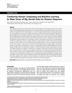
This buffer is then used as input by the kernels devoted to the S2K procedure. Because the number of passphrases in the input dictionary can be arbitrarily large, we split them into chunks to fill the passphrase buffer. The application continues to read the input dictionary in chunks until either a passphrase is found or the dictionary is depleted. We measured the bandwidth of the GPU by loading the 41
buffer in chunks of incrementing sizes (see Figure 2.16). From the results we can see that to achieve 99% of throughput we need, at least, a chunk of 4MB in size. For what concerns the secring, the relevant data are copied in constant memory. The constant space is a special, read-only, memory that is directly referenceable by the kernel. Copied data include the salt and byte count for the iterated and salted mode of SHA1, the Initialization Vector (IV) used by CAST5 and finally the secret key ciphertext, the target of our attack.
2.6.2
Computing Kernels
The passphrases in the input buffer are processed by the S2K kernel to produce the corresponding CAST5 keys. These keys are in turn read by the CAST5 kernel that, by using the constant secring data, carries out the decryption of secret key ciphertext and the fast test on the resulting plaintext. We initially developed two independent and complete kernels for the S2K and CAST5 steps. The arguments of each kernel are: • SHA1 kernel: passphrase buffer, passphrase length, salt, byte count and output buffer for digests (CAST5 keys). • CAST5 kernel: key buffer, Initialization Vector, secret key ciphertext and output buffer for the fast test outcomes. Each thread processes the passphrase corresponding to its global ID: ID = blockIdx ∗ blockDim + threadIdx where blockIdx is the ID of the thread block, blockDim is the kernel block size and threadIdx is the ID of the thread within the block. Each thread processes only one item (passphrase or key) corresponding to its ID. If the thread ID is greater than the total number of items, then it terminates. This is a simple and effective choice, since it avoids complex logic and any kind of synchronization requirement. 42
Figure 2.17. String-to-key kernel scheme.
Figure 2.18. Iterated and salted passphrase.
Through a process of fine tuning and continuous testing, we subsequently merged the SHA1 and CAST5 kernels into a single and faster kernel. String-to-key Kernel The string-to-key (S2K) mechanism requires to generate the SHA1 digest of the passphrases in iterated and salted mode. The procedure requires to apply SHA1 to a sequence of bytes by repeating the concatenation of the salt to the passphrase (see Figures 2.17 and 2.18). The salt and the length of the sequence are both specified inside the secring. Since that sequence is quite large (216 bytes), allocating the whole buffer for it (for every thread) could be overwhelming. The solution adopted is to store only enough space to handle the data required by a round of the SHA1 algorithm (64 bytes). CAST5 Kernel The CAST5 procedure is divided in two phases. In the first step the state of the cipher is initialized, by using a set of byte-transformation tables. Before launching the kernel we load these tables inside the constant memory of the device. Although the constant memory is limited, the tables are small enough to fit inside 43
it. Each thread loads from device memory the key (produced by the S2K kernel) corresponding to its own global ID. In the second step, an amount of encrypted data equal to the CAST5 block size (64 bit), is read from constant memory for the decryption. SHA1 digests are used as keys for the CAST5 block cipher. If the length of the ciphertext is greater than the cipher block size, multiple iterations are required to complete the decryption. Once the first three bytes (i.e. the first part of the MPI number) are decrypted, we perform the fast test. If the test is successful, we store in global memory the thread ID value inside the corresponding result element, otherwise we store a negative value (-1). S2K+CAST5 Kernel While the registers and local memory are flushed away at each kernel invocation, the global memory of the device is not. Instead of launching the SHA1 kernel, storing its results in memory, launching the CAST5 kernel, fetching the results from SHA1 and computing the final result, we merged the two kernels into a single one, avoiding in such a way, 2 × N accesses to global memory, where N is the number of passphrases processed by a block of GPU threads. The final kernel performs the following steps: 1. Loads the secring data from the constant memory. 2. Loads the passphrase from the global memory. 3. Computes the S2K. 4. Applies the CAST5 cipher to the ciphertext. 5. Carries out the fast test. 6. Saves in global memory the result of the test.
44
2.6.3
Output
After the kernel completes, the whole result buffer is copied back into host memory so that the CPU can scan it. The result data structure is simply an array with one element for each analyzed passphrase. The element is an integer equal to either -1, if the passphrase did not pass our fast test, or a non negative number corresponding to the index of the passphrase in the input array. When a valid entry is found, the CPU thread retrieves the corresponding passphrase and completes the last two tests of the standard procedure. Only the correct passphrase can pass the last test so, in case of success, it is communicated to the user and the attack ends. In the distributed version of the attack, the final result would be notified to the root node [2]. We investigated the chance of using a reduction mechanism, the classic parallel technique of stream compaction via prefix-sum [27] to select from the result structure only the positive values, compact them and download only the relevant part of it instead of the whole buffer. Due to the small footprint of data transmission, there are few benefits in using this technique so we dropped it in favor of a simpler code.
2.6.4
Code Optimizations
This section describes the various techniques we employed to improve the execution speed of our attack when running on GPU. Due to the novelty of the architecture and programming paradigm, we tried different approaches before reaching a satisfactory speed. Our main reference in this study has been the excellent CUDA Best Practices documentation provided by NVIDIA [29]. We started by measuring the time required to process a dictionary of one million passphrases of different length. The test was conducted on a Intel Xeon E5462 CPU (2.8 Ghz, 6 MB of cache) running a single thread by using randomly generated passphrases between five and sixteen characters long as input, with no
45
additional rules applied to them. The resulting reference time is 505 seconds. Of all the three steps performed on the GPU, the string-to-key step is the main focus of our optimizations. String-to-Key Optimization To gain some more insight into the mechanism of the byte-shuffling operation performed by the S2K procedure and get some ideas on possible optimizations, we analyzed the machine code produced by the compiler for the GPU. A large number of registers is spilled in the iterated and salted phase. This happens because of the continuous use of the local buffer, to store and fetch the state of the SHA1 algorithm and to populate and read the salted buffer. The contents of the buffer are loaded into the registers, processed and then swapped back to local memory, resulting in a large number of data movement operations. The main kernel optimizations implemented are the loop unwinding of the SHA1 round logic and the preprocessing of the data access pattern for the buffer. Loop unwinding (or loop unrolling) is a classic optimization technique [30]. The goal of this technique is to increase a program speed by reducing or eliminating the instructions controlling the loop, such as pointers arithmetic and end of loop tests, that occur on each iteration. Alternatively loops can be re-written as a repeated sequence of similar independent statements, thus eliminating this overhead and improving the data parallelism among register operations. In our case we have a sequence of loops for each stage of the SHA1 algorithm. With the aid of a script program2 , we generate a CUDA-language source code of the unrolled version. The resulting kernel is 20 times faster than the CPU code (see Table 2.1). To process our test case of one million passphrases, it takes only 26 seconds, compared to the former time of 505 seconds. 2
written in the Python language, www.python.org
46
Version
Time (Seconds) Speed Up
CPU single thread
505
1×
GPU v.1 loop unrolling
28
20×
Table 2.1. GPU Version 1: Loop unroll.
Actually, the speedup is not only a consequence of the additional free registers but also of the intrinsic data parallelism that we introduced by unrolling and untangling the operations of the loop. Many of the SHA1 inner operations are independent from each other and this code change allows the threads to fill the hardware pipeline consistently. The next optimization regards the access pattern to the buffer used to salt and iterate the passphrase. Our target hash is the result of SHA1 on the entire buffer created by repeating the concatenation of the salt to the passphrase. As already mentioned, we store only the intermediate block required by a single round (512 bit) and fill it iteratively with the salt and the passphrase. However, the observation that the bytes used to feed the S2K procedure are always the same (i.e. the salt and the passphrase), suggested to create a reduced buffer containing only the salt and the passphrase. To simplify the operations we extended this buffer with four more bytes of the first part of the salt in order to simplify the lookup operations (more details below). The resulting, reduced buffer is arranged in such a way that is easy to extract the required sixteen values for one round of SHA1. To fully comprehend this optimization, it is necessary to describe how the SHA1 round works. To start a SHA1 round, we need a buffer of exactly 512 bit (64 bytes). Sixteen 32 bit values are extracted and processed from this buffer (16 × 4 bytes). For each of these input values, we compute the position in the circular buffer of each of their four bytes.
47
Code 1 C++ code of the improved S2K logic. unsigned int shift = SALT_LEN + passhphrase_len;
for (int it = 0; it < 1024; it++) { int offset = (it * 64);
// compute input value 1/16 start =
0 * 4 + offset;
start = start - shift * (start / shift); x00 = (buff + start)[0]